Erik's Duet PCB
Posted by Radian
|
Erik's Duet PCB March 21, 2014 06:43AM |
Registered: 10 years ago Posts: 300 |
Hi Erik, I wanted to offer some help with your soldering woes so I started a fresh topic. Hope you don't mind.
What I was going to add to the advice you were getting here [forums.reprap.org] is that the solder resist coating (blue lacquer in this case) is your biggest allie... even with that big soldering iron working against you.
Obviously it might be a good idea to practice any of the advice you get on a scrap circuit board with Surface Mounted parts before hand. I don't know about you but I keep a pile of old PC, TV and other assorted circuit board for emergency component scavenging!
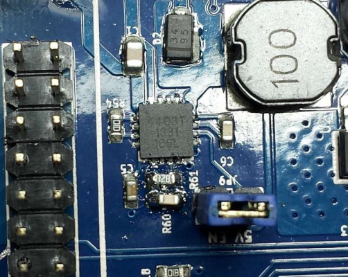
Anyway, if you want to try it, the biggest help you have is that the solder resist coating repels molten solder quite efficiently so, with a little drop of liquid "no-clean" flux, you don't have to be utterly precise with your iron tip. What I mean by this is that you could remove both resistors in one go by adding a drop of flux, then add some solder to both ends of the resistors - bridging between them and working quickly back and forth between both ends. It just doesn't matter that you're joining things together in a big solder blob at this stage. The aim is just to get both resistors off in one go. What would happen is that after a couple of seconds they would start to slide around - at which point you would push them with the iron tip into the clear area (overprinted with R60). Thanks to the blue solder resist, and a drop of flux, the pads should be left neatly tinned and still well-defined. Just as a precaution I'd press some paper masking tape across the top and edge of the IC to protect the pins at the edge before you start.
Once the resistors are off you can then clean the excess solder off them, working on some kitchen paper towel using a drop more flux. Tweezers now become essential to hold each resistor while you dab them with the iron and smudge the solder off. Check them with an Ohm meter if you're not going to replace them with new ones. They're probably OK for this application.
On re-soldering them, the "trick" is to be very sparing with the solder and use "no clean" flux again. If you don't have any fine solder, you can use a razor blade to shave off a fine point to whatever you have. Only a pin head's worth is needed (and a fairly steady hand). If you find it hard working with tweezers in one hand and an iron in the other, you could mix a tiny amount of epoxy resin and pre-attach the resistors using a dab of resin applied in between the pads with a tooth pick. If you do get into trouble with excess solder, apply a drop more flux and wipe away with the clean iron tip.
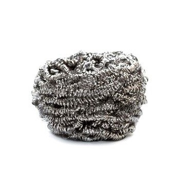
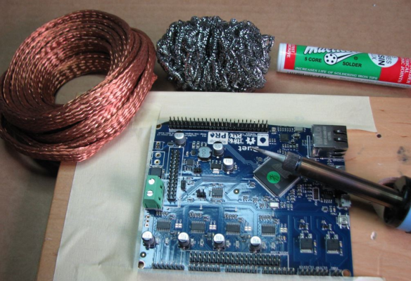
That brings me to my last tip - get a stainless steel wool kitchen pan scourer and wipe the iron tip on that to clean it each time before you use it. They make wonderful tip cleaners (unlike wet sponges, they don't draw heat away and make so much mess). With a pristine tip, and flux on the solder you need to reduce, some solder will flow onto the tip acting like a solder sucker.
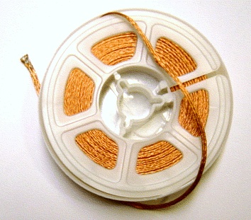
You can also buy de-solder braid (or make some using the braid stripped from thin coax cable soaked in flux e.g. screened audio cable).
RS Components Reprap Ormerod No. 481
|
Re: Erik's Duet PCB March 21, 2014 07:44AM |
Registered: 10 years ago Posts: 256 |
A good tip for desoldering SMD components without expensive gear... Get some copper wire and bend it into a shape to sit on the solder joints ( A "Z" with a bend in the top works well for resistors). Tin the copper wire where it meets the joints. and in the middle at the top where you will apply the (big) iron Then sit the coper wire in place and heat the middle of the wire. Use a scalpel and when everything is shiny hot, flip the part off the pcb... Done !
regards
Andy
Ormerod #318
www.zoomworks.org - Free and Open Source Stuff
regards
Andy
Ormerod #318
www.zoomworks.org - Free and Open Source Stuff

|
Re: Erik's Duet PCB March 21, 2014 01:04PM |
Registered: 10 years ago Posts: 101 |
If you search youtube for "desoldering smd components" there's a lot of good information - e.g. [www.youtube.com]
A very fine-tipped tweezer is essential for re-soldering the small components again. Search ebay for "fine tweezer" and buy the one with the finest tips. You don't need to pay more than a few $$.
Often I just apply excess amounts of solder for both removing and re-soldering small components. Then I remove the excess solder using desoldering braid - one pad at a time.
At my job we use "Chemtronics Desoldering Braid Soder-Wick Rosin". It works incredibly well. I never use no-clean, as it is not as effective as the more aggressive types. For PCBs used i normal indoor (dry) environments I have not seen any problems with flux-residue. Otherwice it should be possible to remove flux residue using alcohol or similar and a small brush with fine but a bit stiff hairs.
This was the very short version of my 7 years of daily soldering SMDs :-)
If you need a microscope, the "andonstar" works very well for the price - search ebay. Here's a review:[www.youtube.com].
Best regards
Carsten
|
Re: Erik's Duet PCB March 21, 2014 02:19PM |
Registered: 10 years ago Posts: 2,472 |
I have to work on fine SMD boards quite often.
To get parts off the board, do as Radian suggests - feed a big blob of solder over all the pads and push the component to a clear area of board with the tip of the iron. Once clear of the pads it will then usually stick to the tip of the soldering iron and can be lifted off along with the blob of solder, and can be flicked off onto the worktop. Then use solderwick to mop up all the excess solder from the board, and if needed for re-use, the removed component as well.
To solder small parts back on the board, first ensure the pads on the PCB are flat and well tinned, and also the pads on the components. Then place the (cold) component into position on the pads using tweezers, or slide it into place with a small screwdriver. Tin the soldering iron tip and then wipe it off so it is bright silver but has no solder blobs on it. I then find it easiest to hold the component in place by pressing down on its middle with a small (jeweller's) screwdriver - and with the component thus prevented from moving, touch the tip of the iron to each junction between pad and board and hold for about 5 seconds on each pad. Do not add any additional solder - just let the tinning on the board and component pads flow together. Painting a bit of liquid flux on the board pads first with an artist's brush will help, but is not essential.
The trick is to avoid heating the PCB pads for too long, else they will lift and repair can then become impossible. That's why a big blob of molten solder that covers everything is good - it gets the component off quickly. Just try to avoid getting solder on any fine-pitch IC pads that are nearby - though if you do, then again solderwick will clean it up.
Dave
(#106)
|
Re: Erik's Duet PCB March 22, 2014 12:14PM |
Registered: 10 years ago Posts: 1,230 |
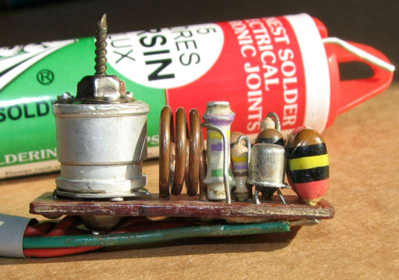
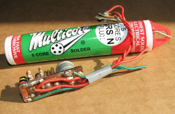
Thank's a lot for all the great advice guys! - it's been a long time since I done any electronics and never have worked with such tiny parts, here's a couple of picture of my latest build from about 45 years ago, a FM band transmitter, now that was called tiny back then...
this is where I am, have removed and measured R60 and R61
was vertical left, marked 126E: 3K9
was vertical right, marked 35A: 750 (or should that be 680/820?)
I have some 1/8 watts resistors to chose from if the SMD's should fail
Without knowing the layout or what goes where, from dc42 former posted picture and the marking on the SMD's I would guess that the 3K9 should go horizontal top and the 750 should go horizontal bottom - is that right?
..and I should ad a jumper on JP9?
Erik
|
Re: Erik's Duet PCB March 22, 2014 02:01PM |
Registered: 10 years ago Posts: 314 |
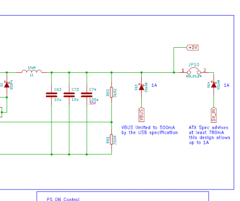
Here is a link to the schematic as a pdf.
[github.com]
and here is the R60/61 bit....
R60 is the 3k92 and
R61 is the 750R, so think this is opposite to what you statedr re top and bottom values?
Yes jumper is required.
Edited 1 time(s). Last edit at 03/22/2014 02:03PM by Treth.
Ormerod #007 (shaken but not stirred!)
[github.com]
and here is the R60/61 bit....
R60 is the 3k92 and
R61 is the 750R, so think this is opposite to what you statedr re top and bottom values?
Yes jumper is required.
Edited 1 time(s). Last edit at 03/22/2014 02:03PM by Treth.
Ormerod #007 (shaken but not stirred!)
|
Re: Erik's Duet PCB March 22, 2014 02:41PM |
Registered: 10 years ago Posts: 1,230 |
|
Re: Erik's Duet PCB March 22, 2014 02:55PM |
Registered: 10 years ago Posts: 14,672 |
To clear up any confusion, I used slightly different value resistors because I didn't want to re-use the resistors I de-soldered and I didn't have the original values. I used 820R for R61 and 4.3K for R60, hence the marking 820 on R61 in the photo. The important thing is the ratio between these resistors, which should be 5.25:1.
Large delta printer [miscsolutions.wordpress.com], E3D tool changer, Robotdigg SCARA printer, Crane Quad and Ormerod
Disclosure: I design Duet electronics and work on RepRapFirmware, [duet3d.com].
Large delta printer [miscsolutions.wordpress.com], E3D tool changer, Robotdigg SCARA printer, Crane Quad and Ormerod
Disclosure: I design Duet electronics and work on RepRapFirmware, [duet3d.com].
|
Re: Erik's Duet PCB March 22, 2014 04:57PM |
Registered: 10 years ago Posts: 300 |
I like your FM "Bug" Erik ;-)
I've had a thing about sticking to no-clean flux ever since ruining several days work on a large illuminated switch matrix on which I'd used a more agressive flux that hid under the switches and then secretly ate the copper tracks.
RS Components Reprap Ormerod No. 481
I've had a thing about sticking to no-clean flux ever since ruining several days work on a large illuminated switch matrix on which I'd used a more agressive flux that hid under the switches and then secretly ate the copper tracks.
RS Components Reprap Ormerod No. 481
|
Anonymous User
Re: Erik's Duet PCB May 02, 2014 02:34PM |
|
Re: Erik's Duet PCB May 03, 2014 02:59PM |
Registered: 10 years ago Posts: 1,230 |
Quote
Conseils
Awesome FM transmitter.
Thank You! - was made with young eyes
BTW I never finish the tread properly, yes I managed to turn and re-solder the resistors and have been stand alone omerod printing ever since - here's a just before picture, I won't show a after close-up, it's not that pretty, but hey it works - BTW, I have left over solderwick if anyone should be in need
A big thank you to Radian for starting this thread, I had not been able to pull myself together to do this without your advice and encouragement!
Yes we have no "no clean" flux, but I did do without :-)
The stainless steel wool is brilliant for cleaning the iron tip, never did think of that, its now standard equipment here at work
kwikius - used your copper heat bridge trick, worked like a charm!
colsenfoto - fine-tipped tweezer added to the toolbox, can't do without now, thank you
Thank You all!
Erik
|
Re: Erik's Duet PCB May 03, 2014 05:05PM |
Registered: 12 years ago Posts: 1,611 |
If you've got a board with the resistors the wrong way around, we'll exchange it under warranty! Just email me on support at reprappro dot com with a description of the problem, your full name and address, RS order number and machine number from the certificate that came with the kit. I'll send you the address to return your Duet to. If you're nice, we'll even post it out, so you can fit it, before returning the old one!
Ian
RepRapPro tech support
Ian
RepRapPro tech support
|
Re: Erik's Duet PCB January 04, 2015 12:47PM |
Registered: 10 years ago Posts: 1,230 |
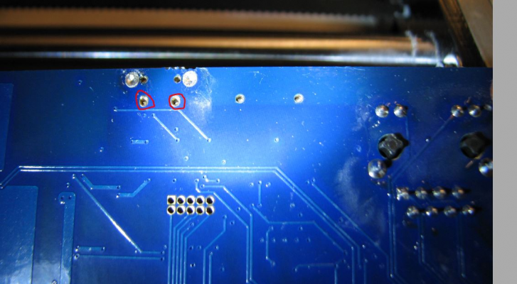
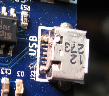
Duet PCB - do this look right or should there be solder? (red circles) - I think I can see short pins down the two holes
Erik
Erik
|
Re: Erik's Duet PCB January 04, 2015 07:05PM |
Registered: 10 years ago Posts: 14,672 |
Yes, there should be solder in those holes, at least on the top side where the USB connector pins fit into them. One of my 3 Duets is also missing solder in those holes, another has solder there, and on the third I think I soldered those pins myself.
Large delta printer [miscsolutions.wordpress.com], E3D tool changer, Robotdigg SCARA printer, Crane Quad and Ormerod
Disclosure: I design Duet electronics and work on RepRapFirmware, [duet3d.com].
Large delta printer [miscsolutions.wordpress.com], E3D tool changer, Robotdigg SCARA printer, Crane Quad and Ormerod
Disclosure: I design Duet electronics and work on RepRapFirmware, [duet3d.com].
|
Re: Erik's Duet PCB January 05, 2015 03:04AM |
Registered: 10 years ago Posts: 1,230 |
Quote
dc42
Yes, there should be solder in those holes...
Thanks, will try to get a small piece of solder down there and ad heat to the track, I guess the right way would be to heat the pins and then ad the solder but thats not possible
BTW, talk about loose connections, did a repair of my lenovo x220 switch mode power adapter, sliced the abs casing, removed the aluminium shielding and lifted it with my bare hand, bad idea, there's quite a massive capacitor in there and it was still holding 300V after my handshake
Erik
|
Re: Erik's Duet PCB January 05, 2015 03:24AM |
Registered: 10 years ago Posts: 14,672 |
Erik, you can heat and solder those USB shield pins from the top of the board.
You've learned the hard way that switching power supplies must always be dismantled with caution, because of the charge that may be held in the reservoir capacitor after the power is removed.
Large delta printer [miscsolutions.wordpress.com], E3D tool changer, Robotdigg SCARA printer, Crane Quad and Ormerod
Disclosure: I design Duet electronics and work on RepRapFirmware, [duet3d.com].
|
Re: Erik's Duet PCB January 05, 2015 12:01PM |
Registered: 10 years ago Posts: 1,230 |
Quote
dc42
Erik, you can heat and solder those USB shield pins from the top of the board.
Did, solder came right thought to the top side, thank you!
Erik
Sorry, only registered users may post in this forum.
