X axis problems
Posted by Dodger
|
X axis problems March 12, 2015 08:11AM |
Registered: 9 years ago Posts: 13 |
In a previous message I mentioned that I had reconfigured my Ormerod 2 to a box type structure. However I started to run into printing problems and decided to rrevert back to the original Ormerod configuration. Apart from one or two Items that cracked it went back relatively easily. On test it did everything it should except print!! Eventually I trcked it down to the fact that I had replaced the glass plate upside down with the Kapton tape on the bottom.!! It is now printing but I have a problem with what appears to be a step input on each layer of the X axis and I hape a perfectly formed face that is leaning by about 15 degrees. This was on a piece which was about 12 mm high,. I have not done anything with the axis compensation as I cannot believe that it will have such a large effect. I am using thr RepRap Pro firmware. Any Ideas?
Dodger
Dodger
|
Re: X axis problems March 12, 2015 08:32AM |
Registered: 12 years ago Posts: 1,611 |
Hi Dodger
I'd expect it is a mechanical issue, unless you have some strange settings for bed and orthogonal axis compensation. Try running a print with them turned off . If you get the same again, most likely the X motor pulley is loose.
For other causes, see this section of the troubleshooting, and the two sections following it: [reprappro.com]
Ian
RepRapPro tech support
|
Re: X axis problems March 12, 2015 11:56AM |
Registered: 9 years ago Posts: 13 |
Thanks Ian, Ihave tried several other prints ans exactly the same happens and the face that should be vertical remains at an angle of about 15 degrees. If ity was a machanical problem then I would not expect this consistency. You suggest I try with the bed and axes compensation off - presumably the bed compensation just dont run G32 how do I disable the orthoganal axes compensation?
|
Re: X axis problems March 12, 2015 12:19PM |
Registered: 12 years ago Posts: 1,611 |
|
Re: X axis problems March 12, 2015 02:02PM |
Registered: 9 years ago Posts: 13 |
|
Re: X axis problems March 12, 2015 02:41PM |
Registered: 9 years ago Posts: 177 |
Quote
Dodger
Thanks again - that seems to have done it. The question now is where did the strange number come from? Would I be advised to delete and reinstall the firmwhere?
Dodger
The only place that should be is in your config.g file, under the M556 command. Your X, Y, and Z values probably aren't 0.
Here's how that line appears in the RRP github config:
Quote
M556 S78 X0 Y0 Z0 ; Put your axis compensation here
You'll probably want to print the axis compensation part and set these values to what they ought to be though... it's doubtful that your setup is perfectly square.
|
Re: X axis problems March 13, 2015 01:41PM |
Registered: 9 years ago Posts: 13 |
Hi ,
After several disastrous attempts at printing various objects all of which sloping faces to differeny extentas, I decided that I had to pull the x axis apart. Lo amd behold the belt drive pulley did not have the grub screw located on the flat on the stepper motor It looks as if Ian is right again. The fact that I got a satisfactory print with the compensations turned off must have been cioincidence. I have not tried printing but am fairly sure this was the problem. Thanks to all.
Dodger
|
Re: X axis problems March 19, 2015 08:04AM |
Registered: 9 years ago Posts: 13 |
Hi,
I am glad to say that fastening the drive pulley onto the X motor properly has solved my x drive problem - thanks Ian
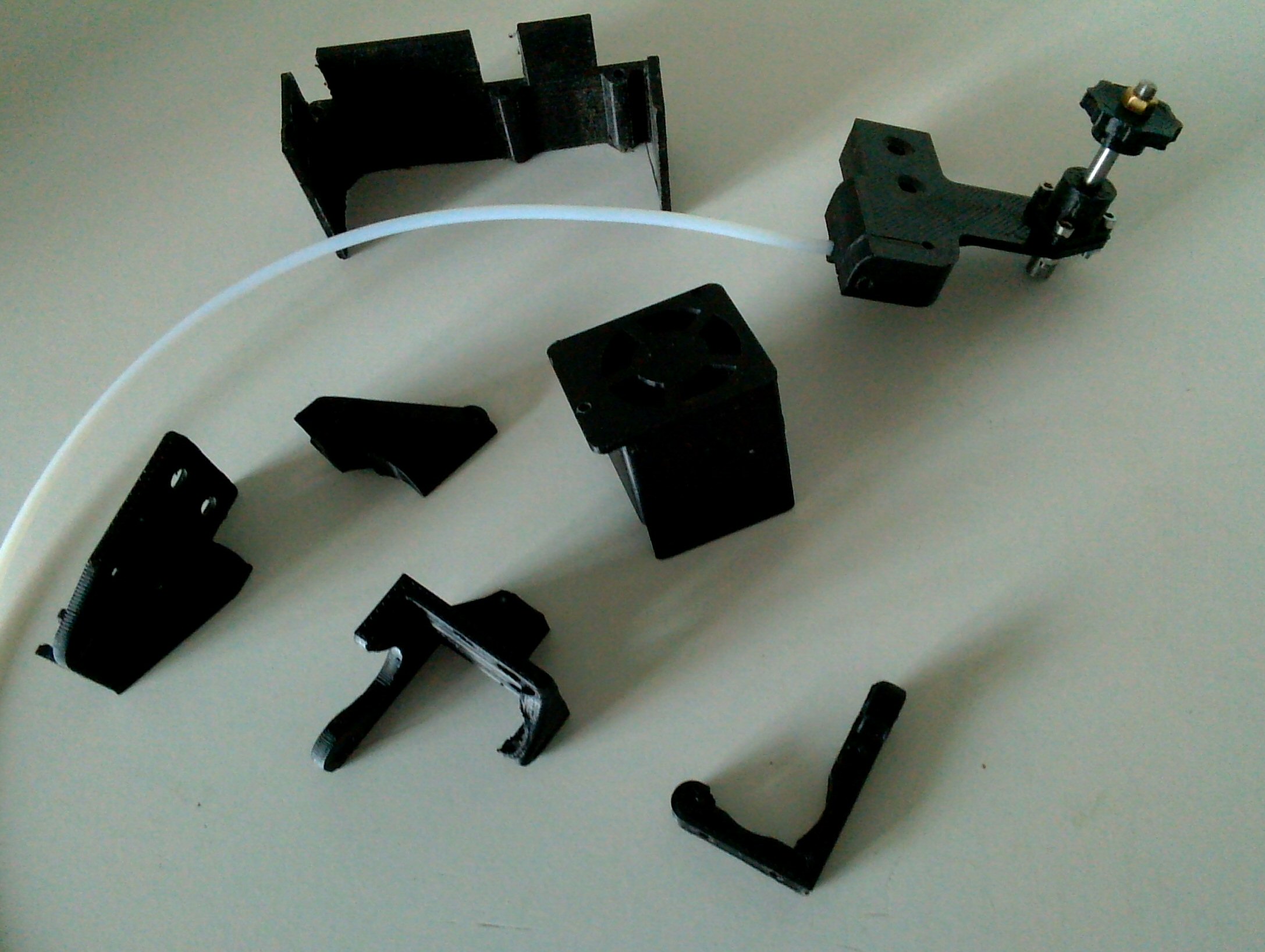
The attached photo shows some of the new parts for my Ormerod The Z axis nut retainer had a crack in the top left corner so I took the oportunity to put a longer brass nut on it. The Z axis top has been altered to carry an extension to the Z axis screw with a wheel on top so the Z screw can be turned manually and also a hole to carry a piece of 4mm ptfe tube to guide the filamen
Does anyone know of a method to revert .stl files back to a CAD file?
Dodger
I am glad to say that fastening the drive pulley onto the X motor properly has solved my x drive problem - thanks Ian
The attached photo shows some of the new parts for my Ormerod The Z axis nut retainer had a crack in the top left corner so I took the oportunity to put a longer brass nut on it. The Z axis top has been altered to carry an extension to the Z axis screw with a wheel on top so the Z screw can be turned manually and also a hole to carry a piece of 4mm ptfe tube to guide the filamen
Does anyone know of a method to revert .stl files back to a CAD file?
Dodger
|
Re: X axis problems March 19, 2015 08:35AM |
Registered: 10 years ago Posts: 2,472 |
Quote
Dodger
Does anyone know of a method to revert .stl files back to a CAD file?
Dodger
Many CAD programs allow you to import an STL file (you can do it in OpenScad). However an STL file describes the whole item, it contains none of the original information regarding the different elements that make up the part (cylinders, cubes, holes etc). Importing an STL file is akin to scanning in a paper document that you have printed out from (say) "Word" and importing into "Word" as a JPEG image - you will lose all the formatting and settings of the original Word document and making even a simple change to the text will be difficult.
By importing an STL you will be able to modify the part by cutting sections or adding sections, re-sizing & mirroring etc, but you will not be able to do things such as changing the size of an existing hole or moving the position of a rib etc. There may be the equivalent of an OCR convertor for STL files that can recognise and convert basic shapes, but I have not come across such an application (and if it exists it would probably need as much tweaking as the average OCR derived document).
If I wish to modify an existing STL, I usually import the STL into OpenScad but use it only as a visual template to re-create the part from scratch - unless I only need to do a trivial change such as adding a hole or cutting the part into sections etc.
Dave
Sorry, only registered users may post in this forum.