Inductive Z-height sensing
Posted by Radian
|
Inductive Z-height sensing May 07, 2015 12:04PM |
Registered: 10 years ago Posts: 300 |
So here I am again with yet another method for sensing Z height. To be honest, dc42 has probably nailed it with his dual IR hot-end board v2 but out of interest I'm developing an inductive sensor to see if it can out-perform my current probe which is my own capacitive design: [forums.reprap.org]
As always, the motive is to replace the simple RepRap sensor which has improved by incorporating dc42's modulated detection but still requires reflective targets and is sensitive to ambient IR (unlike David's v2 design).
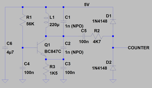
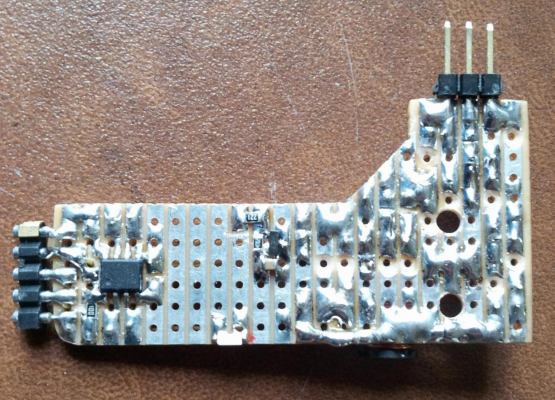
The new circuit operates by exciting an LC tank at resonance using an off-the-shelf inductor driven by a single-transistor Colpitts oscillator. With this arrangement the alternating magnetic field induces an opposing field due to eddy currents in the aluminum heat spreader under the glass which effectively reduces the inductance value - so increasing the frequency at resonance. So yes this scheme does require a conductive plane under the glass (unlike David's). However, I'm quite satisfied with this condition. To measure the frequency I use the same 8-pin PIC12F1822 used in the capacitive sensing. The internal functions are a perfect match for the design: three timers, one used to gate a second timer that counts cycles form the LC oscillator and a third timer that generates scaled PWM emulating the Z-probe value fed into to the Duet A/D. Also, an on-board temperature sensing module is used to compensate for ambient temperature effects on the system as a whole.
The handy thing about having an aluminum substrate under the probe is that it's a good electrical conductor and as a consequence produces a strongly opposing field that alters the inductance of the field coil hence shifting it's resonant frequency without affecting its amplitude - ideal for counting. This is in contrast to sensing ferrous materials which give a smaller shift in frequency but bigger change in amplitude. This is why (I think) industrial inductive proximity sensors look at the current going into the coil (which is a bit more involved).
The circuit is pretty basic and should be easy for anyone to reproduce. The COUNTER output is approx. 200KHZ and swings rail to rail. I feed it into a GPIO pin on a PIC chip but it could simply trigger a monostable to generate a direct analog voltage (PWM/CR filter). Without a micro though there would be no temperature compensation or calibration but it would be OK if Z-probing was always done at room temperature.
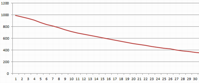
By counting the number of cycles for a fixed duartion, the variation in frequency I see over Z height from 0 to 3mm translate to PWM values of around 1000 (1023 =5Vout) to 350 (1.7Vout) as plotted below:
The vertical scale is the 10-bit value I feed into the PWM output stage and the horizontal is the corresponding separation between the nozzle and the bed in 0.1mm steps. I was surprised at how close to linear the response is.
RS Components Reprap Ormerod No. 481
|
Re: Inductive Z-height sensing May 07, 2015 04:21PM |
Registered: 10 years ago Posts: 780 |
Looks good, I might give it a try,
Is it possible to add lights, as in dc42's sensor?
Are the results consistent regardless of bed temperature, if not what is the recommended way t set up?
What are the pros and cons?
What changes to config are required?
Thank for your efforts
Edited 1 time(s). Last edit at 05/07/2015 04:23PM by appjaws1.
appjaws - Core XYUV Duet Ethernet Duex5
firmware 3.1.1 Web Interface 3.1.1
Ormerod 1-converted to laser engraver, Duet wifi
OpenSCAD version 2020.07
slic3r-1.3.0, Simplify3D 4.1.2, Cura-4.4.1
|
Re: Inductive Z-height sensing May 07, 2015 05:30PM |
Registered: 10 years ago Posts: 300 |
Hi there appjaws1. It certainly is possible to extend the functionality in all those ways - lights are easy, however I think temperature compensation is really only practical with a small micro-controller. However, this isn't needed if Z homing and bed compensation are always done at room temperature as drift only becomes measurable above 30C or so.
Already I can see that the inductive sensor is far less sensitive to temperature variations than the capacitive version I made. I think the changing humidity of the air was the biggest problem with that method: big temperature fluctuations result in big changes in RH and hence capacitance of the air-gap being measured.
While the use of NPO capacitors in the LC tank oscillator should provide a 0% temperature coefficient all the other components have a finite temperature-dependent shift in value. Of these I think the inductor and the PIC internal oscillator doing the timing have the biggest influence.To compensate for all contributions I've obtained a calibration factor by logging the values from the timer/counter and on-board temperature sensor over the full range of operating temperatures with the probe at a fixed distance. From this data I scale the measurement and get a maximum of 5 counts deviation in the PWM translating into something like 0.025mm error over the range 20C to 70C.
Of course tor this compensation scheme to work well all the components have to be at the same temperature which means being as small as possible (ideally SM) and close together. Potting it all in something like a polyester compound may help but my prototype is far form these ideals yet seems quite workable nonetheless.
Because the full design with the micro-controller produces an analog output voltage it uses the same standard config as used for the stock IR Z-probe.
RS Components Reprap Ormerod No. 481
|
Re: Inductive Z-height sensing May 08, 2015 07:49AM |
Registered: 10 years ago Posts: 2,472 |
|
Re: Inductive Z-height sensing May 08, 2015 01:24PM |
Registered: 10 years ago Posts: 300 |
Quote
dmould
Interesting. Do you get consistent values at the edges, corners and center of the bed?
Dave
Hi Dave, yes it's very consistent so long as the inductor is kept around 20mm from an edge.
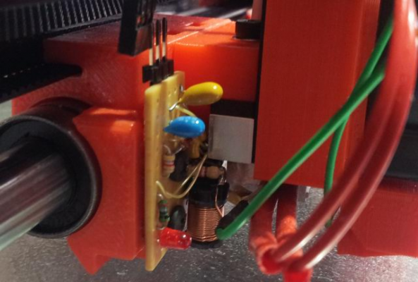
Just for giggles, the above photos show the test circuit I've lashed together. I've hacked in a fan control and white LED (SM edge lit device) that sits right next to the nozzle.
RS Components Reprap Ormerod No. 481
|
Re: Inductive Z-height sensing May 09, 2015 11:11AM |
Registered: 9 years ago Posts: 177 |
|
Re: Inductive Z-height sensing May 09, 2015 11:25AM |
Registered: 9 years ago Posts: 1,699 |
|
Re: Inductive Z-height sensing May 09, 2015 12:06PM |
Registered: 10 years ago Posts: 300 |
Hi Treito, the inductor L1 is nothing special at all - it's an open bobbin type (fully shielded would not work at all) but apart from that, almost any similar sized part would do. I had this one in my parts box as well as a 68uH and that worked just as well - although of course the resonant frequency went up accord to:
[en.wikipedia.org]
The capacitance value of C1 (which must also be the value used for C2) is similarly flexible, I chose 1nF because I had some zero. temperature coef. caps in that value. I wouldn't go below 1nF as we want stray capacitance to have little effect on the stability. I think ideally I'd raise the value to 10nF and drop the inductance to compensate.
It's very easy to count the oscillator cycles with an Arduino or PIC micro, so long as the chosen frequency is high enough to give a significant count difference over the detection range and not so high that it overflows the counter! The PIC I'm using has a hardware gated timer/counter which is great for this as it removes interrupt or software polling latency from the measurement process
Edit: This is the sort of inductor I used [uk.rs-online.com].
Edited 1 time(s). Last edit at 05/09/2015 12:17PM by Radian.
RS Components Reprap Ormerod No. 481
|
Re: Inductive Z-height sensing May 09, 2015 03:42PM |
Registered: 9 years ago Posts: 1,699 |
Many thanks for this detailed reply. I was asking because I wondered if such kind of inductive coils may work, because that is not their main purpose. I thought of some kind of coils with an open part of metal. I do not know how to explain what I am thinking off - such kind of coils which are used for example in door bells.
|
Re: Inductive Z-height sensing May 09, 2015 06:30PM |
Registered: 10 years ago Posts: 300 |
I think you may be referring to a solenoid. The properties are pretty much the same as an inductor in that an electric current flowing in any conductor produces a magnetic field. The aim of this circuit is to create a rapidly alternating magnetic field which in turn produces an opposing field in the aluminum due to the induced AC current. A plain coil of wire would be the most the efficient (air-cored) if we were trying to transfer power but this is not the case. Only the ratio of the two fields is of interest when determining proximity. I think dc42 was looking to wind an air-cored inductor but I see no great advantage given that a decently measurable effect can be obtained with a standard ferrite core.
RS Components Reprap Ormerod No. 481
RS Components Reprap Ormerod No. 481
|
Re: Inductive Z-height sensing May 09, 2015 06:39PM |
Registered: 10 years ago Posts: 14,672 |
When I was thinking of trying an inductive sensor, I found and purchased some ferrite cores and bobbins made for this purpose. The core is like the usual half cores you find that are used in pairs when making transformers, except that these cores are the full length of the bobbin. So there is one open end, where the magnetic flux is concentrated, giving high sensitivity to metal objects at that end. But in the end, I decided to concentrate on methods that sense the top surface of the glass.
There are some posts on other RepRap forums about using off-the-shelf inductive sensors for this purpose too.
Large delta printer [miscsolutions.wordpress.com], E3D tool changer, Robotdigg SCARA printer, Crane Quad and Ormerod
Disclosure: I design Duet electronics and work on RepRapFirmware, [duet3d.com].
|
Re: Inductive Z-height sensing May 09, 2015 06:55PM |
Registered: 10 years ago Posts: 300 |
I guess I ought to take a look but I find it hard enough finding time to keep up with posts in this forum alone. Really I'm just playing around with the analog circuit and magnetics for the fun of it. Makes a nice change from coding all day. I read how you wanted to concentrate on IR surface sensing and I agree that's probably the best all-round solution - especially seeing as it only requires a few inexpensive components.Quote
dc42
There are some posts on other RepRap forums about using off-the-shelf inductive sensors for this purpose too.
RS Components Reprap Ormerod No. 481
|
Re: Inductive Z-height sensing May 13, 2015 05:43PM |
Registered: 10 years ago Posts: 300 |
I'm having a hard time getting Z homing to reach a consistent height using an analogue voltage. I know the voltage I generate proportional to Z height is consistent and I know the analogue ground and general hash in the Duet is causing the reading to jitter as discussed before.
So is there anything wrong with me simply thresholding my detection to produce a digital high or low as though Z was a micro-switch homed axis? More specifically would bed leveling still work - and would X homing still take Z as the trigger?
I'm not understanding the description for M558: [reprap.org]
Why not the Z endstop pins?
RS Components Reprap Ormerod No. 481
So is there anything wrong with me simply thresholding my detection to produce a digital high or low as though Z was a micro-switch homed axis? More specifically would bed leveling still work - and would X homing still take Z as the trigger?
I'm not understanding the description for M558: [reprap.org]
Quote
P4 selects a switch (on the Duet, this must be connected to the E0 endstop pins).
Why not the Z endstop pins?
RS Components Reprap Ormerod No. 481
|
Re: Inductive Z-height sensing May 13, 2015 06:41PM |
Registered: 10 years ago Posts: 14,672 |
Quote
Radian
I'm having a hard time getting Z homing to reach a consistent height using an analogue voltage. I know the voltage I generate proportional to Z height is consistent and I know the analogue ground and general hash in the Duet is causing the reading to jitter as discussed before.
AFAIR the jitter is only about 10 counts peak to peak. I reduced it by 50% by rerouting a wire, as I described a long time ago.
Quote
Radian
So is there anything wrong with me simply thresholding my detection to produce a digital high or low as though Z was a micro-switch homed axis? More specifically would bed leveling still work - and would X homing still take Z as the trigger?
On my differential IR sensor, the output is driven from one pin by a 10K resistor and from another by a 12K resistor. The board outputs a reading of about 0 when far from the bed, 465 when approaching trigger height, 535 when at or below trigger height, and 1000 if the sensor is saturated by ambient IR because strong sunlight is reflecting directly into it. The G31 threshold is set to 500. The 465 reading when approaching trigger height allows the firmware to reduce the probing speed.
Quote
Radian
I'm not understanding the description for M558: [reprap.org]
Quote
P4 selects a switch (on the Duet, this must be connected to the E0 endstop pins).
Why not the Z endstop pins?
Because on a delta printer there is already a Z endstop switch.
Edited 1 time(s). Last edit at 05/14/2015 10:17AM by dc42.
Large delta printer [miscsolutions.wordpress.com], E3D tool changer, Robotdigg SCARA printer, Crane Quad and Ormerod
Disclosure: I design Duet electronics and work on RepRapFirmware, [duet3d.com].
|
Re: Inductive Z-height sensing May 14, 2015 09:36AM |
Registered: 10 years ago Posts: 300 |
I'm seeing something strange then.
With my probe calibrated at two points to give a full Vdd swing on the blue wire at the 3-pin IR probe plug
Edit: tried formatting it better with Tabs - which just posted it prematurely for some odd reason
Edited 1 time(s). Last edit at 05/14/2015 09:39AM by Radian.
RS Components Reprap Ormerod No. 481
With my probe calibrated at two points to give a full Vdd swing on the blue wire at the 3-pin IR probe plug
Z=0mm = 3.3V out, the web interface reads back 590 to 625
Z=10mm = 0V out, the web interface reads back 405 to 460
Edit: tried formatting it better with Tabs - which just posted it prematurely for some odd reason
Edited 1 time(s). Last edit at 05/14/2015 09:39AM by Radian.
RS Components Reprap Ormerod No. 481
|
Re: Inductive Z-height sensing May 14, 2015 10:01AM |
Registered: 10 years ago Posts: 300 |
|
Re: Inductive Z-height sensing May 14, 2015 01:00PM |
Registered: 10 years ago Posts: 300 |
So now I've set a threshold such that all values between 0 and 511 (>=10mm down to about 2mm) are analogue then all values from 512 and above give 1023 out (my PWM numbers are pretty much the same values reported by Duet). The G31 threshold is set to 522 to give a margin of 10 for noise. Seems to work well.
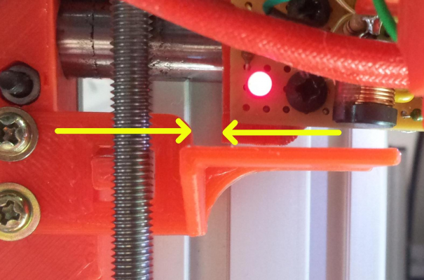
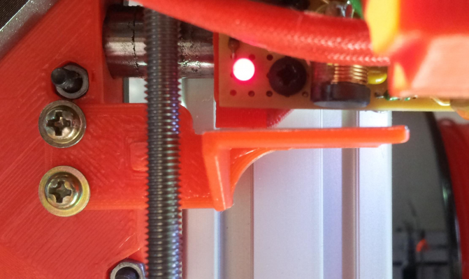
However, for X homing I have an overshoot problem as the time-constant for my PWM filter is 10ms and while the trigger point is well positioned on the sensor tab (if I step it here slowly - position shown in photo) - the homing motion overshoots and hits the end for a brief time (about 5 steps by the sound of it) before moving back to the trigger point.
The problem is that I have the inductor further along the X axis to keep it away from the edge of the bed so the carriage has to come further back to reach the trigger point.
The inductor only has to get it's full diameter onto the tab (covered in aluminium foil) to meet the trigger threshold (red LED on) but the tab shoulder gets hit by the bottom of the X carriage in the 10 or so milliseconds it takes for the level to charge up.
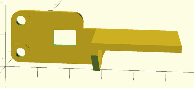
I guess I either extend the tab (easy thanks to David's scad design) but that loses me some table - or redesign it to eliminate the shoulder. I don't want to shorten the filter TC.
RS Components Reprap Ormerod No. 481
|
Re: Inductive Z-height sensing May 14, 2015 01:36PM |
Registered: 10 years ago Posts: 2,472 |
|
Re: Inductive Z-height sensing May 14, 2015 02:08PM |
Registered: 10 years ago Posts: 300 |
Quote
dmould
Extending the tab need not lose you any table - just set the X trigger position as being X=10 (or whatever) in the X homing file macro.
Dave
Unfortunately it's still a mechanical clearance - I didn't describe it too well when I talked about the carriage hitting the "shoulder". This should show you the restricted travel between the two parts:
I've now modded the sensor tab to pull the problem "shoulder" back a few mm:
Edited 1 time(s). Last edit at 05/14/2015 02:18PM by Radian.
RS Components Reprap Ormerod No. 481
|
Re: Inductive Z-height sensing May 14, 2015 03:35PM |
Registered: 10 years ago Posts: 1,230 |
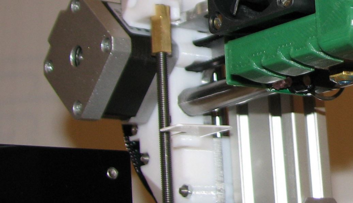
Call me a cheat, I just cut a strip of plastic and super glued it to the original tab :-)
Nice to see you got your inductive sensor working!, I noted dmould wrote that ABS slurry sticks very well to aluminum, far better than on glass, so might be the best option to get an accurate zero reading on ABS slurry with a aluminum bed used instead of glass - not that I have any problem with Davids sensor that is
Erik
Sorry, only registered users may post in this forum.
