Increasing bed temperature
Posted by bartdietrich
|
Increasing bed temperature October 26, 2015 02:35PM |
Registered: 9 years ago Posts: 106 |
Hi all,
We will be attempting to print with POM (polyformaldehyde/polyacetal/acetal/polyoxymethylene). It needs to be POM because of its inertness to chlorinated solvents. We want to print NMR spinners and since chloroform is the most commonly used NMR solvent, we don't want spillages to start dissolving and sticking the spinner to the inside of the probe (could be extremely expensive and disruptive to the service to fix)...
The internet says bed temperature for POM needs to be 120-130 deg C but the highest temperature I can get to is about 112 deg C (and that takes an hour or more).
I understand that the bed gets the full 12V from the supply so there's not much we can do there. The idea is to attach the bed to a variable supply (slowly ramped up from 12V until target temperature is reached) and use the original 12V lines to control the external supply via relay or semiconductor switch (assuming the bed is only ever either on or off and not modulated in any way). The question is, what sort of temperature/current is the bed rated for? Will I break anything if I power the bed with more than 12V and how high could I go to?
Has anyone printed POM? Does the bed need to be that hot? Any other useful info?
Cheers,
Bart
Edited 3 time(s). Last edit at 10/26/2015 03:58PM by bartdietrich.
|
Re: Increasing bed temperature October 26, 2015 05:49PM |
Registered: 10 years ago Posts: 14,672 |
If you have an Ormerod 2, or you have an Ormerod 1 and you have replaced the ATX PSU with a LED PSU, you can use the potentiometer on the PSU to turn the voltage up to about 14V and get extra heating power. The only components that might not like having more than 12V are the fans, so you might want to connect a couple of silicon diodes in series with them to drop the voltage a bit.
Take care not to exceed the total wattage of the PSU if you do this.
Large delta printer [miscsolutions.wordpress.com], E3D tool changer, Robotdigg SCARA printer, Crane Quad and Ormerod
Disclosure: I design Duet electronics and work on RepRapFirmware, [duet3d.com].
Take care not to exceed the total wattage of the PSU if you do this.
Large delta printer [miscsolutions.wordpress.com], E3D tool changer, Robotdigg SCARA printer, Crane Quad and Ormerod
Disclosure: I design Duet electronics and work on RepRapFirmware, [duet3d.com].
|
Re: Increasing bed temperature October 27, 2015 04:16AM |
Registered: 9 years ago Posts: 106 |
Ok thanks, that sounds like a good idea. I seem to remember seeing a potentiometer on the back of the PSU when assembling the Ormerod 2 and wondering whether that's what it was for.
So neither the Duet nor your hot end board will mind the increased voltage?
Just in case that isn't enough and we go with the external power supply, have you got a figure for the absolute maximum voltage the bed can take?
Cheers,
Bart
So neither the Duet nor your hot end board will mind the increased voltage?
Just in case that isn't enough and we go with the external power supply, have you got a figure for the absolute maximum voltage the bed can take?
Cheers,
Bart
|
Re: Increasing bed temperature October 27, 2015 06:14AM |
Registered: 12 years ago Posts: 1,611 |
See the ABS troubleshooting guide for lots of information about getting higher temperatures, and safe limits for the PSU voltage: [reprappro.com]
I wish more people would point this out!
Ian
RepRapPro tech support
I wish more people would point this out!
Ian
RepRapPro tech support
|
Re: Increasing bed temperature October 27, 2015 08:02AM |
Registered: 10 years ago Posts: 1,230 |
|
Re: Increasing bed temperature October 27, 2015 08:54AM |
Registered: 10 years ago Posts: 2,472 |
Quote
bartdietrich
Ok thanks, that sounds like a good idea. I seem to remember seeing a potentiometer on the back of the PSU when assembling the Ormerod 2 and wondering whether that's what it was for.
So neither the Duet nor your hot end board will mind the increased voltage?
Just in case that isn't enough and we go with the external power supply, have you got a figure for the absolute maximum voltage the bed can take?
Cheers,
Bart
The Duet is fine up to any voltage you would want to supply to the bed (IIRC it's rated at 35V). However, if you have a Ormerod 2 with the separate analogue 5V regulator, a significantly higher voltage may exceed the wattage of that regulator. My solution would be to disconnect the regulator output and enable the jumper for the Duet's on-board 5V regulator. That was not used for the Ormerod 2 because it is a switching regulator that emits too much EMI to pass CE approval, but otherwise it works fine. As David says, the only other component to worry about if you increase the voltage is the fan(s), though I took a chance and my fan has been running fine for well over a year (and lots of use) on a 14V supply. I print ABS with a bed temperature of 110 deg C, and with the 14V supply it takes 5 minutes or so to get to temperature, so I should think you could achieve 120 deg with a 14V supply, which should be within the range of the PSU adjustment. The bed will heat faster if you cover it with corrugated cardboard or some other heat insulator whilst it is heating.
Dave
|
Re: Increasing bed temperature October 27, 2015 03:17PM |
Registered: 9 years ago Posts: 106 |
|
Re: Increasing bed temperature November 01, 2015 03:23PM |
Registered: 9 years ago Posts: 106 |
Hi all,
So as promised (or threatened), here's an update.
I increased the power supply voltage to 13.5V and I can now get to 125 deg C (although it still takes 20 or so minutes without covering the bed). The ABS temperature (I use 105 deg C, only recently diversified into ABS from PLA, if anyone thinks I should be using 110 instead then please tell me) is reached in 10-15 minutes. Still a bit of a wait but nothing like the 40-odd minutes it was with 12V.
The hot end fan is not the original that came with the kit (that died a long time ago). The replacement is rated for up to 13.5V (or 13.8V? Don't remember but I checked) so presumably will be fine.
As for the voltage regulator, I just left it as it was. The thought of having to disconnect all the wiring and remove the whole Duet from its enclosure to be able to disconnect the 5V regulator board was rather unappealing and was the major driver in this decision. Hopefully it is not operating at its current limit on 12V so won't mind a little bit more heat dissipation. 7805s are rated for 30-odd volts anyway aren't they?
Thanks everyone for your help!
Bart
|
Re: Increasing bed temperature November 01, 2015 08:25PM |
Registered: 9 years ago Posts: 1,699 |
Linear regulators have to "burn" out the uneccessary voltage that means they convert the uneccessary volatge into heat and send it to the environment. This is called amount of heat to be dissipated. That is why they are very ineffective. The higher the input voltage the higher the heating temperature. This part can only handle a specified temperature. You can use a heatsink if you have higher currents for better heat dissipation. So even if you use a heatsink you cannot reach the fully current output if the input voltage is too high. If you use no heatsink like the supplied PCB board the among of current is much less and depends very strong from the input voltage.
Therefore you can find inside the datasheets diagrams how much power the regulator can handle. There is also a given curve of the maximal power dissipiation. So you have to check individually if you breach that curve. I do not know exactly how much power the Duet needs, but this can maybe be critical. It will not handle 30V without a heatsink. But the regulator is as fas as I know euipped with an overheat shutdown.
I took a look at the datasheet: without heatsink it only can handle 2.5 Watts in the summer. So you have 8.5V that needs to be dissipated that means your line regulator can only handle 294 milliAmps.
[www.ti.com]
Slicer: Simplify3D 4.0; sometimes CraftWare 1.14 or Cura 2.7
Delta with Duet-WiFi, FW: 1.20.1RC2; mini-sensor board by dc42 for auto-leveling
Ormerod common modifications: Mini-sensor board by dc42, aluminum X-arm, 0.4 mm nozzle E3D like, 2nd fan, Z stepper nut M5 x 15, Herringbone gears, Z-axis bearing at top, spring loaded extruder with pneumatic fitting, Y belt axis tensioner
Ormerod 2: FW: 1.19-dc42 on Duet-WiFi. own build, modifications: GT2-belts, silicone heat-bed, different motors and so on. Printed parts: bed support, (PSU holder) and Y-feet.
Ormerod 1: FW: 1.15c-dc42 on 1k Duet-Board. Modifications: Aluminium bed-support, (nearly) all parts reprinted in PLA/ ABS, and so on.
|
Re: Increasing bed temperature November 02, 2015 03:30AM |
Registered: 9 years ago Posts: 106 |
I know how 78xx voltage regulators work, thank you. My point (perhaps not expressed too well in my last post) was that a sensible design would not call for the regulator to operate right at the limit of what it can handle and would include a safety margin. So by increasing the voltage by a mere 10% I would hopefully still be within what the regulator can safely dissipate as heat. And as you say, the 78/79 series have over-current and over-temperature protection so if I start getting unreliable operation of the Duet I'll think about adding a heat sink. This is an example of a Fermi problem and I'm quite good at those. Some would call it "cutting corners" but if it works then don't knock it! :-)
|
Re: Increasing bed temperature November 02, 2015 03:47AM |
Registered: 10 years ago Posts: 14,672 |
Bear in mind that if the 5V regulator does overheat, the voltage on the 5V rail will drop. This will reduce the gate drive to the mosfets, which will cause them to run hotter. Eventually the heated bed mosfet may fail. This is a common scenario with Arduino/RAMPS electronics.
Therefore, if you increase the supply voltage, I recommend that you keep track of the temperature of the 7805.
Large delta printer [miscsolutions.wordpress.com], E3D tool changer, Robotdigg SCARA printer, Crane Quad and Ormerod
Disclosure: I design Duet electronics and work on RepRapFirmware, [duet3d.com].
|
Re: Increasing bed temperature November 26, 2015 05:54PM |
Registered: 9 years ago Posts: 106 |
Hi all,
Apologies for the delay in responding but work got in the way. Also, the following took a bit of time to do. Following all the replies here, I was a bit concerned about ruining my Duet, or at least hastening its demise if I use it with the ramped-up power supply voltage. In particular, dc42's message about the 7805 overheating, dropping its output voltage and leading to other bits failing prematurely was worrying.
Long story short, it doesn't look like there's much to worry about. For the long story, keep reading as the geekiness is strong with this one. I made a bit of a project out of this...
What I needed to do is monitor the output voltage and temperature of the 7805 over the duration of a print.
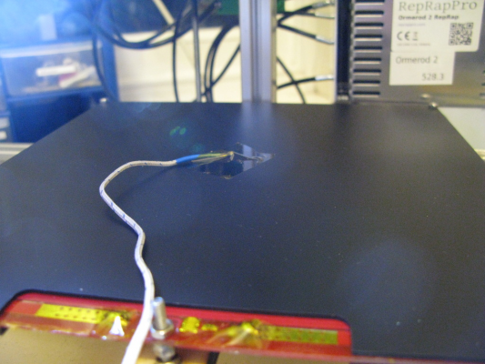
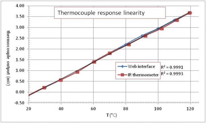
I had a thermocouple knocking about. How linear is its response over the temperature range of interest? For a temperature reference I had the temperature reported by the web interface from the bed thermistor and an infrared (IR) thermometer. My bed heat spreader is painted matte black (for dc42's Z probe) so no issues with dodgy readings from IR thermometer on reflective surfaces. The readings from both the thermistor and IR thermometer followed each other closely enough so the web interface temperature readings were chosen as an accurate enough reference. The thermocouple was taped to the middle of the heat spreader above the thermistor, covered with a piece of bubble wrap for thermal insulation and weighed down.
It turns out its response is linear enough (measured with a HP 3478A benchtop multimeter):
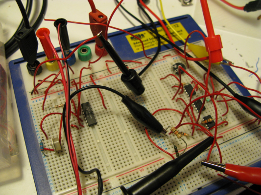
For recording the temperature over the duration of a print, I had a Hantek 6022 USB oscilloscope. The voltages returned by the thermocouple were too low to be accurately measured by the DSO, so I cobbled together an amplifier for it (using an LM324 dual opamp). As for monitoring the output voltage of the 7805, I would be measuring very small variations with a large zero offset, so again the DSO would not be particularly accurate for that (especially since it has a vertical resolution of 8 bit). To maximize dynamic range usage of the DSO, I cobbled together an instrumentation amplifier (using 3 uA741 opamps). This was setup so that the voltage range of roughly 4.3 to 5.1 volts would be mapped to the range -800 to +800 mV. The DSO channel would be set to 200 mV/division, and with the DSO's vertical range of 8 divisions this would give maximal sensitivity over the range of interest. It wasn't pretty but it worked:
The voltage reference for the instrumentation amplifier was a high stability TET Electronic Argos power supply:
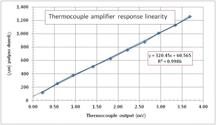
Was the thermocouple amplifier response proportional to the thermocouple potential? Yes:
From that, I got the temperature calibration curve. The reciprocal of the trend line fit equation was used to calculate the temperature of the 7805 later:
Was the instrumentation amplifier response proportional to the input voltage? Yes, and from that we have the voltage calibration curve. The reciprocal of the best fit equation was used to calculate the output voltage from the 7805 later:
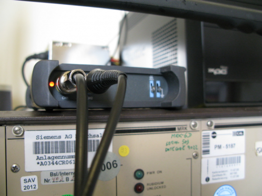
So far, so good. Unfortunately it turned out the software that came with the DSO would not record any waveforms longer than 1 second (even though it has horizontal timebase settings of up to 5000 s/division!). Bug or intentional limitation, I don't know but this would be pretty useless for recording data for a long print. Because I can, and because I took the photo, here's a pic of the DSO:
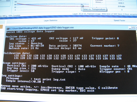
So for the next week and a half I crammed enough C++ (from zero) and deciphered the minimally documented and poorly translated (from Chinese) SDK that came with the DSO to write a console data logger application. It didn't help that the SDK was pretty old and written in Visual C++ 6.0, which did not run on Windows 8 (and the SDK did not compile on newer versions of C++), so initially I had to do all the coding in a virtual machine running XP. The source code itself is probably a good example of bad programming practices (procedure oriented, most variables are global and it's a mess generally) but it works:
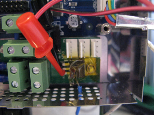
So now to the point of this whole exercise. The thermocouple was taped to the casing of the 7805, hook leads were attached to its output and the case of the Duet was closed.
A short (and poor quality) video of the signal paths:
Signal paths
So my reason for thinking that there's not much to worry about is this:
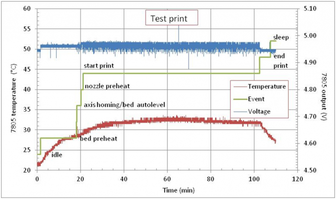
It would appear the 7805 never gets any hotter than 35 deg C and its output voltage does not vary by much over the duration of the print, or drop far below 5 V. Voltage samples were taken every 200 ms (each a series of 256 samples taken at 48 MHz and averaged) so I suppose in theory I could have missed some major dips in voltage but it would seem highly unlikely to have missed all of them, and if they're going to damage downstream components, surely they would happen with great regularity and be more prolonged?
After all this, I'm thinking of going back to an idea I mentioned earlier on in the thread and reducing the printer's power supply voltage back to 12 V after all. The bed would be powered from an external 13.8 V power supply I have lying around gathering dust (how much current does the bed draw??) and controlled via a 12 V relay (and flyback diode just in case) by the original bed cable from the Duet. Why? Because a) I can, b) I don't want to make life too hard for the printer's power supply especially since I'll be adding a second extruder soon.
Phew, can I go to the pub now??
Bart
Apologies for the delay in responding but work got in the way. Also, the following took a bit of time to do. Following all the replies here, I was a bit concerned about ruining my Duet, or at least hastening its demise if I use it with the ramped-up power supply voltage. In particular, dc42's message about the 7805 overheating, dropping its output voltage and leading to other bits failing prematurely was worrying.
Long story short, it doesn't look like there's much to worry about. For the long story, keep reading as the geekiness is strong with this one. I made a bit of a project out of this...
What I needed to do is monitor the output voltage and temperature of the 7805 over the duration of a print.
I had a thermocouple knocking about. How linear is its response over the temperature range of interest? For a temperature reference I had the temperature reported by the web interface from the bed thermistor and an infrared (IR) thermometer. My bed heat spreader is painted matte black (for dc42's Z probe) so no issues with dodgy readings from IR thermometer on reflective surfaces. The readings from both the thermistor and IR thermometer followed each other closely enough so the web interface temperature readings were chosen as an accurate enough reference. The thermocouple was taped to the middle of the heat spreader above the thermistor, covered with a piece of bubble wrap for thermal insulation and weighed down.
It turns out its response is linear enough (measured with a HP 3478A benchtop multimeter):
For recording the temperature over the duration of a print, I had a Hantek 6022 USB oscilloscope. The voltages returned by the thermocouple were too low to be accurately measured by the DSO, so I cobbled together an amplifier for it (using an LM324 dual opamp). As for monitoring the output voltage of the 7805, I would be measuring very small variations with a large zero offset, so again the DSO would not be particularly accurate for that (especially since it has a vertical resolution of 8 bit). To maximize dynamic range usage of the DSO, I cobbled together an instrumentation amplifier (using 3 uA741 opamps). This was setup so that the voltage range of roughly 4.3 to 5.1 volts would be mapped to the range -800 to +800 mV. The DSO channel would be set to 200 mV/division, and with the DSO's vertical range of 8 divisions this would give maximal sensitivity over the range of interest. It wasn't pretty but it worked:
The voltage reference for the instrumentation amplifier was a high stability TET Electronic Argos power supply:
Was the thermocouple amplifier response proportional to the thermocouple potential? Yes:
From that, I got the temperature calibration curve. The reciprocal of the trend line fit equation was used to calculate the temperature of the 7805 later:
Was the instrumentation amplifier response proportional to the input voltage? Yes, and from that we have the voltage calibration curve. The reciprocal of the best fit equation was used to calculate the output voltage from the 7805 later:
So far, so good. Unfortunately it turned out the software that came with the DSO would not record any waveforms longer than 1 second (even though it has horizontal timebase settings of up to 5000 s/division!). Bug or intentional limitation, I don't know but this would be pretty useless for recording data for a long print. Because I can, and because I took the photo, here's a pic of the DSO:
So for the next week and a half I crammed enough C++ (from zero) and deciphered the minimally documented and poorly translated (from Chinese) SDK that came with the DSO to write a console data logger application. It didn't help that the SDK was pretty old and written in Visual C++ 6.0, which did not run on Windows 8 (and the SDK did not compile on newer versions of C++), so initially I had to do all the coding in a virtual machine running XP. The source code itself is probably a good example of bad programming practices (procedure oriented, most variables are global and it's a mess generally) but it works:
So now to the point of this whole exercise. The thermocouple was taped to the casing of the 7805, hook leads were attached to its output and the case of the Duet was closed.
A short (and poor quality) video of the signal paths:
Signal paths
So my reason for thinking that there's not much to worry about is this:
It would appear the 7805 never gets any hotter than 35 deg C and its output voltage does not vary by much over the duration of the print, or drop far below 5 V. Voltage samples were taken every 200 ms (each a series of 256 samples taken at 48 MHz and averaged) so I suppose in theory I could have missed some major dips in voltage but it would seem highly unlikely to have missed all of them, and if they're going to damage downstream components, surely they would happen with great regularity and be more prolonged?
After all this, I'm thinking of going back to an idea I mentioned earlier on in the thread and reducing the printer's power supply voltage back to 12 V after all. The bed would be powered from an external 13.8 V power supply I have lying around gathering dust (how much current does the bed draw??) and controlled via a 12 V relay (and flyback diode just in case) by the original bed cable from the Duet. Why? Because a) I can, b) I don't want to make life too hard for the printer's power supply especially since I'll be adding a second extruder soon.
Phew, can I go to the pub now??

Bart
|
Re: Increasing bed temperature November 27, 2015 03:01AM |
Registered: 10 years ago Posts: 14,672 |
Looks good! I would have just put my finger on the 7805. The Fisher and Huxley kits run the Duet and 7805 from 19V, so there should be no problem with increasing supply voltage somewhat above 12V as long as you don't add any external loads on the 5V or 3.3V rails.
[EDIT: I just remembered that the Fisher doesn't have the 7805, it uses the Duet on-board switching regulator. But the Huxley does power the 7805 from 19V.]
Edited 1 time(s). Last edit at 11/27/2015 03:58AM by dc42.
Large delta printer [miscsolutions.wordpress.com], E3D tool changer, Robotdigg SCARA printer, Crane Quad and Ormerod
Disclosure: I design Duet electronics and work on RepRapFirmware, [duet3d.com].
|
Re: Increasing bed temperature November 27, 2015 03:39AM |
Registered: 9 years ago Posts: 106 |
|
Re: Increasing bed temperature November 27, 2015 07:49AM |
Registered: 10 years ago Posts: 2,472 |
Well ... the word "overkill" did come to mind a couple of times while reading your post :-)
Regarding changing only the bed voltage: The bed is switched by a MOSFET on the ground side of the bed, so ISTM that you could simply remove the + side of the bed (which is usually connected directly to the 12V supply), and connect it to your higher voltage supply instead - it will not require an additional relay. The only fly in the ointment is that the switched side of the bed is also connected to the cathode of an on-board LED, which goes to 12V via a resistor. So when supplying the bed with a higher voltage, the LED will be reverse-biased with a voltage equal to the difference between the higher bed voltage and the Duet 12V supply when the bed is switched off. If the difference is within the max. reverse voltage of the LED you will be OK. If not you could simply remove the LED and/or its resistor (D6 and R65). I do not however see any advantage in powering the bed from a separate supply - as said, the other components on the 12V rail won't mind the additional voltage apart from the fan, which you can drop with a series diode or two if it is an issue (or use a 5V fan powered from the 5V supply).
There is another thread about using a mains voltage bed heater (which heat up PDQ), and switching that via a solid state relay - though in that case you would want to earth all exposed metal and probably power via a RCB for safety.
I've attached the Duet schematic for convenience in case you don't already have it (had to split it due to the file size limitation of this forum), but it is available in the RRP repository.
Dave
|
Re: Increasing bed temperature November 29, 2015 01:57PM |
Registered: 9 years ago Posts: 106 |
Quote
dmould
Well ... the word "overkill" did come to mind a couple of times while reading your post :-)
If it's worth doing, it's worth overdoing. Sometimes. Some things. Well, this particular thing anyway...

Wasn't completely useless though, am quite chuffed with the voltage data logger, it may come in handy for some other geeky project at some point, or maybe even at work. Also, been wanting to learn C++ for years and this made me start. If I can keep up the momentum, maybe I'll finally learn it. Wish I could do the same with Spanish...
Quote
dmould
Regarding changing only the bed voltage: The bed is switched by a MOSFET on the ground side of the bed, so ISTM that you could simply remove the + side of the bed (which is usually connected directly to the 12V supply), and connect it to your higher voltage supply instead - it will not require an additional relay. The only fly in the ointment is that the switched side of the bed is also connected to the cathode of an on-board LED, which goes to 12V via a resistor. So when supplying the bed with a higher voltage, the LED will be reverse-biased with a voltage equal to the difference between the higher bed voltage and the Duet 12V supply when the bed is switched off. If the difference is within the max. reverse voltage of the LED you will be OK. If not you could simply remove the LED and/or its resistor (D6 and R65).
I don't really understand how that would happen? If I cut the positive connection to the bed (which is always at +12V) and replace it with the +13.8V from the external supply, and connect the minus of the external supply to common ground in the Duet, the MOSFET would be powering the bed simply by completing a circuit between common ground and the +13.8V when it's on, and leave an open circuit otherwise. Or am I misunderstanding something?
Even if this situation did arise I don't think it would be a problem anyway. The bed has two LEDs in antiparallel (to accommodate plugging the bed in either way around) so one of them is always reverse-biased at about 1.9 V while the other is lit. This is slightly more than the difference between 12 V and the external power supply I was going to use.
Quote
dmould
I do not however see any advantage in powering the bed from a separate supply - as said, the other components on the 12V rail won't mind the additional voltage apart from the fan, which you can drop with a series diode or two if it is an issue (or use a 5V fan powered from the 5V supply).
It turns out I won't be doing this anyway. The bed draws over 11 A at 13.5 V and my power supply is only rated at 2 A continuous! It's good to know though that I won't be ruining anything too much by having increased the supply to 13.5 V. I hear a replacement Duet is not the cheapest part of the printer.
New development: I may even be able to drop the power supply voltage back to 12 V and still get to 100+ deg C in a reasonable time! I had noticed quite a while ago that one of the bed connectors was getting extremely hot where it connected to the through-PCB screw (to the point of blackening the Kapton tape I had over it). Presumably a dodgy connection. Putting conductive silver paint or even solder over the contacts didn't help. I've been putting off sorting this out for ages (because I'm lazy and the printer was nicely calibrated and I didn't want to have to do all the calibration malarkey again). But today I finally took the bed apart, removed the screws altogether and simply soldered wire from the bed cable contacts to the exposed bits of trace on the top of the bed. The contacts no longer heat up to stupid temperatures and the bed reached 105 deg C in less than 5 minutes!! Should've done that earlier probably...
Quote
dmould
I've attached the Duet schematic for convenience in case you don't already have it (had to split it due to the file size limitation of this forum), but it is available in the RRP repository.
Many thanks for that, didn't know this was available! Will definitely come in handy when I decide to fix more things that don't need fixing. Actually, it may make this more likely so maybe you shouldn't have shared that with me...

Bart
Edited 1 time(s). Last edit at 11/29/2015 01:59PM by bartdietrich.
|
Re: Increasing bed temperature November 29, 2015 02:34PM |
Registered: 9 years ago Posts: 106 |
PS: the two antiparallel LEDs on the bed don't appear on the schematics you posted but my bed has them. They light up in alternate when you reverse the bed polarity. Dual function presumably: to allow connecting the bed either way round and still have one light up, and to protect each other from reverse breakdown.
Bart
Edited 1 time(s). Last edit at 11/29/2015 02:43PM by bartdietrich.
Bart
Edited 1 time(s). Last edit at 11/29/2015 02:43PM by bartdietrich.
|
Re: Increasing bed temperature November 30, 2015 07:22AM |
Registered: 10 years ago Posts: 2,472 |
Quote
bartdietrich
PS: the two antiparallel LEDs on the bed don't appear on the schematics you posted but my bed has them. They light up in alternate when you reverse the bed polarity. Dual function presumably: to allow connecting the bed either way round and still have one light up, and to protect each other from reverse breakdown.
Bart
The bed is not part of the Duet PCB so does not appear on the schematic (the bed driver & connector is on page 6 of the PDF). The LED I was talking about is the LED mounted on the Duet board itself, not the LEDs actually on the bed. That one is connected to the Duet 12V rail so will be reverse-biased if you feed the bed with a higher voltage. You probably will not have noticed them if your Duet is in a case, but it has SMD LEDs that come on with the bed and hotend heaters.
Dave
|
Re: Increasing bed temperature November 30, 2015 08:06AM |
Registered: 9 years ago Posts: 106 |
Quote
dmould
Quote
bartdietrich
PS: the two antiparallel LEDs on the bed don't appear on the schematics you posted but my bed has them. They light up in alternate when you reverse the bed polarity. Dual function presumably: to allow connecting the bed either way round and still have one light up, and to protect each other from reverse breakdown.
Bart
The bed is not part of the Duet PCB so does not appear on the schematic (the bed driver & connector is on page 6 of the PDF). The LED I was talking about is the LED mounted on the Duet board itself, not the LEDs actually on the bed. That one is connected to the Duet 12V rail so will be reverse-biased if you feed the bed with a higher voltage. You probably will not have noticed them if your Duet is in a case, but it has SMD LEDs that come on with the bed and hotend heaters.
Dave
Ah ok, makes more sense now.
It's a moot point now since I won't be doing it anyway, but in my understanding, this shouldn't have been an issue. The Duet LEDs are presumably same or similar type to the bed LEDs and one of the bed LEDs is always reverse biased at the voltage drop of its neighbour, which is 1.9 V. The difference between 12 V and the supply I was going to use is 1.8 V and in any case, surely all respectable LEDs have reverse breakdown ratings of at least 4-5 V anyway, or am I completely wrong? Also, isn't reverse breakdown not necessarily fatal if the current is limited (as it would have been by the LED's series resistor)?
Thanks for all your help,
Bart
Sorry, only registered users may post in this forum.
