How to wire up a Duet 0.8.5?
Posted by 0x0000
|
How to wire up a Duet 0.8.5? January 17, 2016 02:50AM |
Registered: 8 years ago Posts: 164 |
Hey all, I took the plunge and have a Duet 0.8.5 on the way (yay!). I've noticed that the board from T3P3 doesn't use the 5V regulator that the Replikeo board was using. Do I need to use that, or can I go without it? Do I just run the 12V leads from the power supply into the 12V on the Duet? Otherwise, it looks like it's a fairly direct replacement for the 0.6 - are there any gotchas or subtle differences in the wiring that I need to be aware of?
At the moment, my power supply and Duet are wired up but just sitting on my desk. This isn't great even as a short term arrangement, but I need to print the parts I need to complete the build. I'm building my O2 from scratch, and unfortunately I do not have the stainless steel Duet enclosure or the new power supply from RRP (I'm using the one shown in their 528.0 and 528.1 instructions). I'm pretty sure I can get the power supply mounted to the printer following the documentation, but what can I do about the Duet? I've seen a few Duet enclosures up on Thingiverse, but is there a printed part that fits on the back of the supply? Otherwise, I noticed the Duet is mounted on the other side of the original Ormerod - is there any reason I can't do this for the new printer, using one of the printed enclosures?
Edited 1 time(s). Last edit at 01/17/2016 03:03AM by 0x0000.
|
Re: How to wire up a Duet 0.8.5? January 17, 2016 04:15AM |
Registered: 10 years ago Posts: 14,672 |
The reason why RRP used a metal enclosure and an external 5V regulator for the Duet, and shielded cables everywhere, was so that they could claim CE certification for a completed printer assembled as instructed. Otherwise the EMI generated was too high to be certifiable. Assuming CE certification isn't important to you, you can use a printed enclosure as the Ormerod 1 did. You can enable the Duet on-board switching regulator by putting a jumper across the pins labelled 5V_EN (not the ones labelled 5V_ATX_EN). The Duet 0.8.5 regulator produces less EMI than the 0.6 does.
Edited 1 time(s). Last edit at 01/17/2016 04:16AM by dc42.
Large delta printer [miscsolutions.wordpress.com], E3D tool changer, Robotdigg SCARA printer, Crane Quad and Ormerod
Disclosure: I design Duet electronics and work on RepRapFirmware, [duet3d.com].
Edited 1 time(s). Last edit at 01/17/2016 04:16AM by dc42.
Large delta printer [miscsolutions.wordpress.com], E3D tool changer, Robotdigg SCARA printer, Crane Quad and Ormerod
Disclosure: I design Duet electronics and work on RepRapFirmware, [duet3d.com].
|
Re: How to wire up a Duet 0.8.5? January 18, 2016 03:47AM |
Registered: 9 years ago Posts: 92 |
|
Re: How to wire up a Duet 0.8.5? January 18, 2016 04:20AM |
Registered: 8 years ago Posts: 164 |
Quote
steve0-uk
I am working on an enclosure based on the O2 For the 0.8.5 duet with a lid to mount a cooling fan. However it is untested.
I am willing to release the stl if anyone wants to try it
I'd be keen to try it, though it'd have to be one of my first prints! Would it mount on the back of the power supply, rather than using the steel enclosure? How big is the fan?
|
Re: How to wire up a Duet 0.8.5? January 18, 2016 05:54AM |
Registered: 9 years ago Posts: 92 |
Quote
0x0000
Quote
steve0-uk
I am working on an enclosure based on the O2 For the 0.8.5 duet with a lid to mount a cooling fan. However it is untested.
I am willing to release the stl if anyone wants to try it
I'd be keen to try it, though it'd have to be one of my first prints! Would it mount on the back of the power supply, rather than using the steel enclosure? How big is the fan?
It's has been extended to mount as the O2 would have but haven't got the mounting holes for the plate just for the duet. I planned to use a different way of cable connections from the duet to the outside of the enclosure. I haven't cut the slots for the fan as yet. I'll upload a pic when I get home
|
Re: How to wire up a Duet 0.8.5? January 18, 2016 12:36PM |
Registered: 9 years ago Posts: 92 |
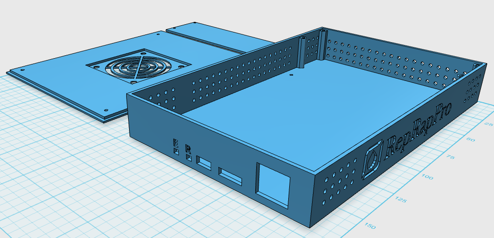
here is a screen grab of what i am working on
my plan with the bottom is split the lid in two and the lower section have plug in circular connectors for all the wires instead of having them all come out the side. similar to the Lulzbot Taz as shown here
[i-t-w.com]
then mount a cooling fan in the top half of the lid, probably 40-50 mm in size added to one of the always on fan connectors
i am working on another that is just the size of the duet but is only a box with a few air holes in
|
Re: How to wire up a Duet 0.8.5? January 19, 2016 04:41AM |
Registered: 8 years ago Posts: 164 |
|
Re: How to wire up a Duet 0.8.5? January 19, 2016 04:48AM |
Registered: 9 years ago Posts: 92 |
Quote
0x0000
That looks great! I love the circular connectors - they would come in really handy if you ever had to move the Duet to another printer, or swap it out. Wiring might be a pain, but you'd only have to do it once!
thanks its taken ages to do all those holes, the logo was particularly difficult...
I spent some time on it last night, working on the 50mm cooling fan in the lid at the moment, then I will upload it for you to try out
|
Re: How to wire up a Duet 0.8.5? January 19, 2016 04:59AM |
Registered: 8 years ago Posts: 164 |
|
Re: How to wire up a Duet 0.8.5? January 19, 2016 05:15AM |
Registered: 9 years ago Posts: 1,159 |
Quote
steve0-uk
Quote
0x0000
That looks great! I love the circular connectors - they would come in really handy if you ever had to move the Duet to another printer, or swap it out. Wiring might be a pain, but you'd only have to do it once!
thanks its taken ages to do all those holes, the logo was particularly difficult...
I spent some time on it last night, working on the 50mm cooling fan in the lid at the moment, then I will upload it for you to try out
The best positioning for a Fan for the duet's is in the end of the enclosure so that cooling air flow's in line with the Stepper's and across both top and bottom surface of the board. The stepper driver chips are cooled by the underside of them and the board itself.
Also to note those Mil spec circular connectors in the TazBot are an absolute pain to assemble if you don't have the correct tooling (I am an EX Military Avionics Engineer).
HTH
Doug
Edited 1 time(s). Last edit at 01/19/2016 05:17AM by dougal1957.
|
Re: How to wire up a Duet 0.8.5? January 19, 2016 08:47AM |
Registered: 9 years ago Posts: 92 |
Quote
dougal1957
Quote
steve0-uk
Quote
0x0000
That looks great! I love the circular connectors - they would come in really handy if you ever had to move the Duet to another printer, or swap it out. Wiring might be a pain, but you'd only have to do it once!
thanks its taken ages to do all those holes, the logo was particularly difficult...
I spent some time on it last night, working on the 50mm cooling fan in the lid at the moment, then I will upload it for you to try out
The best positioning for a Fan for the duet's is in the end of the enclosure so that cooling air flow's in line with the Stepper's and across both top and bottom surface of the board. The stepper driver chips are cooled by the underside of them and the board itself.
Also to note those Mil spec circular connectors in the TazBot are an absolute pain to assemble if you don't have the correct tooling (I am an EX Military Avionics Engineer).
HTH
Doug
I was going to mount the fan so it sucks out air, there are plenty of holes in the case for air flow
I used to work at RS I know how painful those mil spec ones are, I am using similar ones but are not mil spec. I have the correct crimp tool for the ones I am using

|
Re: How to wire up a Duet 0.8.5? January 19, 2016 12:58PM |
Registered: 9 years ago Posts: 1,159 |
Quote
steve0-uk
Quote
dougal1957
Quote
steve0-uk
Quote
0x0000
That looks great! I love the circular connectors - they would come in really handy if you ever had to move the Duet to another printer, or swap it out. Wiring might be a pain, but you'd only have to do it once!
thanks its taken ages to do all those holes, the logo was particularly difficult...
I spent some time on it last night, working on the 50mm cooling fan in the lid at the moment, then I will upload it for you to try out
The best positioning for a Fan for the duet's is in the end of the enclosure so that cooling air flow's in line with the Stepper's and across both top and bottom surface of the board. The stepper driver chips are cooled by the underside of them and the board itself.
Also to note those Mil spec circular connectors in the TazBot are an absolute pain to assemble if you don't have the correct tooling (I am an EX Military Avionics Engineer).
HTH
Doug
I was going to mount the fan so it sucks out air, there are plenty of holes in the case for air flow
I used to work at RS I know how painful those mil spec ones are, I am using similar ones but are not mil spec. I have the correct crimp tool for the ones I am using
What about Airflow on the underside of the Board there doesn't appear to be any holes underneath that would allow that to Happen (It is the lower surface of the Board that cools the Stepper's)
Don't Get me wrong I like the design apart from the cooling bit

Doug
Edited 1 time(s). Last edit at 01/19/2016 12:59PM by dougal1957.
|
Re: How to wire up a Duet 0.8.5? January 19, 2016 02:24PM |
Registered: 9 years ago Posts: 638 |
I have just got my duet 0.8.5 and i must say the new erase and reset switches are weird ,they seem to get stuck when pushed in. Let me know if your switches are the same.
1st question I have noticed that the Probe will come in diferent place then 0.6:
In the bottom left corner next to paneldue pins ,how do i wire it correctly? I have dc42's dual sensor board
2nd question is the Print cooling fan. I see that this board has a PWM fan pins. On my 0.6 duet i have been using 2N7000 mosfet to wire a 4 wire PWM fan ,i'm wondering how do i wire it to this board?
Wired it acording to this post: [forums.reprap.org]
Main thing can i just use the Ground on the 5V rail next to the 12v input. Since i will be using the onboard 5V controler.
1st question I have noticed that the Probe will come in diferent place then 0.6:

In the bottom left corner next to paneldue pins ,how do i wire it correctly? I have dc42's dual sensor board
2nd question is the Print cooling fan. I see that this board has a PWM fan pins. On my 0.6 duet i have been using 2N7000 mosfet to wire a 4 wire PWM fan ,i'm wondering how do i wire it to this board?
Wired it acording to this post: [forums.reprap.org]
Quote
orictosh
Wiring is as follows
fan's black wire goes to the source on the mosfet
fan's red wire goes to the fan 0 positive connection on the duet board
fan's brown wire goes to the drain on the mosfet
mosfet's gate goes to the negative pin on the fan 0 connection
The mosfet's source conections go to a gound pin on the duet (it's the left pin above the hot end fan connection)
The set of pins is called J6
Chris
Main thing can i just use the Ground on the 5V rail next to the 12v input. Since i will be using the onboard 5V controler.
|
Re: How to wire up a Duet 0.8.5? January 19, 2016 02:39PM |
Registered: 9 years ago Posts: 92 |
Quote
dougal1957
What about Airflow on the underside of the Board there doesn't appear to be any holes underneath that would allow that to Happen (It is the lower surface of the Board that cools the Stepper's)
Don't Get me wrong I like the design apart from the cooling bit
Doug
it's still a work in progress... as for the underside cooling my O2 has the metal case (mine is one of the very first second versions with a fan on top of the PSU) with Kapton tape on the bottom, there is no ventilation on the bottom from that point of view, I just copied from that.
|
Re: How to wire up a Duet 0.8.5? January 19, 2016 02:43PM |
Registered: 9 years ago Posts: 92 |
|
Re: How to wire up a Duet 0.8.5? January 22, 2016 03:13AM |
Registered: 8 years ago Posts: 164 |
My Duet arrived today - along with proper wiring looms and a straight-push connector for my Bowden tube! ! Looking forward to trying out your enclosure, @steve0-uk
Is the RepRapPro logo actually printable? Seems like the closed inner parts of most of the letters (R e p R a p P o and the R in reset) would be made of plastic without any supports?
Is the RepRapPro logo actually printable? Seems like the closed inner parts of most of the letters (R e p R a p P o and the R in reset) would be made of plastic without any supports?
|
Re: How to wire up a Duet 0.8.5? January 22, 2016 06:54AM |
Registered: 9 years ago Posts: 92 |
Quote
0x0000
Is the RepRapPro logo actually printable? Seems like the closed inner parts of most of the letters (R e p R a p P o and the R in reset) would be made of plastic without any supports?
it should print without supports, still not printed one myself yet, I am looking to find parts to build a second one at the moment.
if you want, i'll send you over just the wall with the logo on to test print
Edited 1 time(s). Last edit at 01/22/2016 06:54AM by steve0-uk.
|
Re: How to wire up a Duet 0.8.5? January 24, 2016 12:17AM |
Registered: 8 years ago Posts: 164 |
Has the wiring for the probe changed from 0.6 to 0.8.5? The pins on the new Duet are labeled, but the ones on the proximity sensor are not.
On the Duet 0.6:
Green = 3V3
Yellow = GND
Blue = AD14
Red = AD12
My proximity sensor pins are unlabeled, and the values on the back of the new Duet do not correspond with where I had them plugged in on the old board (following this diagram from RRP). I can't find PC10 anywhere on the old board. If anybody could tell me what each colour does on my picture, I'd appreciate it!
3V3 = ???
PC10 = ???
GND = ???
AD12 = ???
With dedicated pins for the probe, are the extruder endstop pins used for anything else?
Edited 1 time(s). Last edit at 01/24/2016 12:17AM by 0x0000.
On the Duet 0.6:
Green = 3V3
Yellow = GND
Blue = AD14
Red = AD12
My proximity sensor pins are unlabeled, and the values on the back of the new Duet do not correspond with where I had them plugged in on the old board (following this diagram from RRP). I can't find PC10 anywhere on the old board. If anybody could tell me what each colour does on my picture, I'd appreciate it!
3V3 = ???
PC10 = ???
GND = ???
AD12 = ???
With dedicated pins for the probe, are the extruder endstop pins used for anything else?

Edited 1 time(s). Last edit at 01/24/2016 12:17AM by 0x0000.
|
Re: How to wire up a Duet 0.8.5? January 24, 2016 03:28AM |
Registered: 10 years ago Posts: 14,672 |
The 0.8.5 uses a different pin to drive the modulation input to the proximity sensor because AD14 is needed for something else. The firmware is aware of this, just make sure it auto detects the board type correctly by running M115.
Edited 1 time(s). Last edit at 01/24/2016 03:30AM by dc42.
Large delta printer [miscsolutions.wordpress.com], E3D tool changer, Robotdigg SCARA printer, Crane Quad and Ormerod
Disclosure: I design Duet electronics and work on RepRapFirmware, [duet3d.com].
Edited 1 time(s). Last edit at 01/24/2016 03:30AM by dc42.
Large delta printer [miscsolutions.wordpress.com], E3D tool changer, Robotdigg SCARA printer, Crane Quad and Ormerod
Disclosure: I design Duet electronics and work on RepRapFirmware, [duet3d.com].
|
Re: How to wire up a Duet 0.8.5? January 24, 2016 10:34AM |
Registered: 9 years ago Posts: 638 |
Quote
0x0000
Has the wiring for the probe changed from 0.6 to 0.8.5? The pins on the new Duet are labeled, but the ones on the proximity sensor are not.
On the Duet 0.6:
Green = 3V3
Yellow = GND
Blue = AD14
Red = AD12
My proximity sensor pins are unlabeled, and the values on the back of the new Duet do not correspond with where I had them plugged in on the old board (following this diagram from RRP). I can't find PC10 anywhere on the old board. If anybody could tell me what each colour does on my picture, I'd appreciate it!
3V3 = ???
PC10 = ???
GND = ???
AD12 = ???
With dedicated pins for the probe, are the extruder endstop pins used for anything else?
[attachment 70616 IMG_20160124_175740-01.jpeg]
On the back side of the duet they are marked which pin is which
question abaut your board ,are the reset and erase switches toggle or do they get stuck when pressed on your board?
Edited 2 time(s). Last edit at 01/24/2016 11:14AM by Darathy.
|
Re: How to wire up a Duet 0.8.5? January 24, 2016 03:13PM |
Registered: 8 years ago Posts: 164 |
Quote
Darathy
Quote
0x0000
Has the wiring for the probe changed from 0.6 to 0.8.5? The pins on the new Duet are labeled, but the ones on the proximity sensor are not.
On the Duet 0.6:
Green = 3V3
Yellow = GND
Blue = AD14
Red = AD12
My proximity sensor pins are unlabeled, and the values on the back of the new Duet do not correspond with where I had them plugged in on the old board (following this diagram from RRP). I can't find PC10 anywhere on the old board. If anybody could tell me what each colour does on my picture, I'd appreciate it!
3V3 = ???
PC10 = ???
GND = ???
AD12 = ???
With dedicated pins for the probe, are the extruder endstop pins used for anything else?
[attachment 70616 IMG_20160124_175740-01.jpeg]
On the back side of the duet they are marked which pin is which
question abaut your board ,are the reset and erase switches toggle or do they get stuck when pressed on your board?
They don't get stuck, but they're so tiny I don't notice that they've been released. I've only pressed them once though
|
Re: How to wire up a Duet 0.8.5? January 24, 2016 06:55PM |
Registered: 8 years ago Posts: 164 |
|
Re: How to wire up a Duet 0.8.5? January 24, 2016 07:10PM |
Registered: 8 years ago Posts: 164 |
For the DC power source, Think3dPrint3D said the 5V regulator is optional, but I've never seen this wired without the regulator. Is this the correct way to wire the power for the Duet 0.8.5?
Duet
Power supply
My only 5V regulator is from Replikeo and I'd prefer to not use it. It burned the brown wire on my last board, so I suspect it is crap.
Duet

Power supply

My only 5V regulator is from Replikeo and I'd prefer to not use it. It burned the brown wire on my last board, so I suspect it is crap.
|
Re: How to wire up a Duet 0.8.5? January 24, 2016 07:18PM |
Registered: 8 years ago Posts: 164 |
Also, those hotend wires in the screw terminals look way too close for comfort... I've crammed some Kapton tape in there just in case, but I'm not sure what else I can do.
Did I do something wrong, or are my heater wires just abnormally large? That red stuff is woven insulation with some kind of plastic protecting the threaded cable underneath. I've tinned every wire that uses these screw terminals, by the way, and used a proper screwdriver to ensure they're in there good and tight!

Did I do something wrong, or are my heater wires just abnormally large? That red stuff is woven insulation with some kind of plastic protecting the threaded cable underneath. I've tinned every wire that uses these screw terminals, by the way, and used a proper screwdriver to ensure they're in there good and tight!
|
Re: How to wire up a Duet 0.8.5? January 25, 2016 02:04AM |
Registered: 9 years ago Posts: 1,699 |
I am very sorry, but as Electrician I am getting sick if I see such kind of connection. That is very dangerous. You risk a fire. If you use such kind of connection the screws will get loose and the connection is not given anymore and you will get a broken Duet. Such kind of connection is strictly forbidden here in Germany.
If you have a flexible wire you are not allowed to use solder to connect the little wires. that is the worst thing you could do even if you solder it right. You can see that little conductors of your wires are not clamped in. That is the next problem so the diameter of the conductor is not given anymore and this also could cause a short circuit.
Where do you live?
You have to use ending connections like these ones:
[en.glw.de]
Slicer: Simplify3D 4.0; sometimes CraftWare 1.14 or Cura 2.7
Delta with Duet-WiFi, FW: 1.20.1RC2; mini-sensor board by dc42 for auto-leveling
Ormerod common modifications: Mini-sensor board by dc42, aluminum X-arm, 0.4 mm nozzle E3D like, 2nd fan, Z stepper nut M5 x 15, Herringbone gears, Z-axis bearing at top, spring loaded extruder with pneumatic fitting, Y belt axis tensioner
Ormerod 2: FW: 1.19-dc42 on Duet-WiFi. own build, modifications: GT2-belts, silicone heat-bed, different motors and so on. Printed parts: bed support, (PSU holder) and Y-feet.
Ormerod 1: FW: 1.15c-dc42 on 1k Duet-Board. Modifications: Aluminium bed-support, (nearly) all parts reprinted in PLA/ ABS, and so on.
If you have a flexible wire you are not allowed to use solder to connect the little wires. that is the worst thing you could do even if you solder it right. You can see that little conductors of your wires are not clamped in. That is the next problem so the diameter of the conductor is not given anymore and this also could cause a short circuit.
Where do you live?
You have to use ending connections like these ones:

[en.glw.de]
Slicer: Simplify3D 4.0; sometimes CraftWare 1.14 or Cura 2.7
Delta with Duet-WiFi, FW: 1.20.1RC2; mini-sensor board by dc42 for auto-leveling
Ormerod common modifications: Mini-sensor board by dc42, aluminum X-arm, 0.4 mm nozzle E3D like, 2nd fan, Z stepper nut M5 x 15, Herringbone gears, Z-axis bearing at top, spring loaded extruder with pneumatic fitting, Y belt axis tensioner
Ormerod 2: FW: 1.19-dc42 on Duet-WiFi. own build, modifications: GT2-belts, silicone heat-bed, different motors and so on. Printed parts: bed support, (PSU holder) and Y-feet.
Ormerod 1: FW: 1.15c-dc42 on 1k Duet-Board. Modifications: Aluminium bed-support, (nearly) all parts reprinted in PLA/ ABS, and so on.
|
Re: How to wire up a Duet 0.8.5? January 25, 2016 02:33AM |
Registered: 10 years ago Posts: 14,672 |
Quote
0x0000
For the DC power source, Think3dPrint3D said the 5V regulator is optional, but I've never seen this wired without the regulator. Is this the correct way to wire the power for the Duet 0.8.5?
The cable from the PSU to the power input is too thin. You should use cable capable of carrying 20A. I use heavy duty speaker cable. Use ferrules on the ends of the power wires where they go into the terminal block, or use solid core cable.
Large delta printer [miscsolutions.wordpress.com], E3D tool changer, Robotdigg SCARA printer, Crane Quad and Ormerod
Disclosure: I design Duet electronics and work on RepRapFirmware, [duet3d.com].
|
Re: How to wire up a Duet 0.8.5? January 25, 2016 02:36AM |
Registered: 9 years ago Posts: 1,699 |
Or take a look at here:
I use the small one at the top left (but isolated) for the connection of my PSU. The variants on the right side would give a better connection if you use the right diameter for the whole. You can find them at car accessories.
Edit: A nicer one. I use the red one at the upper right corner for the power supply connection and as blue one for the Duet power connection.
[upload.wikimedia.org]
Slicer: Simplify3D 4.0; sometimes CraftWare 1.14 or Cura 2.7
Delta with Duet-WiFi, FW: 1.20.1RC2; mini-sensor board by dc42 for auto-leveling
Ormerod common modifications: Mini-sensor board by dc42, aluminum X-arm, 0.4 mm nozzle E3D like, 2nd fan, Z stepper nut M5 x 15, Herringbone gears, Z-axis bearing at top, spring loaded extruder with pneumatic fitting, Y belt axis tensioner
Ormerod 2: FW: 1.19-dc42 on Duet-WiFi. own build, modifications: GT2-belts, silicone heat-bed, different motors and so on. Printed parts: bed support, (PSU holder) and Y-feet.
Ormerod 1: FW: 1.15c-dc42 on 1k Duet-Board. Modifications: Aluminium bed-support, (nearly) all parts reprinted in PLA/ ABS, and so on.
|
Re: How to wire up a Duet 0.8.5? January 25, 2016 03:08AM |
Registered: 8 years ago Posts: 164 |
Quote
Treito
I am very sorry, but as Electrician I am getting sick if I see such kind of connection. That is very dangerous. You risk a fire. If you use such kind of connection the screws will get loose and the connection is not given anymore and you will get a broken Duet. Such kind of connection is strictly forbidden here in Germany.
If you have a flexible wire you are not allowed to use solder to connect the little wires. that is the worst thing you could do even if you solder it right. You can see that little conductors of your wires are not clamped in. That is the next problem so the diameter of the conductor is not given anymore and this also could cause a short circuit.
Where do you live?
You have to use ending connections like these ones:
[en.glw.de]
Thanks for the reality check Treito! I'm in New Zealand. I'll have a look around for those connectors - Google Translate says "ferrules" which makes sense, but what kind of metal do I need to look for? Is there a particular crimping tool that I need to make them? I soldered the wires this way after following the documentation for the original Ormerod, shown here. As the old saying goes, just because you read it on the Internet, doesn't mean it's true!
I do have some solid-core cabling left over from the IEC fused socket, so I might try that for the power terminal.
Edited 1 time(s). Last edit at 01/25/2016 03:13AM by 0x0000.
|
Re: How to wire up a Duet 0.8.5? January 25, 2016 03:30AM |
Registered: 9 years ago Posts: 1,699 |
In Germany you only get one sort of them. i did not care about the material yet. You can solder a connection if the connection is permanent and not screwed, but you used screwed terminals. But if you solder you have to ensure that the solder encapsulates the whole wire.
For both types are crimping tools available.
Take a look here it is all in the wiki here: [reprap.org]
(Okay, maybe I should not say that it took me a while to find it myself )
)
Here are some pics of my connections. The case for my Duet 0.6 of my MK2 is not ready as I had to commission the printer early after two broken Duet boards and the MK1 is still not fully useable But close.
Slicer: Simplify3D 4.0; sometimes CraftWare 1.14 or Cura 2.7
Delta with Duet-WiFi, FW: 1.20.1RC2; mini-sensor board by dc42 for auto-leveling
Ormerod common modifications: Mini-sensor board by dc42, aluminum X-arm, 0.4 mm nozzle E3D like, 2nd fan, Z stepper nut M5 x 15, Herringbone gears, Z-axis bearing at top, spring loaded extruder with pneumatic fitting, Y belt axis tensioner
Ormerod 2: FW: 1.19-dc42 on Duet-WiFi. own build, modifications: GT2-belts, silicone heat-bed, different motors and so on. Printed parts: bed support, (PSU holder) and Y-feet.
Ormerod 1: FW: 1.15c-dc42 on 1k Duet-Board. Modifications: Aluminium bed-support, (nearly) all parts reprinted in PLA/ ABS, and so on.
For both types are crimping tools available.
Take a look here it is all in the wiki here: [reprap.org]
(Okay, maybe I should not say that it took me a while to find it myself
)Here are some pics of my connections. The case for my Duet 0.6 of my MK2 is not ready as I had to commission the printer early after two broken Duet boards and the MK1 is still not fully useable
But close.


Slicer: Simplify3D 4.0; sometimes CraftWare 1.14 or Cura 2.7
Delta with Duet-WiFi, FW: 1.20.1RC2; mini-sensor board by dc42 for auto-leveling
Ormerod common modifications: Mini-sensor board by dc42, aluminum X-arm, 0.4 mm nozzle E3D like, 2nd fan, Z stepper nut M5 x 15, Herringbone gears, Z-axis bearing at top, spring loaded extruder with pneumatic fitting, Y belt axis tensioner
Ormerod 2: FW: 1.19-dc42 on Duet-WiFi. own build, modifications: GT2-belts, silicone heat-bed, different motors and so on. Printed parts: bed support, (PSU holder) and Y-feet.
Ormerod 1: FW: 1.15c-dc42 on 1k Duet-Board. Modifications: Aluminium bed-support, (nearly) all parts reprinted in PLA/ ABS, and so on.
|
Re: How to wire up a Duet 0.8.5? January 25, 2016 03:52AM |
Registered: 8 years ago Posts: 164 |
Nice work! What size are your ferrules? I just did a quick measurement, and the larger green ones measure approximately 3mm across? The baby ones for the hotend wires on the 0.8.5 are smaller, approximately 1mm
There's an electrical supplies store in the city, I'll see if they stock something more useful than the hobbyist electronic shop.
I'll refrain from showing you my IEC fused socket. It will make you sicker!
Edited 1 time(s). Last edit at 01/25/2016 03:54AM by 0x0000.
There's an electrical supplies store in the city, I'll see if they stock something more useful than the hobbyist electronic shop.
I'll refrain from showing you my IEC fused socket. It will make you sicker!
Edited 1 time(s). Last edit at 01/25/2016 03:54AM by 0x0000.

Sorry, only registered users may post in this forum.