Mounting dc42's Mini height sensor board
Posted by Treito
|
Mounting dc42's Mini height sensor board March 07, 2016 11:48PM |
Registered: 9 years ago Posts: 1,699 |
Good morning,
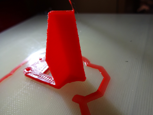
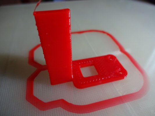
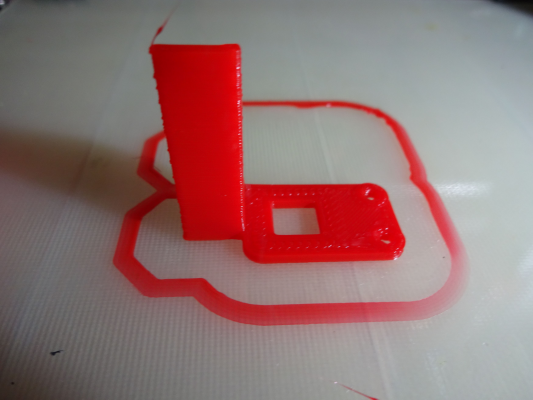
a common problem with this genius mini height sensor board made by dc42 is the mounting to the Ormerod 1 or 2. I created a mounting bracket directly for the x-carriage as replacement for the stock proximity sensor board and tested it so far with my MK1 (including dc42's one-piece-fan-duct). With the stock sensor I have never been able to level the bed exactly. In most cases I was only available to do small printouts. Using dc42's sensor board I get stable height values and I am able to use the bed fully. It is comparable with my MK2 which uses a microswitch triggered by the E3D clone nozzle which will be lifted up when touching the bed. My MK2 will be follow soon as the mechanical method has some bad disadvantages.
So here is the link to the thing:
[www.thingiverse.com]
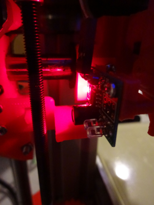
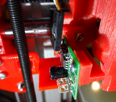
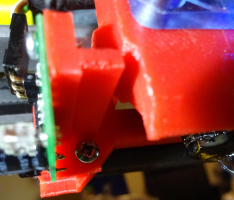
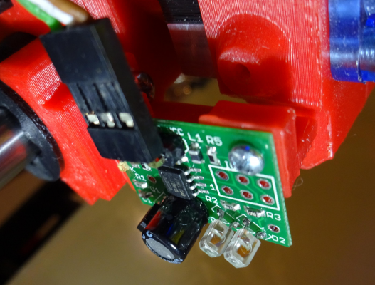
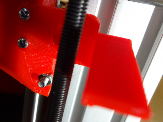
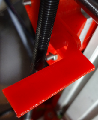
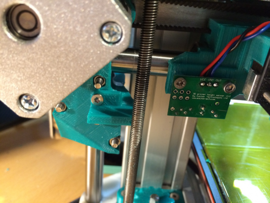
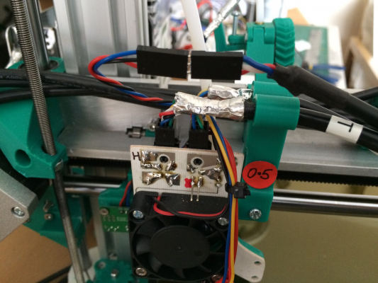
And some pictures. Unfortunately the Sensor pad from dc42 is a little bit too short, I will design a new one sometime later. It is astonishing that the sensor board is working well even though not hitting it completely:
Upper mounting screw:
Lower mounting screw:
Total view:
Edited 1 time(s). Last edit at 03/07/2016 11:49PM by Treito.
Slicer: Simplify3D 4.0; sometimes CraftWare 1.14 or Cura 2.7
Delta with Duet-WiFi, FW: 1.20.1RC2; mini-sensor board by dc42 for auto-leveling
Ormerod common modifications: Mini-sensor board by dc42, aluminum X-arm, 0.4 mm nozzle E3D like, 2nd fan, Z stepper nut M5 x 15, Herringbone gears, Z-axis bearing at top, spring loaded extruder with pneumatic fitting, Y belt axis tensioner
Ormerod 2: FW: 1.19-dc42 on Duet-WiFi. own build, modifications: GT2-belts, silicone heat-bed, different motors and so on. Printed parts: bed support, (PSU holder) and Y-feet.
Ormerod 1: FW: 1.15c-dc42 on 1k Duet-Board. Modifications: Aluminium bed-support, (nearly) all parts reprinted in PLA/ ABS, and so on.
|
Re: Mounting dc42's Mini height sensor board March 09, 2016 01:02AM |
Registered: 9 years ago Posts: 1,699 |
Edit 2: I published a modified version of the sensor pad together with the bracket. See link above. Here are some not commented pictures:
Edited 2 time(s). Last edit at 03/09/2016 03:56AM by Treito.
Slicer: Simplify3D 4.0; sometimes CraftWare 1.14 or Cura 2.7
Delta with Duet-WiFi, FW: 1.20.1RC2; mini-sensor board by dc42 for auto-leveling
Ormerod common modifications: Mini-sensor board by dc42, aluminum X-arm, 0.4 mm nozzle E3D like, 2nd fan, Z stepper nut M5 x 15, Herringbone gears, Z-axis bearing at top, spring loaded extruder with pneumatic fitting, Y belt axis tensioner
Ormerod 2: FW: 1.19-dc42 on Duet-WiFi. own build, modifications: GT2-belts, silicone heat-bed, different motors and so on. Printed parts: bed support, (PSU holder) and Y-feet.
Ormerod 1: FW: 1.15c-dc42 on 1k Duet-Board. Modifications: Aluminium bed-support, (nearly) all parts reprinted in PLA/ ABS, and so on.
|
Re: Mounting dc42's Mini height sensor board March 09, 2016 02:10PM |
Registered: 9 years ago Posts: 638 |
|
Re: Mounting dc42's Mini height sensor board March 09, 2016 10:13PM |
Registered: 9 years ago Posts: 1,699 |
Dc42's sensors need dark and non-reflective colours. The stock sensor needs the white pad.
Slicer: Simplify3D 4.0; sometimes CraftWare 1.14 or Cura 2.7
Delta with Duet-WiFi, FW: 1.20.1RC2; mini-sensor board by dc42 for auto-leveling
Ormerod common modifications: Mini-sensor board by dc42, aluminum X-arm, 0.4 mm nozzle E3D like, 2nd fan, Z stepper nut M5 x 15, Herringbone gears, Z-axis bearing at top, spring loaded extruder with pneumatic fitting, Y belt axis tensioner
Ormerod 2: FW: 1.19-dc42 on Duet-WiFi. own build, modifications: GT2-belts, silicone heat-bed, different motors and so on. Printed parts: bed support, (PSU holder) and Y-feet.
Ormerod 1: FW: 1.15c-dc42 on 1k Duet-Board. Modifications: Aluminium bed-support, (nearly) all parts reprinted in PLA/ ABS, and so on.
|
Re: Mounting dc42's Mini height sensor board March 10, 2016 02:23AM |
Registered: 10 years ago Posts: 14,672 |
The sensors I make are OK with white surfaces too. What they don't like is bright aluminium.
Large delta printer [miscsolutions.wordpress.com], E3D tool changer, Robotdigg SCARA printer, Crane Quad and Ormerod
Disclosure: I design Duet electronics and work on RepRapFirmware, [duet3d.com].
Large delta printer [miscsolutions.wordpress.com], E3D tool changer, Robotdigg SCARA printer, Crane Quad and Ormerod
Disclosure: I design Duet electronics and work on RepRapFirmware, [duet3d.com].
|
Re: Mounting dc42's Mini height sensor board March 10, 2016 03:43AM |
Registered: 9 years ago Posts: 1,699 |
The stock sensor did not work properly with the red surface. I got a reading, but that was about 200 maximum. The sensor board reacts even on a small surface that means nearby the edge. It's amazing.
But it seems to be a little bit dependent from the bed temperature. I had to change the value (height) as I tried to print ABS. I will have to check this behaviour with my MK2 as soon as I can because of the trouble I generally have with my MK1.
But I am really happy that I can print larger objects with my MK1 now.
Slicer: Simplify3D 4.0; sometimes CraftWare 1.14 or Cura 2.7
Delta with Duet-WiFi, FW: 1.20.1RC2; mini-sensor board by dc42 for auto-leveling
Ormerod common modifications: Mini-sensor board by dc42, aluminum X-arm, 0.4 mm nozzle E3D like, 2nd fan, Z stepper nut M5 x 15, Herringbone gears, Z-axis bearing at top, spring loaded extruder with pneumatic fitting, Y belt axis tensioner
Ormerod 2: FW: 1.19-dc42 on Duet-WiFi. own build, modifications: GT2-belts, silicone heat-bed, different motors and so on. Printed parts: bed support, (PSU holder) and Y-feet.
Ormerod 1: FW: 1.15c-dc42 on 1k Duet-Board. Modifications: Aluminium bed-support, (nearly) all parts reprinted in PLA/ ABS, and so on.
|
Re: Mounting dc42's Mini height sensor board May 06, 2016 05:10PM |
Registered: 8 years ago Posts: 45 |
I didn't get on with this solution. I couldn't get the nozzle to the edge of the bed without moving it to the other hole in the quickset heat sink. This the messed up my part cooling as the fan is much further away.
I decided to go down the stock sensor route and mount it on the X carriage. This meant making a small mod to the X carriage as the board is wider and shorter. The capacitor means it's also a bit deeper.
The existing homing tab triggered the sensor, but not reliably enough when homing. So I knocked up a new homing tab, after cutting off the existing one.
I've uploaded my parts to [www.thingiverse.com] if anyone is interested. Note I did have to cut the corner off the carriage in the photo as I didn't account for the motor hitting it... (Corrected in the STL)
It's a bit tight so you will need to use a countersunk screw nearest the Z rod to mount the board.
I have to say the mini sensor board is the bees knees. No more white pads, and setting the Z trigger height with G30 S-1 is a dream. I've also found it's stable enough to use to level the bed, something I couldn't do with the stock sensor. I can now dump the modified tyre gauge I was using!
|
Re: Mounting dc42's Mini height sensor board May 07, 2016 05:35AM |
Registered: 9 years ago Posts: 1,699 |
What about the distance between the PCB board and the M8 threaded rod? Some boards may get a short circuit. You should cover the PCB board at least with Kapton tape.
Edit: And how to use the stock connector? Maybe you need a cut-out at your x-carriage.
Edited 1 time(s). Last edit at 05/07/2016 05:36AM by Treito.
Slicer: Simplify3D 4.0; sometimes CraftWare 1.14 or Cura 2.7
Delta with Duet-WiFi, FW: 1.20.1RC2; mini-sensor board by dc42 for auto-leveling
Ormerod common modifications: Mini-sensor board by dc42, aluminum X-arm, 0.4 mm nozzle E3D like, 2nd fan, Z stepper nut M5 x 15, Herringbone gears, Z-axis bearing at top, spring loaded extruder with pneumatic fitting, Y belt axis tensioner
Ormerod 2: FW: 1.19-dc42 on Duet-WiFi. own build, modifications: GT2-belts, silicone heat-bed, different motors and so on. Printed parts: bed support, (PSU holder) and Y-feet.
Ormerod 1: FW: 1.15c-dc42 on 1k Duet-Board. Modifications: Aluminium bed-support, (nearly) all parts reprinted in PLA/ ABS, and so on.
|
Re: Mounting dc42's Mini height sensor board May 07, 2016 07:12AM |
Registered: 8 years ago Posts: 45 |
There is 4 mm clearance between the sensor and threaded rod. That's plenty for the board as long as you are neat when soldering your leads, but a bit close for a pan head bolt. As it's close to the nut trap there will be little wobble in the threaded rod to worry about. If there is a significant wobble at that point you need to fix that first! A piece of Kapton tape is fine if it worries you, as long as it is applied before the board is screwed in place so the screws help to hold it. The last thing you want is the tape falling off when homing.
I'm not sure what you mean by the stock connector,(Ormerod cable or DC42 supplied angle pins?) but it is impractical to have a plug connector on the board as there is not enough vertical clearance from the X motor. I know I tried it! The stock sensor connector was considerably nearer the nozzle and in any case I didn't like the way that the cable was forced to rub on the X arm without some severe bending. Anyway there is not enough thickness in the x-carriage to cut any material away without making it too weak.
I brought the cable out to a floating connector and plug into that. You could use the existing cable (if that's what you meant by stock connector) but I made up a new one. I will at some stage change the connector for a locking one and almost certainly add it to the plugs on my hot end board as it's not secure and needs a bit of tape around it in it's present form. I hate floating connections on a moving mechanism as it's a recipe for failure.
|
Re: Mounting dc42's Mini height sensor board May 07, 2016 07:42AM |
Registered: 9 years ago Posts: 1,699 |
I have no problems using my mounting adapters so I can use dc42's angled connector at the board.
However for my own hot-end I had to lower the board so I redesigned both parts, but I did not upload them yet.
I did not get your problem with my design as I also use the x-carriage, but only with a small mounting adapter und a new homing pad. The rest could be changed at the config.g to refit the size of the bed.
Slicer: Simplify3D 4.0; sometimes CraftWare 1.14 or Cura 2.7
Delta with Duet-WiFi, FW: 1.20.1RC2; mini-sensor board by dc42 for auto-leveling
Ormerod common modifications: Mini-sensor board by dc42, aluminum X-arm, 0.4 mm nozzle E3D like, 2nd fan, Z stepper nut M5 x 15, Herringbone gears, Z-axis bearing at top, spring loaded extruder with pneumatic fitting, Y belt axis tensioner
Ormerod 2: FW: 1.19-dc42 on Duet-WiFi. own build, modifications: GT2-belts, silicone heat-bed, different motors and so on. Printed parts: bed support, (PSU holder) and Y-feet.
Ormerod 1: FW: 1.15c-dc42 on 1k Duet-Board. Modifications: Aluminium bed-support, (nearly) all parts reprinted in PLA/ ABS, and so on.
|
Re: Mounting dc42's Mini height sensor board May 07, 2016 08:19AM |
Registered: 8 years ago Posts: 45 |
Quote
Treito
I have no problems using my mounting adapters so I can use dc42's angled connector at the board.
However for my own hot-end I had to lower the board so I redesigned both parts, but I did not upload them yet.
I did not get your problem with my design as I also use the x-carriage, but only with a small mounting adapter und a new homing pad. The rest could be changed at the config.g to refit the size of the bed.
There is always more than one solution that works. I wasn't saying that there is anything wrong with your design as it obviously works for you, it's just that it didn't suit my machine.
It looks like you are using the one piece stainless nozzle. This mounts in the centre of the cooling block. The quickset nozzle sits at either end of the cooling block.
[reprappro.com]
With the homing tab in front of the z rod and the quickset nozzle in the furthest cooling block hole the trigger point means you would need an invalid positive value in config.g to compensate. With the nozzle in the centre of the cooling block this isn't the case so you are OK. Those few mm make all the difference.
|
Re: Mounting dc42's Mini height sensor board May 07, 2016 08:41AM |
Registered: 9 years ago Posts: 1,699 |
I only was asking as I want to have a design which fits mostly consumers or to offer at least some variations.
It is okay if there is one mounting option, but I was confused about your problem with the homing tab. Meanwhile this nozzle has gone but the replacement hot-end is centered again.
Slicer: Simplify3D 4.0; sometimes CraftWare 1.14 or Cura 2.7
Delta with Duet-WiFi, FW: 1.20.1RC2; mini-sensor board by dc42 for auto-leveling
Ormerod common modifications: Mini-sensor board by dc42, aluminum X-arm, 0.4 mm nozzle E3D like, 2nd fan, Z stepper nut M5 x 15, Herringbone gears, Z-axis bearing at top, spring loaded extruder with pneumatic fitting, Y belt axis tensioner
Ormerod 2: FW: 1.19-dc42 on Duet-WiFi. own build, modifications: GT2-belts, silicone heat-bed, different motors and so on. Printed parts: bed support, (PSU holder) and Y-feet.
Ormerod 1: FW: 1.15c-dc42 on 1k Duet-Board. Modifications: Aluminium bed-support, (nearly) all parts reprinted in PLA/ ABS, and so on.
|
Re: Mounting dc42's Mini height sensor board May 09, 2016 07:43AM |
Registered: 10 years ago Posts: 2,472 |
Quote
Darathy
I was under the impression you needed white pad for the sensor ,but i now i see it works on any color?
As it uses infra-red illumination, it will work with any material that reflects infra-red light reasonably well (but not so well that it will overload the sensor). Red is likely to reflect IR just as well as white and even a black tab might work because some black filaments might reflect IR even though they absorb all visible light.
To test various materials, you can make an IR pass filter for a camera from black (962) Perspex (acrylic), which is completely transparent to IR but black and opaque to visible light. e.g. [www.amazon.co.uk] Just hold that sheet over the lens of the camera. Many cheap webcams are IR sensitive, e.g. [www.amazon.co.uk] If you look around using such a filtered video camera at anywhere that is illuminated by Sunlight or incandescent lighting, you will be amazed how many objects are bright to IR but dark to the eye and vice-versa.
Dave
|
Re: Mounting dc42's Mini height sensor board May 09, 2016 06:31PM |
Registered: 10 years ago Posts: 14,672 |
Just to be clear: unlike the original RRP sensors, my sensor does not need a highly reflecting surface. Matt black won't work (not enough reflection), neither will bright aluminium (too much reflection), but anything in between should work. You just need to make sure that the height of the nozzle above the homing tab is less than the sensor trigger height, but the bottom edge of the sensor board is not so close the the pad that all the IR is blocked and the sensor doesn't trigger.
Large delta printer [miscsolutions.wordpress.com], E3D tool changer, Robotdigg SCARA printer, Crane Quad and Ormerod
Disclosure: I design Duet electronics and work on RepRapFirmware, [duet3d.com].
Large delta printer [miscsolutions.wordpress.com], E3D tool changer, Robotdigg SCARA printer, Crane Quad and Ormerod
Disclosure: I design Duet electronics and work on RepRapFirmware, [duet3d.com].
|
Re: Mounting dc42's Mini height sensor board May 10, 2016 03:37AM |
Registered: 9 years ago Posts: 1,699 |
I already changed the height for my E3D-clone-mounting, but I have not uploaded the files yet.
Do you think that a neon-green (atomic-green) may work? The PLA is reflecting and a little bit shiny.
Slicer: Simplify3D 4.0; sometimes CraftWare 1.14 or Cura 2.7
Delta with Duet-WiFi, FW: 1.20.1RC2; mini-sensor board by dc42 for auto-leveling
Ormerod common modifications: Mini-sensor board by dc42, aluminum X-arm, 0.4 mm nozzle E3D like, 2nd fan, Z stepper nut M5 x 15, Herringbone gears, Z-axis bearing at top, spring loaded extruder with pneumatic fitting, Y belt axis tensioner
Ormerod 2: FW: 1.19-dc42 on Duet-WiFi. own build, modifications: GT2-belts, silicone heat-bed, different motors and so on. Printed parts: bed support, (PSU holder) and Y-feet.
Ormerod 1: FW: 1.15c-dc42 on 1k Duet-Board. Modifications: Aluminium bed-support, (nearly) all parts reprinted in PLA/ ABS, and so on.
|
Re: Mounting dc42's Mini height sensor board May 10, 2016 03:51AM |
Registered: 10 years ago Posts: 14,672 |
Quote
Treito
I already changed the height for my E3D-clone-mounting, but I have not uploaded the files yet.
Do you think that a neon-green (atomic-green) may work? The PLA is reflecting and a little bit shiny.
Yes, anything except matt black and silver should work.
Large delta printer [miscsolutions.wordpress.com], E3D tool changer, Robotdigg SCARA printer, Crane Quad and Ormerod
Disclosure: I design Duet electronics and work on RepRapFirmware, [duet3d.com].
|
Re: Mounting dc42's Mini height sensor board May 10, 2016 05:42AM |
Registered: 8 years ago Posts: 45 |
I have no problem with eSun green abs as in the photo above. I have some 1.5mm plasticard and used an off cut of that to set the height to the bottom of the sensor board. It was easy to get it too close and it would then fail to trigger at all.Quote
dc42
Yes, anything except matt black and silver should work.
One thing I found was that using the original small homing pip it triggered fine when moving the carriage via the interface but didn't trigger reliably when homing at full speed. Slow the homing down and it was OK. I experimented with bits of card etc and came to the conclusion that the sensor trigger was too short a duration when travelling at initial homing speed or the sensor was slow to react, probably the first.
I may have come to the wrong conclusion, but I found a solution that works for me, a small homing pad in place of the original pip.
Before I started playing, I had wondered if the uneven surface of a printed part may have an impact, but I didn't seem to find any difference at all between a bit of white card and printed parts.
Edited 1 time(s). Last edit at 05/10/2016 09:04AM by trevmas.
|
Re: Mounting dc42's Mini height sensor board May 10, 2016 07:33AM |
Registered: 10 years ago Posts: 2,472 |
The problem I have with all the IR based height sensors is due to the fact that I use an ABS/acetone solution to coat my build plate. All sensors trigger at a height that varies depending on the thickness and surface texture that I manage to achieve with the coating, and while DC42's sensor is better than any other, the variation is still >0.1mm, especially when the ABS slurry has been applied when the bed is hot (so it gets a frosted appearance). Not that it's a big problem, I just perform a quick manual calibration using the paper method during the last 10 degrees of bed heating just before starting the print. As I prefer to have a mechanically level bed rather than use bed compensation (it saves wear on the Z screw & nut), I don't need the sensor to do any bed probing.
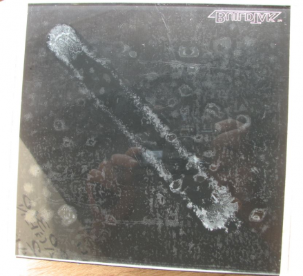
I am considering trying "BuildTak" which should allow me to use fully automatic Z homing, but I understand that it is a bit delicate.
Dave
I am considering trying "BuildTak" which should allow me to use fully automatic Z homing, but I understand that it is a bit delicate.
Dave
|
Re: Mounting dc42's Mini height sensor board May 10, 2016 08:09AM |
Registered: 10 years ago Posts: 14,672 |
Quote
dmould
The problem I have with all the IR based height sensors is due to the fact that I use an ABS/acetone solution to coat my build plate. All sensors trigger at a height that varies depending on the thickness and surface texture that I manage to achieve with the coating, and while DC42's sensor is better than any other, the variation is still >0.1mm, especially when the ABS slurry has been applied when the bed is hot (so it gets a frosted appearance).
Dave, have you tried either putting black paper between the glass and the heat spreader, or painting the top of the heat spreader or the back of the glass matt black? That may reduce the sensitivity to the coating.
Large delta printer [miscsolutions.wordpress.com], E3D tool changer, Robotdigg SCARA printer, Crane Quad and Ormerod
Disclosure: I design Duet electronics and work on RepRapFirmware, [duet3d.com].
|
Re: Mounting dc42's Mini height sensor board May 10, 2016 09:18AM |
Registered: 9 years ago Posts: 1,699 |
The sensor works well with BuildTak, but it's not very durable. Once the height is a little bit too deep the surface gets permanently damaged. Even though I took care my last BuildTak got damaged when printing PETG.
Next step will be that I will try Pertinax and soon I will try FilaPrint.
Slicer: Simplify3D 4.0; sometimes CraftWare 1.14 or Cura 2.7
Delta with Duet-WiFi, FW: 1.20.1RC2; mini-sensor board by dc42 for auto-leveling
Ormerod common modifications: Mini-sensor board by dc42, aluminum X-arm, 0.4 mm nozzle E3D like, 2nd fan, Z stepper nut M5 x 15, Herringbone gears, Z-axis bearing at top, spring loaded extruder with pneumatic fitting, Y belt axis tensioner
Ormerod 2: FW: 1.19-dc42 on Duet-WiFi. own build, modifications: GT2-belts, silicone heat-bed, different motors and so on. Printed parts: bed support, (PSU holder) and Y-feet.
Ormerod 1: FW: 1.15c-dc42 on 1k Duet-Board. Modifications: Aluminium bed-support, (nearly) all parts reprinted in PLA/ ABS, and so on.
|
Re: Mounting dc42's Mini height sensor board May 10, 2016 09:51AM |
Registered: 10 years ago Posts: 1,230 |
Quote
dmould
I am considering trying "BuildTak" which should allow me to use fully automatic Z homing, but I understand that it is a bit delicate.
I don't find it delicate (used a hammer and chisel to remove print) at all but the glue will fail and you will end up with an uneven surface impossible to zero on - here a picture from the glass side, white spots is air bubbles
Erik
|
Re: Mounting dc42's Mini height sensor board May 10, 2016 02:09PM |
Registered: 9 years ago Posts: 1,699 |
Erik in that case your first layer was too deep. BuildTak needs a complete different handling, but for me it didn't last long. I already killed three pieces within a week each.
Slicer: Simplify3D 4.0; sometimes CraftWare 1.14 or Cura 2.7
Delta with Duet-WiFi, FW: 1.20.1RC2; mini-sensor board by dc42 for auto-leveling
Ormerod common modifications: Mini-sensor board by dc42, aluminum X-arm, 0.4 mm nozzle E3D like, 2nd fan, Z stepper nut M5 x 15, Herringbone gears, Z-axis bearing at top, spring loaded extruder with pneumatic fitting, Y belt axis tensioner
Ormerod 2: FW: 1.19-dc42 on Duet-WiFi. own build, modifications: GT2-belts, silicone heat-bed, different motors and so on. Printed parts: bed support, (PSU holder) and Y-feet.
Ormerod 1: FW: 1.15c-dc42 on 1k Duet-Board. Modifications: Aluminium bed-support, (nearly) all parts reprinted in PLA/ ABS, and so on.
|
Re: Mounting dc42's Mini height sensor board May 11, 2016 07:16AM |
Registered: 10 years ago Posts: 2,472 |
Quote
dc42
Quote
dmould
The problem I have with all the IR based height sensors is due to the fact that I use an ABS/acetone solution to coat my build plate. All sensors trigger at a height that varies depending on the thickness and surface texture that I manage to achieve with the coating, and while DC42's sensor is better than any other, the variation is still >0.1mm, especially when the ABS slurry has been applied when the bed is hot (so it gets a frosted appearance).
Dave, have you tried either putting black paper between the glass and the heat spreader, or painting the top of the heat spreader or the back of the glass matt black? That may reduce the sensitivity to the coating.
I usually print on a thick (5mm) aluminium plate, which I am aware will be inaccurate due to being too reflective, but when I print on glass it sits directly on the red heater PCB with no heat spreader, and I still get the same issue. I may try spraying the aluminium plate with high-temperature matt black paint (as is sold to paint engine exhausts). You never know, that may prove suitable to print on directly. Not sure if that paint bonds directly to aluminium - probably not in which case it will need a light undercoat of zinc chromate which I'm pretty sure will survive bed temperatures.
OTOH as said, manually setting Z height is quick & easy and it's done while I'm at the printer setting up the print anyway, so as it won't improve print quality and is not a significant inconvenience I have no big motivation. It would be nice not to have to coat the plate though, which can be a bit of a PITA, and leaves visible brush marks on the base of the print, so I'm keen to experiment with surfaces that might eliminate that need. From other's comments it looks like Build-Tak may require replacement too often to be satisfactory.
Dave
|
Re: Mounting dc42's Mini height sensor board May 11, 2016 07:28AM |
Registered: 9 years ago Posts: 638 |
Quote
dmould
Quote
dc42
Quote
dmould
The problem I have with all the IR based height sensors is due to the fact that I use an ABS/acetone solution to coat my build plate. All sensors trigger at a height that varies depending on the thickness and surface texture that I manage to achieve with the coating, and while DC42's sensor is better than any other, the variation is still >0.1mm, especially when the ABS slurry has been applied when the bed is hot (so it gets a frosted appearance).
Dave, have you tried either putting black paper between the glass and the heat spreader, or painting the top of the heat spreader or the back of the glass matt black? That may reduce the sensitivity to the coating.
I usually print on a thick (5mm) aluminium plate, which I am aware will be inaccurate due to being too reflective, but when I print on glass it sits directly on the red heater PCB with no heat spreader, and I still get the same issue. I may try spraying the aluminium plate with high-temperature matt black paint (as is sold to paint engine exhausts). You never know, that may prove suitable to print on directly. Not sure if that paint bonds directly to aluminium - probably not in which case it will need a light undercoat of zinc chromate which I'm pretty sure will survive bed temperatures.
OTOH as said, manually setting Z height is quick & easy and it's done while I'm at the printer setting up the print anyway, so as it won't improve print quality and is not a significant inconvenience I have no big motivation. It would be nice not to have to coat the plate though, which can be a bit of a PITA, and leaves visible brush marks on the base of the print, so I'm keen to experiment with surfaces that might eliminate that need. From other's comments it looks like Build-Tak may require replacement too often to be satisfactory.
Dave
You can print a paper in black(or buy black paper) and put it between heat spreader and glass and it will work fine.
|
Re: Mounting dc42's Mini height sensor board May 11, 2016 12:18PM |
Registered: 10 years ago Posts: 2,472 |
Quote
Darathy
You can print a paper in black(or buy black paper) and put it between heat spreader and glass and it will work fine.
As said, I don't usually use glass, most of the time I print on a thick machined aluminium plate. Aluminium won't break if dropped or if a lot of force needs to be used to get the part off the plate.
When I do use glass, the ABS slurry I coat it with can vary between being completely transparent, and being translucent white like snow (mainly depends whether I coat hot or cold). This appears to affect the trigger height a little, though I have not tried using anything black under the glass.
Dave
|
Re: Mounting dc42's Mini height sensor board May 11, 2016 01:14PM |
Registered: 9 years ago Posts: 638 |
|
Re: Mounting dc42's Mini height sensor board May 11, 2016 01:46PM |
Registered: 10 years ago Posts: 1,230 |
Quote
Treito
Erik in that case your first layer was too deep. BuildTak needs a complete different handling, but for me it didn't last long. I already killed three pieces within a week each.
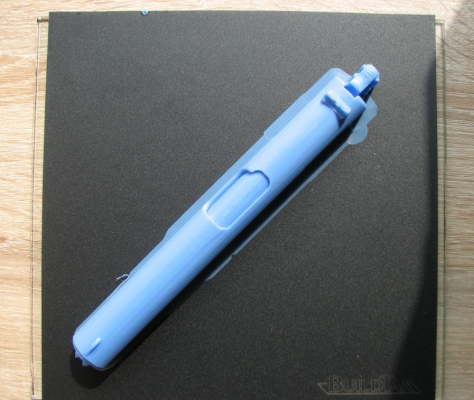
With a higher first layer the BuildTak would let go of the model and I would end up with a banana anyway, here a picture from the top of the model that pulled the BuildTak of the glass:
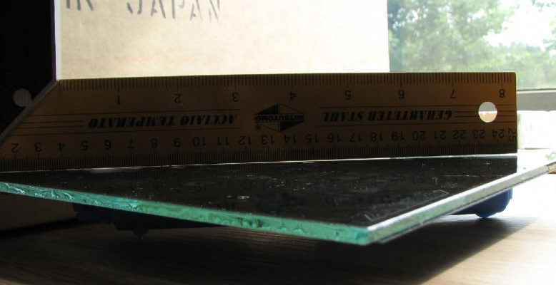
..and from the under side of the glass, notice how much the print (ABS, still sitting on the BuildTak) is bending 4mm glass:
..and I needed those parts straight as a whistle so no lines would show when glued together:
Erik
|
Re: Mounting dc42's Mini height sensor board May 12, 2016 07:19AM |
Registered: 10 years ago Posts: 2,472 |
Quote
Darathy
what abaut anodized aluminum? does it still reflect as much?
Black anodizing would probably behave very similar to using the glass - I suspect the differences in the ABS slurry would still have a small effect. I did consider getting it anodized but decided to use paint instead because (1) there is an outside chance that the first layer will stick to the paint without needing to be coated and (2) I sometimes scratch the plate when removing difficult parts, and these can easily be touched up with paint, but would be permanent marks with anodizing. Also anodizing is not cheap unless I can arrange for it to be done as part of a bigger batch of parts, (though I could probably get it done cheaper if I shop around).
Dave
|
Re: Mounting dc42's Mini height sensor board May 12, 2016 09:48AM |
Registered: 10 years ago Posts: 14,672 |
Quote
dmould
Quote
Darathy
what abaut anodized aluminum? does it still reflect as much?
Black anodizing would probably behave very similar to using the glass - I suspect the differences in the ABS slurry would still have a small effect. I did consider getting it anodized but decided to use paint instead because (1) there is an outside chance that the first layer will stick to the paint without needing to be coated and (2) I sometimes scratch the plate when removing difficult parts, and these can easily be touched up with paint, but would be permanent marks with anodizing. Also anodizing is not cheap unless I can arrange for it to be done as part of a bigger batch of parts, (though I could probably get it done cheaper if I shop around).
Dave
The problem with glass is that the reflection from the underside interferes slightly with the reflection from the top surface. Adding a thick coat of ABS slurry or whatever increases the reflectivity of the top surface and attenuates the reflection from the bottom surface, which is why it slightly affects the trigger height.
If you anodize the aluminium (although I suggest not matt black because that may reflect too little IR to work without any coating) and use it without glass, I would expect ABS slurry to have negligible effect on the trigger height.
I recommend that when using glass on top of aluminium, the aluminium be painted matt black to reduce the reflection from under the glass - or use a piece of black paper between the two. However, there will still be a small reflection from the back surface of the glass in those areas where there is a gap between the glass and the aluminium of more than about half a micron. So I think an even better solution may be to paint the back of the glass matt black, if the paint will stick - I haven't tried it yet.
Edited 4 time(s). Last edit at 05/12/2016 09:51AM by dc42.
Large delta printer [miscsolutions.wordpress.com], E3D tool changer, Robotdigg SCARA printer, Crane Quad and Ormerod
Disclosure: I design Duet electronics and work on RepRapFirmware, [duet3d.com].
|
Re: Mounting dc42's Mini height sensor board May 14, 2016 09:11AM |
Registered: 9 years ago Posts: 245 |
Quote
Treito
The sensor works well with BuildTak, but it's not very durable. Once the height is a little bit too deep the surface gets permanently damaged. Even though I took care my last BuildTak got damaged when printing PETG.
Next step will be that I will try Pertinax and soon I will try FilaPrint.
Treito
Dont forget to exhaust the printer.
Pertinax is toxic. You'll have to sand it every X prints, wich is messy and the dust is also harmful !
Onlinestore: www.filafarm.com & Galerie
Sorry, only registered users may post in this forum.
