Mounting dc42's Mini height sensor board
Posted by Treito
|
Re: Mounting dc42's Mini height sensor board May 14, 2016 03:12PM |
Registered: 9 years ago Posts: 1,699 |
As long as you keep the temperature below 120°C there should not be any toxic fumes.
The most interesting thing is the comparison between BuildTak and Pertinax.
I am not sure if a better adhesion for ABS is possible. If the Pertinax plate is better then I will buy a FilaPrint. If not I would stay with PrintBite.
Slicer: Simplify3D 4.0; sometimes CraftWare 1.14 or Cura 2.7
Delta with Duet-WiFi, FW: 1.20.1RC2; mini-sensor board by dc42 for auto-leveling
Ormerod common modifications: Mini-sensor board by dc42, aluminum X-arm, 0.4 mm nozzle E3D like, 2nd fan, Z stepper nut M5 x 15, Herringbone gears, Z-axis bearing at top, spring loaded extruder with pneumatic fitting, Y belt axis tensioner
Ormerod 2: FW: 1.19-dc42 on Duet-WiFi. own build, modifications: GT2-belts, silicone heat-bed, different motors and so on. Printed parts: bed support, (PSU holder) and Y-feet.
Ormerod 1: FW: 1.15c-dc42 on 1k Duet-Board. Modifications: Aluminium bed-support, (nearly) all parts reprinted in PLA/ ABS, and so on.
|
Re: Mounting dc42's Mini height sensor board May 17, 2016 04:25AM |
Registered: 9 years ago Posts: 15 |
I've also made a design to mount the mini IR Sensor.
Please see:
[www.thingiverse.com]
I've found that even with the Original Ormerod and Ormerod 2, the X homing tab works a lot better with some Tipex on it. I have been working in rooms with High Ambient Light, so I often found my printer would not home as there wasn't enough of a difference on the Modulated one. I have finally upgraded to DC42's Mini Height Sensor as I wish to do away with the White paper on the corners of the bed.
Edited 4 time(s). Last edit at 05/17/2016 07:32AM by Mitch.
|
Re: Mounting dc42's Mini height sensor board May 17, 2016 06:50AM |
Registered: 9 years ago Posts: 1,699 |
The mounting holes were according to the switch and the holes are 9.5mm (? I cannot check at the moment) away according to the data sheet.
I printed two versions of them (one is not published yet) and I had no problems using the holes. My holes have a tight fit.
Maybe you have another version of the x-carriage. Which printer version do you own? Which x-carriage do you use? Did you scale the x-carriage?
Using OpenSCAD would have been the recommended way to change the mounting part and I guess this is directly supported by thingiverse. This is only for the sensor pad.
Edited 1 time(s). Last edit at 05/17/2016 06:51AM by Treito.
Slicer: Simplify3D 4.0; sometimes CraftWare 1.14 or Cura 2.7
Delta with Duet-WiFi, FW: 1.20.1RC2; mini-sensor board by dc42 for auto-leveling
Ormerod common modifications: Mini-sensor board by dc42, aluminum X-arm, 0.4 mm nozzle E3D like, 2nd fan, Z stepper nut M5 x 15, Herringbone gears, Z-axis bearing at top, spring loaded extruder with pneumatic fitting, Y belt axis tensioner
Ormerod 2: FW: 1.19-dc42 on Duet-WiFi. own build, modifications: GT2-belts, silicone heat-bed, different motors and so on. Printed parts: bed support, (PSU holder) and Y-feet.
Ormerod 1: FW: 1.15c-dc42 on 1k Duet-Board. Modifications: Aluminium bed-support, (nearly) all parts reprinted in PLA/ ABS, and so on.
I printed two versions of them (one is not published yet) and I had no problems using the holes. My holes have a tight fit.
Maybe you have another version of the x-carriage. Which printer version do you own? Which x-carriage do you use? Did you scale the x-carriage?
Edited 1 time(s). Last edit at 05/17/2016 06:51AM by Treito.
Slicer: Simplify3D 4.0; sometimes CraftWare 1.14 or Cura 2.7
Delta with Duet-WiFi, FW: 1.20.1RC2; mini-sensor board by dc42 for auto-leveling
Ormerod common modifications: Mini-sensor board by dc42, aluminum X-arm, 0.4 mm nozzle E3D like, 2nd fan, Z stepper nut M5 x 15, Herringbone gears, Z-axis bearing at top, spring loaded extruder with pneumatic fitting, Y belt axis tensioner
Ormerod 2: FW: 1.19-dc42 on Duet-WiFi. own build, modifications: GT2-belts, silicone heat-bed, different motors and so on. Printed parts: bed support, (PSU holder) and Y-feet.
Ormerod 1: FW: 1.15c-dc42 on 1k Duet-Board. Modifications: Aluminium bed-support, (nearly) all parts reprinted in PLA/ ABS, and so on.
|
Re: Mounting dc42's Mini height sensor board May 17, 2016 07:21AM |
Registered: 9 years ago Posts: 15 |
|
Re: Mounting dc42's Mini height sensor board October 22, 2016 06:17AM |
Registered: 8 years ago Posts: 57 |
I have just fitted the mini-height sensor board to my ormerod 1 using Treito's plastic parts (http://www.thingiverse.com/thing:1395051) made from white PLA.
The electronics appears to be working fine. - The LED on the board flashes four times when I switch on (connecting the USB cable), Monitoring the Z probe on the web interface I get a reading of zero when far away from any reflecting surface, if I place a sheet of white paper a few millimetres from the sensor I get a reading of 463, which rises to 533 when I move it closer. All this seems to agree with the documentation.
If I move the X axis towards zero the sensor sees the sensor pad, the LEd illuminates an I get a reading of 533 on the Z probe. At this pont the board is about 10mm from the Z leadscrew, and can be moved a further 5mm before coming to the mechanical endstop. Even at this point the board is well away from any metal work.
However, if I send the Home X command from the web interface it moves to X0, the LED illuminates but the carriage continues to move an bang against the endstop until I do an emergency stop.
Do I need to make any changes to the firmware to tell it that a reading of 533 signifies that it has reached X=0? or is there anything else wrong?
|
Re: Mounting dc42's Mini height sensor board October 22, 2016 07:27AM |
Registered: 10 years ago Posts: 14,672 |
Quote
PeterSimpson
I have just fitted the mini-height sensor board to my ormerod 1 using Treito's plastic parts (http://www.thingiverse.com/thing:1395051) made from white PLA.
The electronics appears to be working fine. - The LED on the board flashes four times when I switch on (connecting the USB cable), Monitoring the Z probe on the web interface I get a reading of zero when far away from any reflecting surface, if I place a sheet of white paper a few millimetres from the sensor I get a reading of 463, which rises to 533 when I move it closer. All this seems to agree with the documentation.
If I move the X axis towards zero the sensor sees the sensor pad, the LEd illuminates an I get a reading of 533 on the Z probe. At this pont the board is about 10mm from the Z leadscrew, and can be moved a further 5mm before coming to the mechanical endstop. Even at this point the board is well away from any metal work.
However, if I send the Home X command from the web interface it moves to X0, the LED illuminates but the carriage continues to move an bang against the endstop until I do an emergency stop.
Do I need to make any changes to the firmware to tell it that a reading of 533 signifies that it has reached X=0? or is there anything else wrong?
1. Make sure you have the probe type set to 1 (P1 parameter) in your M558 command in config.g.
2. Make sure you have the P parameter in your G31 command in config.g set to 500.
3. Check your homing files for additional M558 and G31 commands, and remove any that you find.
Large delta printer [miscsolutions.wordpress.com], E3D tool changer, Robotdigg SCARA printer, Crane Quad and Ormerod
Disclosure: I design Duet electronics and work on RepRapFirmware, [duet3d.com].
|
Re: Mounting dc42's Mini height sensor board October 22, 2016 04:54PM |
Registered: 8 years ago Posts: 57 |
|
Re: Mounting dc42's Mini height sensor board November 09, 2016 10:54AM |
Registered: 8 years ago Posts: 57 |
I have just fitted the mini height sensor and am about to set up the a z home position.
Could you please clarify something for me first.
On the installation instructions on [miscsolutions.wordpress.com] is the instruction:
To calibrate the sensor for Z homing and bed probing, home X and Y, then position the head over the centre of the bed. With the nozzle at operating temperature, lower the head so that it is just touching the bed or just gripping a sheet of paper, then send G92 Z0 to define that position as Z=0. Raise the head 5mm and remove the paper. Then send command G30 S-1 to probe the bed at that point without adjusting the Z height setting. Read off the Z height in the “Head Position” box in Duet Web Control, or from the Z coordinate shown on the Control page of PanelDue, or send M114 to retrieve the head position if using a USB host program on a PC. It should be in the range 0.5 to 2.5mm. Use that value for the Z parameter in your G31 command in config.g.
I think there must be a printing error here!
Should you nt be saying "raise the head until you get a reading of ??? for the Z-probe"? If so, what is ??? Is it one of the two values - 465? 535? or is it the transition from one to the other?
|
Re: Mounting dc42's Mini height sensor board November 09, 2016 02:08PM |
Registered: 10 years ago Posts: 14,672 |
The text is correct, no printing error.
Large delta printer [miscsolutions.wordpress.com], E3D tool changer, Robotdigg SCARA printer, Crane Quad and Ormerod
Disclosure: I design Duet electronics and work on RepRapFirmware, [duet3d.com].
Large delta printer [miscsolutions.wordpress.com], E3D tool changer, Robotdigg SCARA printer, Crane Quad and Ormerod
Disclosure: I design Duet electronics and work on RepRapFirmware, [duet3d.com].
|
Re: Mounting dc42's Mini height sensor board November 10, 2016 06:42PM |
Registered: 8 years ago Posts: 57 |
Am I thick, or is there an instruction missing from the paragraph I quoted above which was in the setting up instructions for the duet board?Quote
dc42
The text is correct, no printing error.
Below is the same paragraph repeated with the stages numbered and my comments against each:
To calibrate the sensor for Z homing and bed probing,
1. home X and Y, then position the head over the centre of the bed. OK!
2. With the nozzle at operating temperature, lower the head so that it is just touching the bed or just gripping a sheet of paper, OK!
3. then send G92 Z0 to define that position as Z=0. The web interface will show Z=0
4. Raise the head 5mm and remove the paper. The web interface will show Z=5.0
5. Then send command G30 S-1 to probe the bed at that point without adjusting the Z height setting. The Z probe value could be anything -probably zero as it is 5mm from the bed
6. Read off the Z height in the “Head Position” box in Duet Web Control, or from the Z coordinate shown on the Control page of PanelDue, or send M114 to retrieve the head position if using a USB host program on a PC. It should be in the range 0.5 to 2.5mm. No! it will read 5.0mm because you haven't moved it since you raised it 5mm from the z=0 position
7. Use that value for the Z parameter in your G31 command in config.g. From the above that would be G31 Z5.0 P0!
In the section on 'setting up with other electronics' you have a sequence of instructions to move the height in 0.05mm or smaller steps whilst watching the LED. Should these instructions or something similar be included in the setting up for the Duet board? Maybe going from the Z probe values rather than the LED?
|
Re: Mounting dc42's Mini height sensor board November 11, 2016 04:29AM |
Registered: 9 years ago Posts: 1,159 |
in step 5 the G30 s-1 will move the head down until the probe triggers this is the Z Height you need to read from either the PanelDUE or the Web interface.
Edit for Typo
In step 7 it would be G31 Zx.xx P500 where x.xx is the value read after you have issued the G30 S-1 in step 5.
Edited 2 time(s). Last edit at 11/11/2016 04:31AM by dougal1957.
Edit for Typo
In step 7 it would be G31 Zx.xx P500 where x.xx is the value read after you have issued the G30 S-1 in step 5.
Edited 2 time(s). Last edit at 11/11/2016 04:31AM by dougal1957.
|
Re: Mounting dc42's Mini height sensor board November 11, 2016 09:26AM |
Registered: 8 years ago Posts: 57 |
Thank you very much for the clarification. It appears that the answer to my very first question is 'yes"!!!
All this is of academic interest at present, because I have just discovered that in using the recommended parts for mounting the circuit board, the bottom edge of the circuit board is 5mm above the bottom edge of the printed 'x carriage' part which means that I can't take the sensor any lower than 5mm above the bed before tha x carriage crashes into the bed.
It looks as though I will either have to either cut 5mm or more of the carriage, or design and have printed a new sensor mount and sensor pad such that the board will be 5mm or more below where it is now.
|
Re: Mounting dc42's Mini height sensor board November 11, 2016 09:29AM |
Registered: 9 years ago Posts: 1,159 |
Quote
PeterSimpson
Thank you very much for the clarification. It appears that the answer to my very first question is 'yes"!!!
All this is of academic interest at present, because I have just discovered that in using the recommended parts for mounting the circuit board, the bottom edge of the circuit board is 5mm above the bottom edge of the printed 'x carriage' part which means that I can't take the sensor any lower than 5mm above the bed before tha x carriage crashes into the bed.
It looks as though I will either have to either cut 5mm or more of the carriage, or design and have printed a new sensor mount and sensor pad such that the board will be 5mm or more below where it is now.
It needs to be arround 2-2.5 mm above the bed when the Nozzle is just touching the Bed?
|
Re: Mounting dc42's Mini height sensor board November 11, 2016 11:42AM |
Registered: 10 years ago Posts: 14,672 |
Quote
dougal1957
Quote
PeterSimpson
Thank you very much for the clarification. It appears that the answer to my very first question is 'yes"!!!
All this is of academic interest at present, because I have just discovered that in using the recommended parts for mounting the circuit board, the bottom edge of the circuit board is 5mm above the bottom edge of the printed 'x carriage' part which means that I can't take the sensor any lower than 5mm above the bed before tha x carriage crashes into the bed.
It looks as though I will either have to either cut 5mm or more of the carriage, or design and have printed a new sensor mount and sensor pad such that the board will be 5mm or more below where it is now.
It needs to be arround 2-2.5 mm above the bed when the Nozzle is just touching the Bed?
I recommend aiming for 1.5mm. Below 1mm there is a risk of the sensor contacting blobs or curl-up on the print, and above 2mm there is a risk that the sensor will not trigger.
Large delta printer [miscsolutions.wordpress.com], E3D tool changer, Robotdigg SCARA printer, Crane Quad and Ormerod
Disclosure: I design Duet electronics and work on RepRapFirmware, [duet3d.com].
|
Re: Mounting dc42's Mini height sensor board November 12, 2016 06:07PM |
Registered: 7 years ago Posts: 34 |
I have one of these, from Filastruder, and like it very much. I'm curious - is the height of "make" on the diffIR a function of just beam aim from the LEDs, or is intensity wrapped up in that too?Quote
dc42
I recommend aiming for 1.5mm. Below 1mm there is a risk of the sensor contacting blobs or curl-up on the print, and above 2mm there is a risk that the sensor will not trigger.
|
Re: Mounting dc42's Mini height sensor board November 12, 2016 06:14PM |
Registered: 10 years ago Posts: 14,672 |
It's beam aim from the LEDs. I have experimented with scaling the expected intensities to calibrate the trigger height, however I prefer not to do this because the phototransistor response is not entirely linear.
Large delta printer [miscsolutions.wordpress.com], E3D tool changer, Robotdigg SCARA printer, Crane Quad and Ormerod
Disclosure: I design Duet electronics and work on RepRapFirmware, [duet3d.com].
Large delta printer [miscsolutions.wordpress.com], E3D tool changer, Robotdigg SCARA printer, Crane Quad and Ormerod
Disclosure: I design Duet electronics and work on RepRapFirmware, [duet3d.com].
|
Re: Mounting dc42's Mini height sensor board November 13, 2016 08:38AM |
Registered: 10 years ago Posts: 1,230 |
Quote
dc42
I recommend aiming for 1.5mm. Below 1mm there is a risk of the sensor contacting blobs or curl-up on the print, and above 2mm there is a risk that the sensor will not trigger.
Good advice on playing it safe, just want to note that 2,5mm never failed on my two machines, both with 4mm glass directly on the PCB heater, even think I could raise that a bit with mat black under the glass but should not be needed
What a difference your Sensor made, thank you!
Erik
|
Re: Mounting dc42's Mini height sensor board December 28, 2016 02:04PM |
Registered: 8 years ago Posts: 57 |
Having been out of operation for a month or so I am back to setting up my Ormerod 1.
In homing the X axis I notice that with the mini height sensor and Treito's plastic parts that the X=0 position is now further onto the bed than before. a distance of about 10mm I think.
Looking at the Home-x.g file I see that the head is moved in a negative direction until it reaches the end stop then moves the head by +15mm which is then set to X=0.
Can anyone tell me whether this 15mm movement is required? Could I reduce the distance to say 5mm (enough to clear the sensor)? This would, I think bring the useable bed area back to what it was with the oud sensor?
FYI here is the original code for home-x.g with a comment against the line I propose to change:
G91 ; set movement to relative mode
G1 Z5 F200 ; move Z up 5mm
G90 ; set movement to absolute mode
;M558 P1 ; UNCOMMENT this line if you upgrade to a 4-wire probe
G1 X-240 F2000 S1 ; home X
G92 X0 ; set position to X=0
G1 X3 F200 ; move axis away from X=0
G1 X-5 F200 S1 ; home again, slower
G92 X0 ; set position to X=0
G1 X15 F2000 ; ADJUST the X value to put the nozzle on the edge of the bed **** Change this line to G1 X5 F2000 ***
G92 X0 ; set position to X=0
;M558 P2 ; UNCOMMENT this line if you upgrade to a 4-wire probe
G91 ; set movement to relative mode
G1 Z-5 F200 ; move Z down 5mm
G90 ; set movement to absolute mode
Edited 1 time(s). Last edit at 12/28/2016 02:08PM by PeterSimpson.
|
Re: Mounting dc42's Mini height sensor board December 28, 2016 04:52PM |
Registered: 10 years ago Posts: 14,672 |
Using G92 to adjust the homing position is the old way. The modern way is to define the axis limits in the M208 commands. See [duet3d.com], in particular the bit about the M208 commands and the homing files.
Whichever way you do it, you should set it up so that X=0 is at the edge of the bed.
Large delta printer [miscsolutions.wordpress.com], E3D tool changer, Robotdigg SCARA printer, Crane Quad and Ormerod
Disclosure: I design Duet electronics and work on RepRapFirmware, [duet3d.com].
Whichever way you do it, you should set it up so that X=0 is at the edge of the bed.
Large delta printer [miscsolutions.wordpress.com], E3D tool changer, Robotdigg SCARA printer, Crane Quad and Ormerod
Disclosure: I design Duet electronics and work on RepRapFirmware, [duet3d.com].
|
Re: Mounting dc42's Mini height sensor board March 10, 2017 08:23PM |
Registered: 7 years ago Posts: 4 |
Just wanted to say how pleased I am with your height sensor.
No other sensor was compact enough to easily mount anywhere near the hot-end with my fan duct in place.
Also, I like printing on glass.
To measure the standard deviation of the height measurements from the sensor, I tweaked Marlin so that G30 would output the trigger height to 3 decimal places (1 micron resolution). I turned on my printer and made 46 measurements with G30 and got an s.d. of 1.4 microns. I noticed a trend in the data, presumably due to temperature drift somewhere in the system (probably the steppers warming up my crappy M5 threaded rods so the trigger point appeared to get lower with time). So I did another 34 measurements and the s.d. was 0.8 microns, but still with a small trend, so the device is way more accurate than I was expecting.
I used a permanent marker pen to blacken the red heated bed pcb under the probe areas, and 3 mm glass which had a thin layer of UHU glue stick on it, as I would normally use for a print.
The only (minor) issue I had was that initially I mounted the sensor so that the bottom of the board was 1.5 mm above the tip of the nozzle, as recommended. The problem was this meant I reduced my build area from 200x200 to 200x185, to avoid the board colliding with the bulldog clips holding the glass down.
I commonly use the full 200x200, so this was a problem.
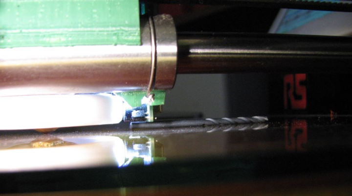
I am not sure how other people deal with this, but I used my hot-air rework station to tweak the angle of the outer led to increase the trigger height by ~0.5 mm out to 3.3 mm. This meant I could mount the board so it would clear the clips (which rise 2.65 mm above the glass), and still leave the nozzle tip 0.4 mm above the bed when the sensor triggers.
It seems to me that scaling the spacing of the optical components a little (x 1.3 say) to achieve a slightly greater trigger height would be beneficial if/when you do v1.3. There is a little spare room still on the current 24 mm wide board to do this, but I think it would be worth it even if the board had to be a bit wider, since I don't think the width would be a constraint for most installations.
Thanks again for a great sensor,
Kit
Edited 1 time(s). Last edit at 03/10/2017 08:28PM by spinorkit.
|
Re: Mounting dc42's Mini height sensor board March 11, 2017 02:24AM |
Registered: 10 years ago Posts: 14,672 |
I'm glad you like the sensor!
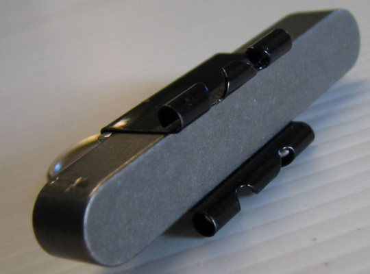
Ormerod users mostly use Swiss clips (= frameless photo mount clips) instead of bulldog clips to hold the glass down. The ones on my Ormerod protrude about 1mm above the glass.
Large delta printer [miscsolutions.wordpress.com], E3D tool changer, Robotdigg SCARA printer, Crane Quad and Ormerod
Disclosure: I design Duet electronics and work on RepRapFirmware, [duet3d.com].
|
Re: Mounting dc42's Mini height sensor board March 11, 2017 04:19AM |
Registered: 7 years ago Posts: 4 |
Thanks for the photos.
Actually, I bought some swiss clips from E3D in the hope they would solve this issue. The pieces of circuit board (which I assume you made yourself) look like they would make them easier to use.
The problem is that when I started printing my glider wings (Proteus slope soarer) I noticed problems with the glass bending due to the tension in the print. I discovered this was even more of a problem with wings from [3dlabprint.com] since any warping makes it impossible to glue the wings together properly. Their Spitfire wing root would bend even 4 mm thick glass by more than 1mm (leaving a 2 mm gap when joining)!
To fix this I bolted a 16x16mm aluminium channel extrusion diagonally under my heated bed and I use lots of medium size bulldog clips to hold the corners of the glass down. This gives me one warp-free diagonal.
The extrusion means I can't get swiss clips anywhere near the corners.
Thanks again,
Kit
|
Re: Mounting dc42's Mini height sensor board March 11, 2017 06:41AM |
Registered: 10 years ago Posts: 14,672 |
Use thicker glass?
Large delta printer [miscsolutions.wordpress.com], E3D tool changer, Robotdigg SCARA printer, Crane Quad and Ormerod
Disclosure: I design Duet electronics and work on RepRapFirmware, [duet3d.com].
Large delta printer [miscsolutions.wordpress.com], E3D tool changer, Robotdigg SCARA printer, Crane Quad and Ormerod
Disclosure: I design Duet electronics and work on RepRapFirmware, [duet3d.com].
|
Re: Mounting dc42's Mini height sensor board March 11, 2017 07:01AM |
Registered: 7 years ago Posts: 4 |
Yes, it starts getting quite heavy though. One mm of glass weighs about twice as much as the aluminium extrusion I put in, and I find it difficult cutting the corners off 4 mm glass let alone 5 mm.
Also, I find thicker glass more prone to cracking due to the heated bed, unless you go for expensive borosilicate, I guess.
Anyway, tweaking the outer led worked well and hasn't compromised the accuracy.
Regards,
Kit
Also, I find thicker glass more prone to cracking due to the heated bed, unless you go for expensive borosilicate, I guess.
Anyway, tweaking the outer led worked well and hasn't compromised the accuracy.
Regards,
Kit
|
Re: Mounting dc42's Mini height sensor board March 11, 2017 10:59AM |
Registered: 10 years ago Posts: 1,230 |
Quote
spinorkit
To fix this I bolted a 16x16mm aluminium channel extrusion diagonally under my heated bed and I use lots of medium size bulldog clips to hold the corners of the glass down. This gives me one warp-free diagonal.
The extrusion means I can't get swiss clips anywhere near the corners.
Thanks again,
Kit
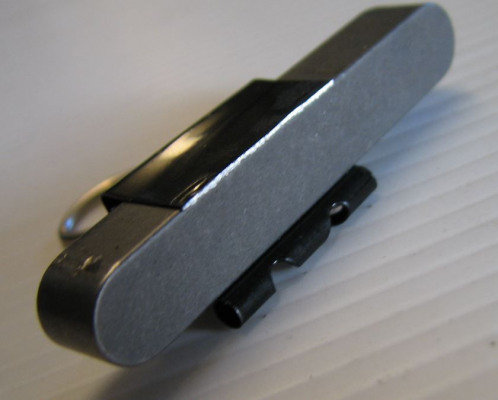
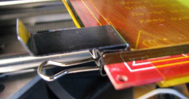
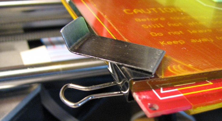
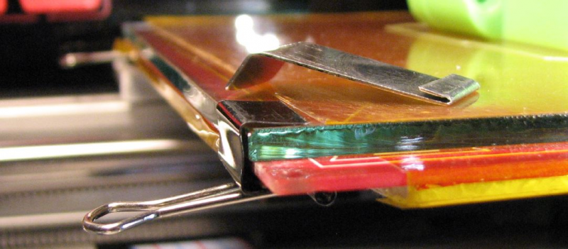
I modified the bulldog clips, cut one side, rounded the edges so not to damage the kapton and made a simple tool for mounting the clips
Erik
|
Re: Mounting dc42's Mini height sensor board March 11, 2017 03:48PM |
Registered: 7 years ago Posts: 4 |
Sorry, only registered users may post in this forum.
