Ormerod 3
Posted by Treito
Hello,
I am considering to design a new version of an Ormerod, but how is the interest?
What change would be important and what details should I keep?
Best regards,
Sven
Slicer: Simplify3D 4.0; sometimes CraftWare 1.14 or Cura 2.7
Delta with Duet-WiFi, FW: 1.20.1RC2; mini-sensor board by dc42 for auto-leveling
Ormerod common modifications: Mini-sensor board by dc42, aluminum X-arm, 0.4 mm nozzle E3D like, 2nd fan, Z stepper nut M5 x 15, Herringbone gears, Z-axis bearing at top, spring loaded extruder with pneumatic fitting, Y belt axis tensioner
Ormerod 2: FW: 1.19-dc42 on Duet-WiFi. own build, modifications: GT2-belts, silicone heat-bed, different motors and so on. Printed parts: bed support, (PSU holder) and Y-feet.
Ormerod 1: FW: 1.15c-dc42 on 1k Duet-Board. Modifications: Aluminium bed-support, (nearly) all parts reprinted in PLA/ ABS, and so on.
|
Re: Ormerod 3 September 19, 2017 12:08PM |
Registered: 10 years ago Posts: 112 |
|
Re: Ormerod 3 September 19, 2017 01:51PM |
Registered: 9 years ago Posts: 1,699 |
The idea would be to support the arm at the front with keeping the shape as far as possible.
A more stable frame reducing the problem of twisted rods and so on.
I am wondering if this would worth the amount of work or if I should simply construct a simply design which will not have much in common with the Ormerod.
Besides you could put the printer into a closet.
Slicer: Simplify3D 4.0; sometimes CraftWare 1.14 or Cura 2.7
Delta with Duet-WiFi, FW: 1.20.1RC2; mini-sensor board by dc42 for auto-leveling
Ormerod common modifications: Mini-sensor board by dc42, aluminum X-arm, 0.4 mm nozzle E3D like, 2nd fan, Z stepper nut M5 x 15, Herringbone gears, Z-axis bearing at top, spring loaded extruder with pneumatic fitting, Y belt axis tensioner
Ormerod 2: FW: 1.19-dc42 on Duet-WiFi. own build, modifications: GT2-belts, silicone heat-bed, different motors and so on. Printed parts: bed support, (PSU holder) and Y-feet.
Ormerod 1: FW: 1.15c-dc42 on 1k Duet-Board. Modifications: Aluminium bed-support, (nearly) all parts reprinted in PLA/ ABS, and so on.
|
Re: Ormerod 3 September 19, 2017 03:57PM |
Registered: 10 years ago Posts: 112 |
|
Re: Ormerod 3 September 25, 2017 06:58AM |
Registered: 8 years ago Posts: 42 |
Hello Treito, the Redblunt is right.
X arm ist not up to date, and must be fixet like in prusa i3, and it will be nice if Ormerod 3 will be mobile...unfortunately it is not possible to carry the Ormerod or transport it from a to b.
And that the bed on the y axis is, is also not good, it is much more precise when hieter moves in x and y axis, or not?
This one is a good form =>
[3dprint.com]
[www.3dfactories.de]
And Z lift like on Form 2.
[www.ebay.de]
I think of building a delta or normal printer in Box, like Profi3dmaker.
If you need help in solidworks, tell me...but I believe you can do it yourself =D
Edited 2 time(s). Last edit at 09/25/2017 08:54AM by bigbangnow.
|
Re: Ormerod 3 September 28, 2017 08:32AM |
Registered: 9 years ago Posts: 1,699 |
Hello,
I use Fusion 360
I think you did not get the question. If I would change the direction of the heated bed to the z-axis it would not be an Ormerod anymore. That is why I am asking. At the moment I try to finish a CoreXY, but my Ormerod 2 needs more attention than I thought.
Best regards,
Sven
Slicer: Simplify3D 4.0; sometimes CraftWare 1.14 or Cura 2.7
Delta with Duet-WiFi, FW: 1.20.1RC2; mini-sensor board by dc42 for auto-leveling
Ormerod common modifications: Mini-sensor board by dc42, aluminum X-arm, 0.4 mm nozzle E3D like, 2nd fan, Z stepper nut M5 x 15, Herringbone gears, Z-axis bearing at top, spring loaded extruder with pneumatic fitting, Y belt axis tensioner
Ormerod 2: FW: 1.19-dc42 on Duet-WiFi. own build, modifications: GT2-belts, silicone heat-bed, different motors and so on. Printed parts: bed support, (PSU holder) and Y-feet.
Ormerod 1: FW: 1.15c-dc42 on 1k Duet-Board. Modifications: Aluminium bed-support, (nearly) all parts reprinted in PLA/ ABS, and so on.
|
Re: Ormerod 3 October 08, 2017 10:21AM |
Registered: 6 years ago Posts: 174 |
Quote
bigbangnow
Hello Treito, the Redblunt is right.
X arm ist not up to date, and must be fixet like in prusa i3, and it will be nice if Ormerod 3 will be mobile...unfortunately it is not possible to carry the Ormerod or transport it from a to b.
=D
I carry mine around every day. It rises along in my car and prints during the day at work and evenings at my parents' home. And weekends at my own home.
Have a look at my post in "Any Ormerod owners in Cape Town."
I made some changes to the Ormerod 1 and incorporated a handle ontpop of the Z Extrusion. It is perfectly balanced.
Edited 1 time(s). Last edit at 10/08/2017 10:22AM by Karoo Klong.
|
Re: Ormerod 3 October 09, 2017 08:13AM |
Registered: 8 years ago Posts: 30 |
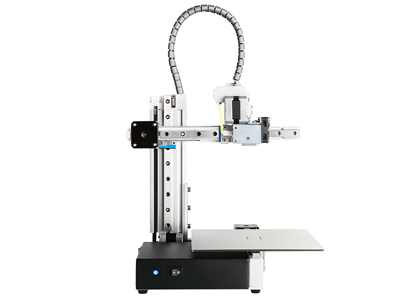
The best way to increase precision with the Ormerod design, imo, is to replace the smooth rods and linear bearings on all 3 axis with linear rails. As is done with the Cetus MKII.
|
Re: Ormerod 3 December 06, 2018 05:31AM |
Registered: 6 years ago Posts: 174 |
|
Re: Ormerod 3 December 06, 2018 08:16AM |
Registered: 10 years ago Posts: 466 |
This seems to have come to a halt, but what I am doing is upgrading my Z axis. I was never too happy with 2 gears on the Z motor, so Im going to print these parts and upgrade to a direct drive.
Ormerod 2 Direct Drive
Ormerod 2 Direct Drive
|
Re: Ormerod 3 December 06, 2018 08:31AM |
Registered: 6 years ago Posts: 174 |
|
Re: Ormerod 3 December 06, 2018 08:43AM |
Registered: 10 years ago Posts: 466 |
Here is Another Z axis upgrade , also a good one. The one in the last post was inspired by this one.
My issue here will be with the type of IR probe I have mounted, I am afraid I will loose about 2 cm of printing area because the IR probe trigger pad would have to stop the probe at the position that is on the photo.
Edited 1 time(s). Last edit at 12/06/2018 08:44AM by Sardi.
My issue here will be with the type of IR probe I have mounted, I am afraid I will loose about 2 cm of printing area because the IR probe trigger pad would have to stop the probe at the position that is on the photo.

Edited 1 time(s). Last edit at 12/06/2018 08:44AM by Sardi.
|
Re: Ormerod 3 December 06, 2018 09:13AM |
Registered: 6 years ago Posts: 174 |
|
Re: Ormerod 3 December 06, 2018 09:19AM |
Registered: 10 years ago Posts: 466 |
True, I have one laying around doing nothing.
But I wouldnt know if there is anything to change in the config.sys file for that setup to work, nor where would I plug in the new switch on the board. Right now the probe is acting as both an end switch and a height probe.
Edited 1 time(s). Last edit at 12/06/2018 09:23AM by Sardi.
But I wouldnt know if there is anything to change in the config.sys file for that setup to work, nor where would I plug in the new switch on the board. Right now the probe is acting as both an end switch and a height probe.
Edited 1 time(s). Last edit at 12/06/2018 09:23AM by Sardi.
|
Re: Ormerod 3 December 06, 2018 09:22AM |
Registered: 6 years ago Posts: 174 |
|
Re: Ormerod 3 December 07, 2018 05:37AM |
Registered: 10 years ago Posts: 466 |
|
Re: Ormerod 3 December 07, 2018 06:26AM |
Registered: 8 years ago Posts: 45 |
Quote
Sardi
I am having the hardest time finding the threaded rod 8*8, length max 400mm.... Anyone knows where I can order one of those?
EDIT: Or should I be looking out for 8*2 or something else?
For the Z axis I would always go with the lead screw built into the motor. Secure the motor well and leave the top end floating. My personal experience is that the couplers not only take up too much space but the common ones are too flexible. I used this one from Ooznest. [ooznest.co.uk]
Edited 1 time(s). Last edit at 12/07/2018 06:30AM by trevmas.
|
Re: Ormerod 3 December 07, 2018 06:28AM |
Registered: 8 years ago Posts: 45 |
|
Re: Ormerod 3 December 07, 2018 06:35AM |
Registered: 8 years ago Posts: 45 |
Quote
Sardi
Here is Another Z axis upgrade , also a good one. The one in the last post was inspired by this one.
My issue here will be with the type of IR probe I have mounted, I am afraid I will loose about 2 cm of printing area because the IR probe trigger pad would have to stop the probe at the position that is on the photo.
Have you considered a Precision Piezo probe? I found them to work exceedingly well. You just need to add a microswitch to the X axis.
[www.precisionpiezo.co.uk]
[www.thingiverse.com]
|
Re: Ormerod 3 December 07, 2018 06:39AM |
Registered: 10 years ago Posts: 466 |
Your design was the one that got me thinking about this, so thank you for that 
However, since I am not in the UK, the rod+motor+delrin nut would cost over 60 pounds, and I cant do that right now. So Im going for the coupler version, but a non flexible one.
Im just thinking what kind of rod do I need now, 8*8, 8*4 or 8*2. The 8*2 seems the most similar to the M5 thread I have right now.
Edited 1 time(s). Last edit at 12/07/2018 06:40AM by Sardi.
|
Re: Ormerod 3 December 07, 2018 07:27AM |
Registered: 8 years ago Posts: 45 |
Quote
Sardi
Your design was the one that got me thinking about this, so thank you for that
However, since I am not in the UK, the rod+motor+delrin nut would cost over 60 pounds, and I cant do that right now. So Im going for the coupler version, but a non flexible one.
Im just thinking what kind of rod do I need now, 8*8, 8*4 or 8*2. The 8*2 seems the most similar to the M5 thread I have right now.
I would go for an 8x8 or 8x4 based on speed v accuracy
you just need to change your config
M569 P2 S0 ; Set Z motor direction
M92 X87.4890 Y87.4890 Z400 ; Set axis steps/mm for TR 8*8
You can use the RepRap calculator to find the values [www.prusaprinters.org] One thing to watch out for is the optimal layer height for your chosen lead screw, again use the calculator to check.
|
Re: Ormerod 3 July 04, 2019 10:06AM |
Registered: 6 years ago Posts: 174 |
Sorry, only registered users may post in this forum.