Smartrapcore alu build question
Posted by DjDemonD
|
Smartrapcore alu build question February 09, 2016 04:45AM |
Registered: 8 years ago Posts: 3,525 |
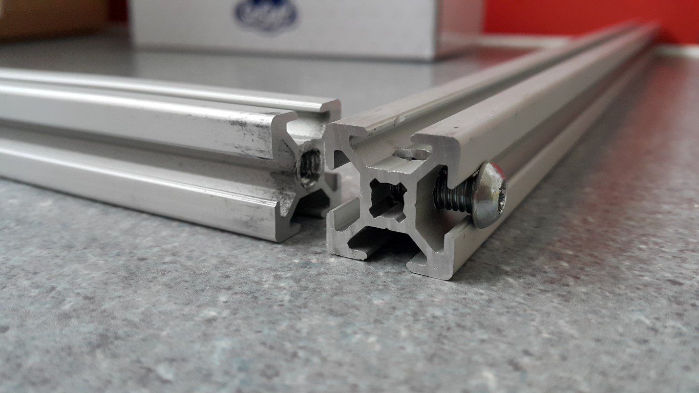
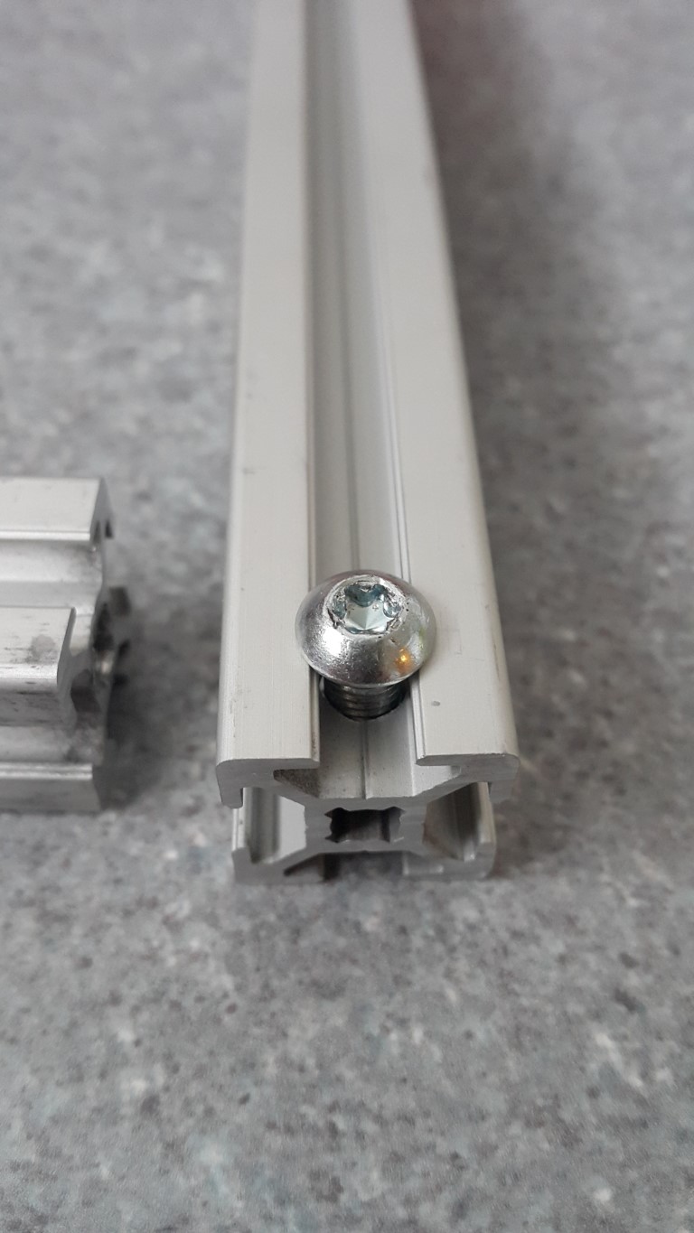
Okay so I got my smartrapcore alu kit this week, started to put it together this morning and have fallen at the first hurdle. This version of the kit does not have frame corners it has tapped extrusion ends with bolts. However the bolts are not long enough. They would be if the extrusions had been drilled to allow the bolts to sit within the extrusion but none of them are drilled as such. Am I being an idiot? Photos attached...
|
Re: Smartrapcore alu build question February 09, 2016 07:03AM |
Registered: 8 years ago Posts: 2 |


|
Re: Smartrapcore alu build question February 09, 2016 07:08AM |
Registered: 8 years ago Posts: 3,525 |
|
Re: Smartrapcore alu build question February 09, 2016 07:12AM |
Registered: 8 years ago Posts: 3,525 |
|
Re: Smartrapcore alu build question February 09, 2016 10:03AM |
Registered: 9 years ago Posts: 101 |
I too am in the process of building my ALU kit. It went together super clean here were a couple of things I encountered in case it helps anyone:
- There were no springs for bed mounting
- The hotend fan didn't spin when connected as described in the instructions. Simply fix was to wire it to the + / - mains.
- I had to experiment with the induction sensor connection to the mainboard as the pictures weren't very clear, if you hook it up like the instructions show and m119 doesn't show z-min=triggered. Flip the 2-wire connection around and try again.
I'm now at the bed leveling stage and dealing with the belt-driven z-axis... Yuck is all I can say. I was in the process of leveling things and suddenly the motor "timed out" and the bed just dropped away jacking up my belt tension. I plan to convert this to a leadscrew but I'm missing 1 printed part so we'll try to get things working as designed for a bit.
Lastly, plan to replace the power supply, they added a heatbed to this printer in the last revision. After 15 minutes it still couldn't hit 70d so I would just not bother.
Edited 1 time(s). Last edit at 02/11/2016 09:39AM by atheimer.

- There were no springs for bed mounting
- The hotend fan didn't spin when connected as described in the instructions. Simply fix was to wire it to the + / - mains.
- I had to experiment with the induction sensor connection to the mainboard as the pictures weren't very clear, if you hook it up like the instructions show and m119 doesn't show z-min=triggered. Flip the 2-wire connection around and try again.

I'm now at the bed leveling stage and dealing with the belt-driven z-axis... Yuck is all I can say. I was in the process of leveling things and suddenly the motor "timed out" and the bed just dropped away jacking up my belt tension. I plan to convert this to a leadscrew but I'm missing 1 printed part so we'll try to get things working as designed for a bit.
Lastly, plan to replace the power supply, they added a heatbed to this printer in the last revision. After 15 minutes it still couldn't hit 70d so I would just not bother.
Edited 1 time(s). Last edit at 02/11/2016 09:39AM by atheimer.
|
Re: Smartrapcore alu build question February 10, 2016 02:44AM |
Registered: 9 years ago Posts: 26 |
Quote
I'm now at the bed leveling stage and dealing with the belt-driven z-axis... Yuck is all I can say. I was in the process of leveling things and suddenly the motor "timed out" and the bed just dropped away jacking up my belt tension. I plan to convert this to a leadscrew but I'm missing 1 printed part so we'll try to get things working as designed for a bit.
In ConfigurationAdv.h:
// Default stepper release if idle. Set to 0 to deactivate.
#define DEFAULT_STEPPER_DEACTIVE_TIME 60
|
Re: Smartrapcore alu build question February 10, 2016 10:15AM |
Registered: 9 years ago Posts: 101 |
|
Re: Smartrapcore alu build question February 10, 2016 11:19AM |
Registered: 8 years ago Posts: 3,525 |
Well I've done most of the mechanical build no real problems, was missing the bed levelling screws but I've got plenty m3x20 lying around. Managed to break the "R" motor mount the part had fairly poor inter layer bonding but its easily printable on my other printers and its still attached just cracked, I think the holes weren't drilled out enough and the bolts were binding on the part.
Threaded the belts the x/y belts were easy, the z axis belt was a b#stard the retaining clip was poorly printed and needed a bunch of freeing. Also added one of those spring belt tensioners as I couldn't seem to get it taught. Is the m3 hex bolt in that area meant to be a belt tensioner (if it is its too short to do this) or a mechanical stop?
Threaded the belts the x/y belts were easy, the z axis belt was a b#stard the retaining clip was poorly printed and needed a bunch of freeing. Also added one of those spring belt tensioners as I couldn't seem to get it taught. Is the m3 hex bolt in that area meant to be a belt tensioner (if it is its too short to do this) or a mechanical stop?
|
Re: Smartrapcore alu build question February 10, 2016 12:35PM |
Registered: 9 years ago Posts: 101 |
From what I've read that bolt it meant to be a tensioner... I replaced the provided screw with a M3x25. The z-axis is still giving me issues as well, its working but really shaky.
Since this axis is only temporary I'm going to rig some sort of clamp to provide a tighter hold. I HIGHLY recommend making that Stepper_timeout change before calibration. I had a pretty tight setup on the Z until the motor timed out and the bed dropped stripping the belt loose where it lays against the other belt. I've had a hell of a time trying to re-achieve the same tension.
Curious, does your X and Y axis sound loud to you? Compared to my P3 movements sound loud somewhat grating... If I get things printing tonight I'll post a video for comparison.
|
Re: Smartrapcore alu build question February 10, 2016 12:47PM |
Registered: 8 years ago Posts: 3,525 |
|
Re: Smartrapcore alu build question February 10, 2016 01:22PM |
Registered: 8 years ago Posts: 3,525 |
|
Re: Smartrapcore alu build question February 10, 2016 06:01PM |
Registered: 8 years ago Posts: 3,525 |
Well got the build finished, inductive sensor not working at all. Tried the plug both ways around although I've had a fair bit of messing around with these sensors and I have my signal and ground the right way around (signal is black and ground is blue in the Chinese way of doing things). I've connected the 12v direct to the PSU. I have a spare sensor or two lying around so will probably try that instead and test the sensor off the printer - might even use capacitative then I don't have to worry about probing over the two strips of aluminium foil. I have some 5v regulators somewhere also as I've never had any luck with voltage dividers.
Hot end fan isn't running - I've not seen one connected to the connector used in the build instructions before (is this a software controllable fan?) suppose I could always move it to the aux 12v connector, since I don't have the z sensor plugged in there anymore.
Lcd is not working - lights up but no display, I've tried the ribbon cables in both configurations.
On the plus side the hot end heats and the heat bed heats, not had it up to 110 yet but it works on the 350w supply I am using, the presoldered heater cables are a bit wimpy.
The endstop that's mounted on the print head cable is much too short, but that's an easy fix.
I found the marlin files on github.com, might install 1.1.0 rc3.
Edited 3 time(s). Last edit at 02/10/2016 06:38PM by DjDemonD.
|
Re: Smartrapcore alu build question February 10, 2016 09:03PM |
Registered: 9 years ago Posts: 101 |
Sorry to hear about your troubles, it took me a while to get the sensor working but eventually it did, I tried connecting things a couple different ways and finally it worked. Does the sensor light ever come on?
I haven't tried the LCD yet, still trying to get a print out of this thing. A couple issues I've run into:
- Even after changing to a 500w atx power supply it takes 15 minutes to reach 65d, is there a RAMPs issue or perhaps those crappy wires you mention
- I've gotten real close to a good first layer of a test cube BUT when performing infill it doesn't print from edge to edge... I believe this means underextrusion? I haven't encountered this before, is this a trait of the bowden setup I wonder?
I had the wire the fan directly to the 12v as well.
|
Re: Smartrapcore alu build question February 10, 2016 09:40PM |
Registered: 9 years ago Posts: 101 |
|
Re: Smartrapcore alu build question February 11, 2016 03:58AM |
Registered: 9 years ago Posts: 26 |
|
Re: Smartrapcore alu build question February 11, 2016 04:55AM |
Registered: 8 years ago Posts: 3,525 |
atheimer - sensor light does not come on at all, I think probably a duff sensor or loose connection in the voltage divider, I have spares so will set up a spare one with a voltage regulator on the signal line (much more reliable/efficient and still only £1), and then test the supplied one later when I have time (never). I would definitely put some non-conductive insulation under the bed and some on top during heating. I note from the firmware the #define MAX_BED_POWER 230 could be upped to 255 the bed is currently being underpowered. However I would replace the cables with the type used on the hot end (or even thicker gauge) the idea of 11amps through those little wires is a tad worrying, this is probably why they've limited bed power. You can also, if you have an adjustable power supply, nudge the voltage up to 13.2v which improves bed/hot end heating by 10%, and means slightly lower current flow due to higher voltage (hence ideally 24v bed heaters) but doesn't cause any problems with anything else.
Also the way they wire the 12v main power connector to the ramps is not great. You want to supply two 12v rails one into each input , not to bridge the inputs with those little link cables, this is where many people get fires/overheating. I am using two 13A mains voltage cables to connect the two inputs to two of the rails rails on my 350w "brick style" PSU.
If the infill doesn't reach the perimeters then that's under extrusion so perhaps too few esteps, or wrong nozzle size/filament diameter etc.. I am not in the Bowden camp, generally they are harder to tune and there is more uncertainty - such as greater friction in the bowden tube at extreme coordinates, the need for much faster and longer retraction which increases the risk of nozzle clogging etc... It should be possible to add a direct drive extruder to the print head, maybe based on a geared nema 11 motor so only 250-300g mass added. Or relocate the extruder to anywhere which shortens the bowden tube to the absolutely shortest length that will still function.
s0me - I'll try that - I take it that the pot on the back affects brightness of the liquid crystal not the backlight? My back light is on and shining brightly.
Edited 2 time(s). Last edit at 02/11/2016 06:16AM by DjDemonD.
|
Re: Smartrapcore alu build question February 11, 2016 06:24AM |
Registered: 8 years ago Posts: 3,525 |
Talking of bowden I was contemplating making a flying extruder for the smartrapcore alu, like this one some of us have made for deltas. flying extruder so essentially suspending the extruder on elastic above the head, with as short a bowden tube as possible which allows the extruder to pivot around as the head moves but keeps the bowden tube short. It wont look neat as it doesn't sit within the frame like it does on a delta, and the range of movement of the head is greater so I am not sure if it would work.
I am going to put my flex3drive into action though, its the logical thing to do on this printer, 50g and direct drive - you can't beat that, provided it works as well as everyone says it does.
I am going to put my flex3drive into action though, its the logical thing to do on this printer, 50g and direct drive - you can't beat that, provided it works as well as everyone says it does.
|
Re: Smartrapcore alu build question February 11, 2016 09:37AM |
Registered: 9 years ago Posts: 101 |
I tried to adjust the contrast on my display this morning and couldn't get anything to show up -in any direction. Hopefully you have better luck.
Thanks for sharing your wiring experience, the bed wires and solder job are pretty bad so that's where I'll start. I too re-wired the power connections, I've never seen a jumper like that used before.
I looked at that flex-drive system, looks pretty cool. Since this is my first Bowden setup I'll play for a while yet and if I can't get to the point of consistently awesome prints I'll be eager to hear how its working for you.
Do you print on glass or straight on the aluminum? My old P3 printed directly on the aluminum and worked quite well for PLA but PETG never stuck well and I think it might be time to try something new.
|
Re: Smartrapcore alu build question February 11, 2016 12:27PM |
Registered: 8 years ago Posts: 3,525 |
I print on printbite on my i3 and borosilicate 4mm glass on my kossel. I have printed onto the "back" surface of a mk3 heatbed with the aluminium spreader built in, using hairspray for abs fairly successfully but its messy and the aluminium gets scratched. I haven't printed with PET-G.
Print bite is very good, no adhesion promoter required, and self release once it cools. ABS still warps without a heated chamber but almost none with a heated chamber at 45 deg C. The only thing is, it needs an expensive, thin, heat resistant adhesive such as 3M 8153LE to bond it to your glass/aluminium bed so that it is even and doesn't peel off. My suggestion to the maker Mutley3d is to consider selling it professionally bonded to an aluminium plate which can then just be clipped onto your printer, but he sells it in custom sizes so this would probably be a headache.
I am probably going to replace all my PLA smartrapcore alu parts with my own printed ABS parts as I intend for it to become an enclosed heated printer at some point. I also intend to move the x and y motors to the other side of the extrusion so they are out of the enclosed area. The flex3drive motor will be out of the enclosure, and I intend to build a twin leadscrew (or maybe even push the boat out and go to twin ballscrew ) z axis, with its motor situated outside the enclosed area.
All in all I am looking forward to it immensely but like you I need to prove the machine is worthy of all of this attention first.
|
Re: Smartrapcore alu build question February 11, 2016 08:05PM |
Registered: 9 years ago Posts: 101 |
I actually just ordered some Printbite, I found it when you sent me the link to flex3drive... and it gets rav reviews pretty much everywhere. Any variable I can minimize I'll take!
Did you use the aformentioned 3M product to attach things:
[www.amazon.com]
Did you use the aformentioned 3M product to attach things:
[www.amazon.com]
|
Re: Smartrapcore alu build question February 12, 2016 02:12AM |
Registered: 8 years ago Posts: 3,525 |
Okay so reason why x and y are noisy (and motors quite hot) the stepper driver current is set quite high out of the box. I'm getting acceptable movement now with the drivers set 1/4 turn clockwise from their minimum position.
Got the inductive sensor working by rewiring it with a voltage regulator, it was the voltage divider that was broken. Why didn't they back the entire glass in foil, its crazy only being able to probe along two strips its a recipe for head crashes.
Still no Lcd despite trying a few different settings in config.
Edited 1 time(s). Last edit at 02/12/2016 03:48AM by DjDemonD.
|
Re: Smartrapcore alu build question February 12, 2016 03:45AM |
Registered: 8 years ago Posts: 3,525 |
Quote
atheimer
I actually just ordered some Printbite, I found it when you sent me the link to flex3drive... and it gets rav reviews pretty much everywhere. Any variable I can minimize I'll take!
Did you use the aformentioned 3M product to attach things:
[www.amazon.com]
Yes that works very well I've only used it to stick printbite to aluminium. I think Mutley supplies it now with double sided tape already applied he's got a line on a bulk quantity of 3m 468p which I think is even more robust.
Edited 1 time(s). Last edit at 02/12/2016 03:47AM by DjDemonD.
|
Re: Smartrapcore alu build question February 12, 2016 06:37AM |
Registered: 8 years ago Posts: 3,525 |
I've just been through the 1.0.0 config line by line, porting the settings over to a clean version of 1.1.0 rc3.
I did turn up a few glaring errors and oversights.
I have not yet checked pins.h to see if there is anything different but given we have decided to ignore the fan pin assignment and go with direct/aux 12v instead I can't see any non-standard pin assignments on this printer.
The following changes refer to 1.1.0 RC3 as some settings are laid out in a different/less confusing? way.
#define TEMP_SENSOR_1 -1 I can see no reason to set temp sensor 1 which is redundant on this machine to -1 which is a thermocouple change it to 0
should be
#define TEMP_SENSOR_1 0
as we said before with decent wiring this line should read
#define MAX_BED_POWER 255
I personally prefer thermal protection ON but set the parameters fairly loosely so it doesn't trigger unless things are badly out of shape. I use 60 seconds and 10 degrees hysteresis.
I have opted to enable min and max software endstops as follows
#define min_software_endstops true // If true, axis won't move to coordinates less than HOME_POS.
#define max_software_endstops true // If true, axis won't move to coordinates greater than the defined lengths below.
// @section machine
// Travel limits after homing (units are in mm)
#define X_MIN_POS 20
#define Y_MIN_POS 52
#define Z_MIN_POS 0
#define X_MAX_POS 190
#define Y_MAX_POS 222
#define Z_MAX_POS 160
Which should prevent any x/y axis crashes once homed (the exact values will be a few mm different on each printer)
I haven't yet looked at the autolevel grid coordinate definition (always a pain in the arse), but this will have to be much more carefully defined for this printer, as the inductive sensor will only trigger when over the metal film strips under the glass, so definitely looking to place a full metal coating (wondering if cooking foil will work) under the glass or use an aluminium plate.
One hugely glaring error - the ABL probe offsets are not set at all. This will cause off-bed probing (head crash) or a compile error when using the software endstops, I am at work at the moment, so can't measure them but will do so when I get home. One thing I came to realise on my i3 when messing around with ABL probes - the offset refers to the probe's trigger point not the physical end of the probe. Knowing this key piece of information really helped (perhaps I was just being an idiot).
Will need to alter #define Z_SAFE_HOMING_X_POINT and #define Z_SAFE_HOMING_Y_POINT to ensure the z homing point is over the metallic strips. Whether I have my bed the wrong way around or what I dont know but my only attempt to do a g28 resulted in a head crash.
I am hoping that the LCD works on Marlin 1.1.0 RC3 as the LCD config is less complicated. The reprap wiki says for Marlin 1.0.0 to get the reprap_discount_smart_controller working you have to #define NEWPANEL as well as #define REPRAP_DISCOUNT_SMART_CONTROLLER which isn't a default option. So if anyone is thinking about sticking to 1.0.0 then consider adding #define ULTIPANEL and #define NEWPANEL to this region of config and see if the LCD works now. Or just define ultipanel instead which has the same effect, as far as I can see.
Babystepping is available on 1.1.0 rc3 for z axis on corexy so this is well worth having since the wobbly bed is likely to cause all manner of first layer woes even with ABL in use. You can get to it via "tune" on the LCD once printing has started, print a big long set of loops before your part and babystep the z axis to its optimum. I think you can then do an m500/save settings to save the z offset generated - but don't quote me on that. If not make a note of the z coordinate on the lcd and after babystepping it and then alter the z-probe offset or add/subtract it in your slicer software.
I havent uploaded 1.1.0 rc3 yet to the printer,but I am quite confident it will work once the correct probe offsets are entered.
|
Re: Smartrapcore alu build question February 12, 2016 11:11AM |
Registered: 9 years ago Posts: 101 |
Thanks for posting all your work, this is really helpful to see!
Here is where I have mine set so far. They are not perfect but they appear to create a safe environment. So far with these numbers I can:
- Run G28 and everything homes correctly
- Run G29 to autolevel, for me this is pretty good and safely inside the screws on the edge of the bed
- Execute a print, my 20x20 test cube was just a little off-center but not terrible, definitely a safe and solid starting point.
// Travel limits after homing
#define X_MAX_POS 180
#define X_MIN_POS 0
#define Y_MAX_POS 180
#define Y_MIN_POS 0
#define Z_MAX_POS 160
#define Z_MIN_POS 0
and my offsets:
#define X_PROBE_OFFSET_FROM_EXTRUDER 35
#define Y_PROBE_OFFSET_FROM_EXTRUDER -5
#define Z_PROBE_OFFSET_FROM_EXTRUDER 0
and my auto-probe grid cords:
// set the rectangle in which to probe
#define LEFT_PROBE_BED_POSITION 20 //distance from x endstop
#define RIGHT_PROBE_BED_POSITION 130 //max x distance
#define BACK_PROBE_BED_POSITION 180 //max y distance
#define FRONT_PROBE_BED_POSITION 60 //distance from y endstop
One thing I would like to understand (being new to RAMPS config) the // Travel limits after homing parameters
I have read that these numbers are relative from the center of the bed and that x-min should pretty much always be a negative number. From playing with these numbers I know this isn't the case but have yet to completely understand what
they are doing in a CoreXY setup. The settings I listed above cause the z-axis to home in the near-middle of the printbed = good and safe and land my print very close to the middle of the bed but I would really like to understand what is happening.
Given your numbers, if you home both X&Y and then issue G1 X0 Y0 does the printhead move away from the endstops and go to the front-left corner of the bed?
Edited 1 time(s). Last edit at 02/12/2016 11:39AM by atheimer.
|
Re: Smartrapcore alu build question February 12, 2016 11:17AM |
Registered: 8 years ago Posts: 3,525 |
Edit- I know what you're saying about these limits - are they relative or absolute? Setup the way I have it (tried these settings on 1.0.0 briefly) it would move around the bed but not outside of it after homing using the movement controls in pronterface, but I know if you send g1 x1 y1 it will move to these coordinates. I sliced a model once without changing slicer config from i3 to kossel and the kossel tried to move to the coordinates required on the i3 with worrying results.
In my scheme my print area begins at x20, y52 and ends at x190, y222. I do not know how well this will work when printing, I've never had a printer that homes outside the bed area, but I think I can define this bed shape in slic3r. Or in pronterface maybe, I know you can do this in repetier host which I might use as you can run multiple instances.
Edited 2 time(s). Last edit at 02/12/2016 11:30AM by DjDemonD.
|
Re: Smartrapcore alu build question February 13, 2016 04:11AM |
Registered: 8 years ago Posts: 3,525 |
Progress so far. Got 1.1.0 rc3 uploaded and it works. Determined that one answer to the problem with the coordinates is to use standard travel limits from 0 to 170 etc but define manual homing switch positions x= -20 y= -52 so it homes at the physical endstops, but then after that moves from 0,0 at front left of the bed.
Extruder is extremely inconsistent when asking for 50mm I get 45,55,58 etc... The idler pulley is tight against the filament but there aren't any springs or screws holding the idler tension. There are holes for them so I assume they were not supplied.
Got rid of the metal strips under the glass and replaced them with a double thickness of kitchen foil, which triggers the sensor across the entire bed. Got the bed physically level and the ABL grid defined.
Tried a test cube it was fairly late by then, but could not get pla to stick at all. So I think it's just a case of getting the z offset right.
I swapped the smartrap supplied Lcd onto my i3 which also has a reprap discount smart controller but it didn't work, then put my other Lcd onto the smartrap and it didn't work. I think it's a duff Lcd and a duff header board also. So I've ordered a full graphics smart controller (£22 delivered) as I haven't played with one before.
|
Re: Smartrapcore alu build question February 13, 2016 11:12AM |
Registered: 9 years ago Posts: 101 |
Great to hear you figured out the positioning bit, I'm away from my machine this weekend but what you said in paragraph 1 makes sense based on my experience.
I have actually been surprised by the extruder and the hotend. I think I told you I have an E3D and Wades sitting around but so far have no complaints about the stock setup. I sat and looked at the extruder with no springs and wondered how it was going to work but it hasn't clicked once, something my bulldog still does every once in a while.
Here's a funny one, is your heatbed an MK2b or MK3? I have used only Aluminum heatbeds on my other printers, in fact I have 2 extra sitting around. The one that came with the kit looked identical so I just assumed it was mk3... if its not that would explain why it doesn't heat up well -but my induction sensor works great
I found the bed-leveling and z-offset setup to be a breeze on this printer. My P3 took me hours... again....
I set first layer width to 150%, that fixed my under-extrusion on my test cube first layer. Other than that the stock settings in the INI file worked for a decent cube.
I read somewhere else that the RAMPS + CoreXY won't have enough brains to drive the Smart Graphic Controller... try [forums.reprap.org]
I agree with your findings though, I tried this lcd in a different machine, an old Smart Graphic in this machine and nothing has worked. I did msg SmartFriendz about it but have not heard back yet.
I think I'd probably switch to a Duet mainboard + PanelDue (like my P3 runs) before spending much more on this... but we'll see. LCD is nice but I can live without it.
Would you be able to GIT your Marlin files? Or perhaps upload them for me? We might as well work off the same firmware.
|
Re: Smartrapcore alu build question February 13, 2016 01:07PM |
Registered: 8 years ago Posts: 3,525 |
It's amazing the (in)consistency of these things and how each person experiences them. I think the extruder is so far awful, mine has been clicking and stalling badly. So I'm currently messing with stepper current and idler tension to try to get it running smoothly. When it arrived the drive gear position on the motor shaft was too much towards the outside of the extruder meaning the filament had to kink to go through it. So I loosened the grub screw and pushed it back in only to realise that the grub screw fouls the idler. So maybe it could be properly aligned but I'd have to grind a proper flat onto the motor shaft, which is round at the moment. Thinking about a longer motor I've got some lying around.
The hot end is okay, the filament isn't sliding into it that smoothly and the nozzle is far too sharp edged for my liking. What nozzle size do you think it is, I haven't got the micro drills out to measure it yet? I think one drawback of preassembled modules is that you have to trust they're assembled to a good standard. It'll get rebuilt after the first jam, I'm printing pla so shouldn't be long.
The supplied heatbed I have is a mk2b. I use a mk3 on my i3 but I might swap them over as I intend for the smartrap to replace the i3 if it's good enough. I'm not having too much trouble heating mine up, I'd say it's quicker than my mk3 but there a lot less mass. It might be worth measuring the resistance of your bed to see if it is correct maybe it's a duff unit. Is the link from pads 2 and 3 decent also?
I have got my Lcd working changed some setting in marlin and turned the pot on it a few times in each direction and its working now. I'll try the full graphic and see how fast I can run the smart core before it stutters, it's worse on deltas but my kossel runs a t3p3 panelone controller up to 80 mm/s without too much fuss. The kinematic calculations are far less demanding on a corexy.
Yeah very happy to share files I haven't used github except to download but I'm sure it's easy enough.
Edited 2 time(s). Last edit at 02/13/2016 02:16PM by DjDemonD.
|
Re: Smartrapcore alu build question February 13, 2016 03:36PM |
Registered: 9 years ago Posts: 101 |
My guess on the nozzle is .4mm based on the test prints I've based most of my initial settings on my experience with that nozzle size and I've had satisfactory results.
What setting did the trick for the LCD? Curious to see if I can get it working with the original firmware for the fun of it -before I upgrade to the latest.
What setting did the trick for the LCD? Curious to see if I can get it working with the original firmware for the fun of it -before I upgrade to the latest.
|
Re: Smartrapcore alu build question February 13, 2016 03:54PM |
Registered: 8 years ago Posts: 3,525 |
Good news, managed to print something, a quite squishy cube but at least it's printing. The extruder was being underpowered and the idler was nowhere near tight enough. Now to see if I can get this cube, cube shaped and see if it is the right dimensions. Its PLA and theres no part cooling at present so its a bit melted, plus my extruder temp was fairly high for pla (210) since I wondered if I was having extrusion problems due to the thermistor reading higher than the actual temperature, so I turned it up a bunch.
The machine's kinematics are quite nice, its not the beautiful dance of the delta, but it seems much more effortless than a cartesian axis printer. I turned it up to 140% in pronterface from the standard slic3r speed settings (never really sure what this is mm/s) and it seemed very happy.
I'd agree on the nozzle but I will verify it at some point.
I think I might remix their supplied hot end cooler, to include a part cooling duct I made one for the kossel mini kossel mini e3d v5 multifunction fan shroud. The smartfriendz one is basically the same shape, but neater and cleaner, so with the addition of a duct would work quite well. I find this more than enough printing PLA on the kossel, no need to add a second fan and duct to the print head mass. Since these hot end heatbreaks can be adequately cooled with 30mm fans with tight fitting shrouds eg e3d, the small amount of diverted air to cool the part shouldn't compromise cooling the heatbreak, with a 40mm fan. If I'm printing ABS I just cover the duct outlet, so no additional complexity of firmware controlled fans.
As for the LCD - the config is different in 1.1.0 rc3 than 1.0.0 but this is how it reads
So it was as simple as it looks, its much more simple than in the earlier release of Marlin, there's only 4 lines uncommented.
Btw its much easier to read on github isn't it, only the uncommented lines are highlighted.
The machine's kinematics are quite nice, its not the beautiful dance of the delta, but it seems much more effortless than a cartesian axis printer. I turned it up to 140% in pronterface from the standard slic3r speed settings (never really sure what this is mm/s) and it seemed very happy.
I'd agree on the nozzle but I will verify it at some point.
I think I might remix their supplied hot end cooler, to include a part cooling duct I made one for the kossel mini kossel mini e3d v5 multifunction fan shroud. The smartfriendz one is basically the same shape, but neater and cleaner, so with the addition of a duct would work quite well. I find this more than enough printing PLA on the kossel, no need to add a second fan and duct to the print head mass. Since these hot end heatbreaks can be adequately cooled with 30mm fans with tight fitting shrouds eg e3d, the small amount of diverted air to cool the part shouldn't compromise cooling the heatbreak, with a 40mm fan. If I'm printing ABS I just cover the duct outlet, so no additional complexity of firmware controlled fans.
As for the LCD - the config is different in 1.1.0 rc3 than 1.0.0 but this is how it reads
//==============================LCD and SD support=============================
// @section lcd

// Define your display language below. Replace (en) with your language code and uncomment.
// en, pl, fr, de, es, ru, bg, it, pt, pt-br, fi, an, nl, ca, eu, kana, kana_utf8, cn, test
// See also language.h
#define LANGUAGE_INCLUDE GENERATE_LANGUAGE_INCLUDE(en)

// Choose ONE of these 3 charsets. This has to match your hardware. Ignored for full graphic display.
// To find out what type you have - compile with (test) - upload - click to get the menu. You'll see two typical lines from the upper half of the charset.
// See also documentation/LCDLanguageFont.md
  #define DISPLAY_CHARSET_HD44780_JAPAN        // this is the most common hardware
  //#define DISPLAY_CHARSET_HD44780_WESTERN
  //#define DISPLAY_CHARSET_HD44780_CYRILLIC

//#define ULTRA_LCD  //general LCD support, also 16x2
//#define DOGLCD  // Support for SPI LCD 128x64 (Controller ST7565R graphic Display Family)
#define SDSUPPORT // Enable SD Card Support in Hardware Console
// Changed behaviour! If you need SDSUPPORT uncomment it!
//#define SDSLOW // Use slower SD transfer mode (not normally needed - uncomment if you're getting volume init error)
//#define SDEXTRASLOW // Use even slower SD transfer mode (not normally needed - uncomment if you're getting volume init error)
//#define SD_CHECK_AND_RETRY // Use CRC checks and retries on the SD communication
//#define ENCODER_PULSES_PER_STEP 1 // Increase if you have a high resolution encoder
//#define ENCODER_STEPS_PER_MENU_ITEM 5 // Set according to ENCODER_PULSES_PER_STEP or your liking
//#define ULTIMAKERCONTROLLER //as available from the Ultimaker online store.
//#define ULTIPANEL  //the UltiPanel as on Thingiverse
//#define SPEAKER // The sound device is a speaker - not a buzzer. A buzzer resonates with his own frequency.
//#define LCD_FEEDBACK_FREQUENCY_DURATION_MS 100 // the duration the buzzer plays the UI feedback sound. ie Screen Click
//#define LCD_FEEDBACK_FREQUENCY_HZ 1000         // this is the tone frequency the buzzer plays when on UI feedback. ie Screen Click
                                                 // 0 to disable buzzer feedback. Test with M300 S P
// PanelOne from T3P3 (via RAMPS 1.4 AUX2/AUX3)
// [reprap.org]
//#define PANEL_ONE

// The MaKr3d Makr-Panel with graphic controller and SD support
// [reprap.org]
//#define MAKRPANEL

// The Panucatt Devices Viki 2.0 and mini Viki with Graphic LCD
// [panucatt.com]
// ==> REMEMBER TO INSTALL U8glib to your ARDUINO library folder: [code.google.com]
//#define VIKI2
//#define miniVIKI

// This is a new controller currently under development.  [github.com]
//
// ==> REMEMBER TO INSTALL U8glib to your ARDUINO library folder: [code.google.com]
//#define ELB_FULL_GRAPHIC_CONTROLLER
//#define SD_DETECT_INVERTED

// The RepRapDiscount Smart Controller (white PC
// [reprap.org]
#define REPRAP_DISCOUNT_SMART_CONTROLLER

// The GADGETS3D G3D LCD/SD Controller (blue PC
// [reprap.org]
//#define G3D_PANEL

// The RepRapDiscount FULL GRAPHIC Smart Controller (quadratic white PC
// [reprap.org]
//
// ==> REMEMBER TO INSTALL U8glib to your ARDUINO library folder: [code.google.com]
//#define REPRAP_DISCOUNT_FULL_GRAPHIC_SMART_CONTROLLER

// The RepRapWorld REPRAPWORLD_KEYPAD v1.1
// [reprapworld.com]
//#define REPRAPWORLD_KEYPAD
//#define REPRAPWORLD_KEYPAD_MOVE_STEP 10.0 // how much should be moved when a key is pressed, eg 10.0 means 10mm per click

// The Elefu RA Board Control Panel
// [www.elefu.com]
// REMEMBER TO INSTALL LiquidCrystal_I2C.h in your ARDUINO library folder: [github.com]
//#define RA_CONTROL_PANEL

// The MakerLab Mini Panel with graphic controller and SD support
// [reprap.org]
//#define MINIPANEL

/**
 * I2C Panels
 */

//#define LCD_I2C_SAINSMART_YWROBOT

// PANELOLU2 LCD with status LEDs, separate encoder and click inputs
//
// This uses the LiquidTWI2 library v1.2.3 or later ( [github.com] )
// Make sure the LiquidTWI2 directory is placed in the Arduino or Sketchbook libraries subdirectory.
// (v1.2.3 no longer requires you to define PANELOLU in the LiquidTWI2.h library header file)
// Note: The PANELOLU2 encoder click input can either be directly connected to a pin
//       (if BTN_ENC defined to != -1) or read through I2C (when BTN_ENC == -1).
//#define LCD_I2C_PANELOLU2

// Panucatt VIKI LCD with status LEDs, integrated click & L/R/U/P buttons, separate encoder inputs
//#define LCD_I2C_VIKI

// SSD1306 OLED generic display support
// ==> REMEMBER TO INSTALL U8glib to your ARDUINO library folder: [code.google.com]
//#define U8GLIB_SSD1306

// Shift register panels
// ---------------------
// 2 wire Non-latching LCD SR from:
// [bitbucket.org]
// LCD configuration: [reprap.org]
//#define SAV_3DLCD

// @section extras

// Increase the FAN pwm frequency. Removes the PWM noise but increases heating in the FET/Arduino
//#define FAST_PWM_FAN

// Use software PWM to drive the fan, as for the heaters. This uses a very low frequency
// which is not as annoying as with the hardware PWM. On the other hand, if this frequency
// is too low, you should also increment SOFT_PWM_SCALE.
//#define FAN_SOFT_PWM

// Incrementing this by 1 will double the software PWM frequency,
// affecting heaters, and the fan if FAN_SOFT_PWM is enabled.
// However, control resolution will be halved for each increment;
// at zero value, there are 128 effective control positions.
#define SOFT_PWM_SCALE 0

// Temperature status LEDs that display the hotend and bet temperature.
// If all hotends and bed temperature and temperature setpoint are < 54C then the BLUE led is on.
// Otherwise the RED led is on. There is 1C hysteresis.
//#define TEMP_STAT_LEDS

// M240  Triggers a camera by emulating a Canon RC-1 Remote
// Data from: [www.doc-diy.net]
//#define PHOTOGRAPH_PIN     23

// SkeinForge sends the wrong arc g-codes when using Arc Point as fillet procedure
//#define SF_ARC_FIX

// Support for the BariCUDA Paste Extruder.
//#define BARICUDA

//define BlinkM/CyzRgb Support
//#define BLINKM
// [reprap.org]
#define REPRAP_DISCOUNT_SMART_CONTROLLER
// The GADGETS3D G3D LCD/SD Controller (blue PC
// [reprap.org]
//#define G3D_PANEL
// The RepRapDiscount FULL GRAPHIC Smart Controller (quadratic white PC
// [reprap.org]
//
// ==> REMEMBER TO INSTALL U8glib to your ARDUINO library folder: [code.google.com]
//#define REPRAP_DISCOUNT_FULL_GRAPHIC_SMART_CONTROLLER
// The RepRapWorld REPRAPWORLD_KEYPAD v1.1
// [reprapworld.com]
//#define REPRAPWORLD_KEYPAD
//#define REPRAPWORLD_KEYPAD_MOVE_STEP 10.0 // how much should be moved when a key is pressed, eg 10.0 means 10mm per click
// The Elefu RA Board Control Panel
// [www.elefu.com]
// REMEMBER TO INSTALL LiquidCrystal_I2C.h in your ARDUINO library folder: [github.com]
//#define RA_CONTROL_PANEL
// The MakerLab Mini Panel with graphic controller and SD support
// [reprap.org]
//#define MINIPANEL
/**
* I2C Panels
*/
//#define LCD_I2C_SAINSMART_YWROBOT
// PANELOLU2 LCD with status LEDs, separate encoder and click inputs
//
// This uses the LiquidTWI2 library v1.2.3 or later ( [github.com] )
// Make sure the LiquidTWI2 directory is placed in the Arduino or Sketchbook libraries subdirectory.
// (v1.2.3 no longer requires you to define PANELOLU in the LiquidTWI2.h library header file)
// Note: The PANELOLU2 encoder click input can either be directly connected to a pin
// (if BTN_ENC defined to != -1) or read through I2C (when BTN_ENC == -1).
//#define LCD_I2C_PANELOLU2
// Panucatt VIKI LCD with status LEDs, integrated click & L/R/U/P buttons, separate encoder inputs
//#define LCD_I2C_VIKI
// SSD1306 OLED generic display support
// ==> REMEMBER TO INSTALL U8glib to your ARDUINO library folder: [code.google.com]
//#define U8GLIB_SSD1306
// Shift register panels
// ---------------------
// 2 wire Non-latching LCD SR from:
// [bitbucket.org]
// LCD configuration: [reprap.org]
//#define SAV_3DLCD
// @section extras
// Increase the FAN pwm frequency. Removes the PWM noise but increases heating in the FET/Arduino
//#define FAST_PWM_FAN
// Use software PWM to drive the fan, as for the heaters. This uses a very low frequency
// which is not as annoying as with the hardware PWM. On the other hand, if this frequency
// is too low, you should also increment SOFT_PWM_SCALE.
//#define FAN_SOFT_PWM
// Incrementing this by 1 will double the software PWM frequency,
// affecting heaters, and the fan if FAN_SOFT_PWM is enabled.
// However, control resolution will be halved for each increment;
// at zero value, there are 128 effective control positions.
#define SOFT_PWM_SCALE 0
// Temperature status LEDs that display the hotend and bet temperature.
// If all hotends and bed temperature and temperature setpoint are < 54C then the BLUE led is on.
// Otherwise the RED led is on. There is 1C hysteresis.
//#define TEMP_STAT_LEDS
// M240 Triggers a camera by emulating a Canon RC-1 Remote
// Data from: [www.doc-diy.net]
//#define PHOTOGRAPH_PIN 23
// SkeinForge sends the wrong arc g-codes when using Arc Point as fillet procedure
//#define SF_ARC_FIX
// Support for the BariCUDA Paste Extruder.
//#define BARICUDA
//define BlinkM/CyzRgb Support
//#define BLINKM
So it was as simple as it looks, its much more simple than in the earlier release of Marlin, there's only 4 lines uncommented.
Btw its much easier to read on github isn't it, only the uncommented lines are highlighted.

Sorry, only registered users may post in this forum.