Madmike8's Funbot build #2
Posted by madmike8
|
Madmike8's Funbot build #2 March 30, 2015 07:51PM |
Registered: 10 years ago Posts: 814 |
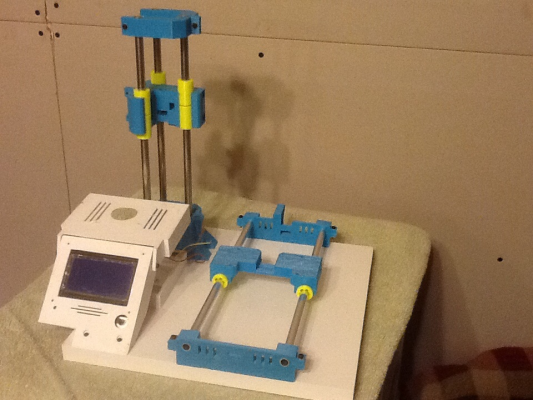
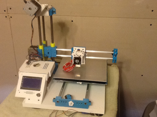
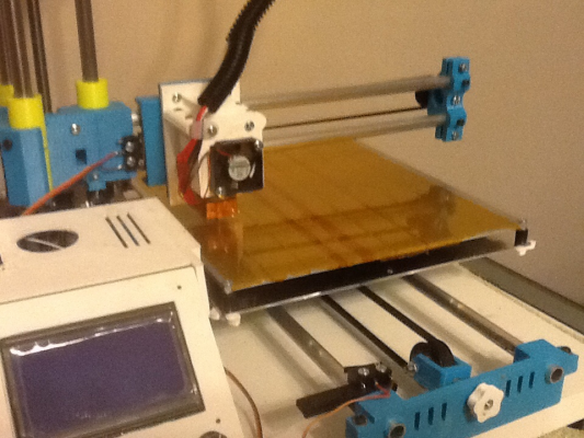
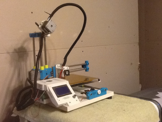
The Funbot i1 is a variant of the Smartrap, that Cliff Mellangård made while experimenting upgrades on his Smartrap. I had followed Cliff's work through both his plastic and wooden versions of the Smartrap, and when he released this one it was perfect timing for me. I was wanting a small printer to have in my work office to print PLA only. This seemed to fit.
Funbot - Thingiverse Link
Funbot - Reprap Wiki Link
Link to the start of my first Funbot
Thingiverse link to my First Funbot build
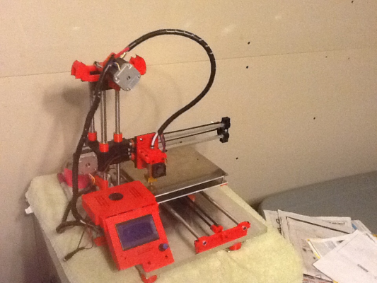
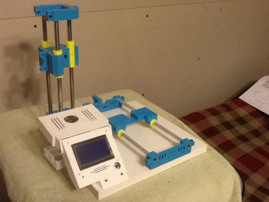
Here's a pic of my first one. Mine differed from Ciff's in that I used the U.S. 3/8" rods rather than 10mm, aluminum tubes for the X and Y axis, and I also used bronze bushings and a bowden extruder setup instead of direct drive. I purchased the rods,tubes, and bushings at servocity.com
I used a Regpye Mk1 hotend.
I've been really happy with it. I've had a couple request to make some for friends and family, so I thought I'd document my second build here.
For the second one I'm going to use 3/8" drill rods purchased locally at Fastenal. They also have the bronze bushings and M8 threaded rod there.
I will be using PLA bushings though. I will use a Chinese all metal J-Head, and some $5 steppers that I had purchased on sale.
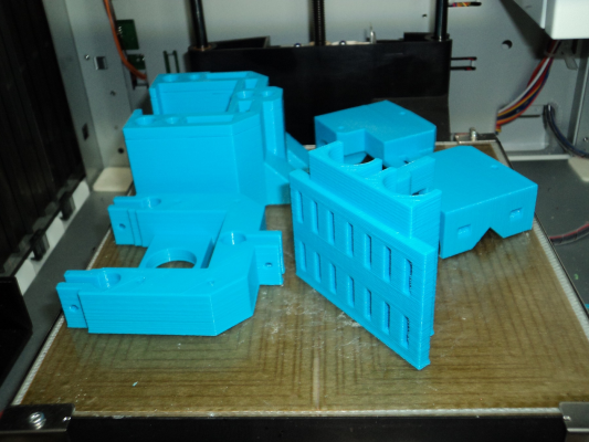
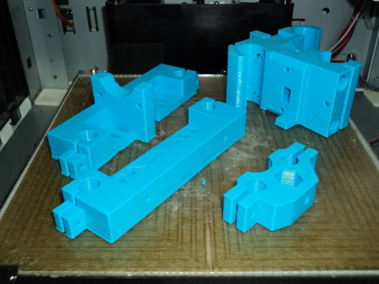
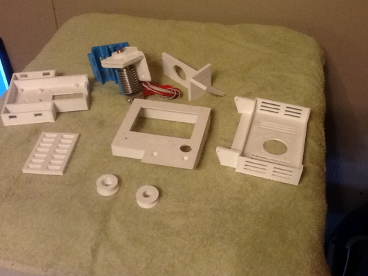
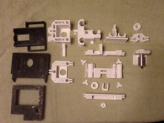
Well except for the Y bearing holder, I have the first set of parts printed in blue. The rest of it will be in white.
As I'm working on a few projects at once, updates will be slower... but steady. I have all the parts aside from some screws and the bed plates.
Mike
Edited 1 time(s). Last edit at 03/30/2015 07:56PM by madmike8.
|
Re: Madmike8's Funbot build #2 March 30, 2015 11:18PM |
Registered: 10 years ago Posts: 43 |
|
Re: Madmike8's Funbot build #2 March 31, 2015 12:12AM |
Registered: 9 years ago Posts: 17 |
|
Re: Madmike8's Funbot build #2 March 31, 2015 01:26AM |
Registered: 10 years ago Posts: 814 |
On the Davinci I use ABS. On the Funbot I use PLA. I'd say print quality is about the same. The PLA bushings I'll be using on this Funbot was printed with the first one.
The first Funbot is on my desk at work, so I don't get to print on it as much as I want. My Ord Bot is torn down for a rebuild.
My wife got me the Davinci for Christmas, I really thought I wouldn't like it after reading some reviews, but it's actually been a nice printer.
The first Funbot is on my desk at work, so I don't get to print on it as much as I want. My Ord Bot is torn down for a rebuild.
My wife got me the Davinci for Christmas, I really thought I wouldn't like it after reading some reviews, but it's actually been a nice printer.
|
Re: Madmike8's Funbot build #2 March 31, 2015 10:07AM |
Registered: 10 years ago Posts: 148 |
|
Re: Madmike8's Funbot build #2 March 31, 2015 10:45AM |
Registered: 10 years ago Posts: 814 |
|
Re: Madmike8's Funbot build #2 March 31, 2015 02:36PM |
Registered: 9 years ago Posts: 2 |
|
Re: Madmike8's Funbot build #2 April 03, 2015 01:26AM |
Registered: 10 years ago Posts: 814 |
|
Re: Madmike8's Funbot build #2 April 10, 2015 08:17PM |
Registered: 10 years ago Posts: 814 |
I was asked for a filament use for the Funbot. Here's the list for the individual parts in meters with infill%.
Z base v4 - 37.928m 50%
Z carriage v7 - 28.350m 50%
z base top v1 - 12.666m 30%
y upgrade v1 - 37.046m 30%
y pulley holder - 1.112m 30%
x end v2 - 3.933m 30%
x carriage v3b - 11.195m 30%
ramps cover v1 - 14.331m 10%
lcd v2 - 16.345m 10%
624zz to 22mm (x2) - 0.946m 30%
electronics base - 13.894m 10%
extruder plate - 4.579m 30%
bed drill template - 5.551m 10%
funbot small parts - 7.363m 10%
spool holder (x2) - 7.923m 20%
bowden mk7 extruder - 4.832m 30%
extruder support - 8.447m 20%
funbot foot v2 (x4)- 1.901m 10%
jhead hotend mount - 8.001m 30%
jhead fan mount - 2.626m 15%
bushing bearing v3 (x14) - 1.247m 10%
Funbot BOM
Screws (I always buy extras... you'll end up needing them)
50mm M4 Qty 1
50mm M4 screw x1 X idler bearing mounting.
(I used a 70mm I had on hand. 50mm would do it.)
18mm M4 Qty 1
18mm M4 screw x1 Y idler bearing mounting.
50mm M3 Qty 9
50mm M3 screws x5 z base / stepper mounting.
50mm M3 screws x2 Y Stepper mounting.
50mm M3 screws x2 X axis Stepper mounting.
30mm M3 Qty 7
30mm M3 screw x1 Y belt tensioner.
30mm M3 screws x2 LCD cover to base plate mounting.
30mm M3 screws x4 Y lower plate to Y upper plate mounting
25mm M3 Qty 4
25mm M3 screws x4 Y axis mounting.
20mm M3 Qty 9
20mm M3 screws x2 electronics bottom mounting.
20mm M3 screws x2 Y endstop base mounting.
20mm M3 screws x2 Fan mount to RAMPS cover.
20mm M3 screw x1 Z endstop plate mounting.
20mm M3 screws x2 X axis pipe attachment
16mm M3 Qty 3
16mm M3 screws x3 Z axis top pipe attachment.
14mm M3 Qty 4
14mm M3 screws x4 LCD to LCD cover mounting.
10mm M3 Qty 2
10mm M3 screws x2 Power Supply Mounting.
8mm M3 Qty 9
8mm M3 screws x2 Y endstop mounting.
8mm M3 screws x4 Y base plate to Y Carriage mounting.
8mm M3 screw x1 Y endstop plate to Y base plate.
8mm M3 screws x2 LCD cover hinge mount to RAMPS cover.
M3 washers
M3 nuts
624zz bearing x2 X/Y Pulleys
608zz bearing x1 Z rod support
M8 Threaded Rod x1
3/8 Smooth Rods or Tubes x7
|
Re: Madmike8's Funbot build #2 April 10, 2015 08:34PM |
Registered: 10 years ago Posts: 43 |
Thanks for gathering all of that! I count 230.2 meters.
According to this there is about 330 meters on a 1.75mm spool of PLA. I'm your numbers are input lengths of 1.75mm.
[www.toybuilderlabs.com]
So about 70% of a roll.
According to this there is about 330 meters on a 1.75mm spool of PLA. I'm your numbers are input lengths of 1.75mm.
[www.toybuilderlabs.com]
So about 70% of a roll.
|
Re: Madmike8's Funbot build #2 April 10, 2015 08:59PM |
Registered: 10 years ago Posts: 814 |
|
Re: Madmike8's Funbot build #2 April 12, 2015 11:25PM |
Registered: 10 years ago Posts: 814 |
|
Re: Madmike8's Funbot build #2 April 14, 2015 01:32AM |
Registered: 10 years ago Posts: 814 |
|
Re: Madmike8's Funbot build #2 April 14, 2015 10:00PM |
Registered: 10 years ago Posts: 814 |
|
Re: Madmike8's Funbot build #2 April 14, 2015 10:54PM |
Registered: 9 years ago Posts: 4 |
|
Re: Madmike8's Funbot build #2 April 20, 2015 04:06AM |
Registered: 10 years ago Posts: 814 |
|
Re: Madmike8's Funbot build #2 April 20, 2015 04:11AM |
Registered: 10 years ago Posts: 814 |
|
Re: Madmike8's Funbot build #2 April 20, 2015 12:14PM |
Registered: 10 years ago Posts: 814 |
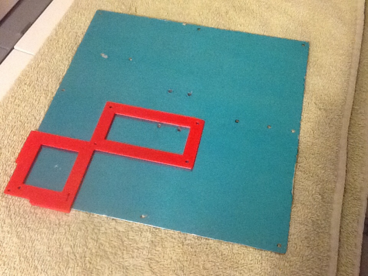
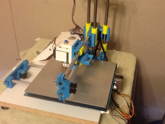
I bought 3/4"x11 3/4"x48" Melamine Shelf board from Home Depot for $7. They cut it into 12" lengths for free (should have been $0.50 a cut after two cuts).
I ended up buying K&S Rods and tubes for this build. 83033 Aluminum tubes for X and Y again and 87143 Stainless rods for the Z.
They are reasonably priced and can be found at hobby shops and online of course.
I'm using printed PLA bearings this time around. They are kinda tight at the moment. I'll have to work them a bit to free them up.
You print out a paper drill guide. Tape it together, and tape it to the board. Drill the holes with a 3mm bit.
Since I'm using a 3/4" thick board, I back drilled the backside with a 6.5mm drill bit about halfway through the board.
Assembly went together pretty easy. (well other than having the Z carriage flipped. lol) If it's your first build, then watch Cliffs assembly videos. They are well done, and explain everything clearly.
(I actually extended the Y axis on this build by using a straight edge to draw a line through the center of the drill guides holes to the end of each board. then measuring to get alignment. then drilling the new holes.) Hopefully pick up a bit more Y travel.
So far BOM listed above has been correct except for I missed the Y rods mounting screws. So add x4 M3x16mm screws/nuts/washers.
|
Re: Madmike8's Funbot build #2 April 29, 2015 01:22AM |
Registered: 10 years ago Posts: 814 |
|
Re: Madmike8's Funbot build #2 April 29, 2015 01:53PM |
Registered: 9 years ago Posts: 178 |
|
Re: Madmike8's Funbot build #2 May 06, 2015 06:08AM |
Registered: 10 years ago Posts: 148 |
|
Re: Madmike8's Funbot build #2 May 06, 2015 11:36AM |
Registered: 10 years ago Posts: 814 |
Make sure to send me a link when you have something to show.
Funbot#1 has been running pretty steady at work these days. Trouble free so far. No hardware adjustments after the first bed leveling. My coworkers are loving it. It's on it's third roll of filament already. When it's free, I've been printing Tslot Tantillus parts on it. So, I'd definitely be interested in the smaller footprint idea... For anyone interested the X/Y Aluminum Tubes have been working great.
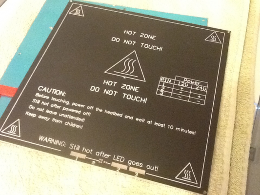
I was making some progress on wiring #2, but my soldering iron bit the dust. I ordered a larger one to help with soldering the MK3 Heatbed.
I did get the M8 threaded rod cut and installed.
My Ordbot is at the same spot. Awaiting rewiring...
I sent Buk his parts, but I think he was waiting on some parts to start his build.
|
Re: Madmike8's Funbot build #2 May 07, 2015 07:03AM |
Registered: 9 years ago Posts: 107 |
The PLA bearings are intriguing. I wonder if you can print nylon ones with lower friction and longer working life. There's lots of design that could make these bushings more feasible for reprap - e.g adjustable and quickly replaceable with minimum disassembly of the printer. Does anyone have any idea of lifespan?
|
Re: Madmike8's Funbot build #2 May 07, 2015 10:29AM |
Registered: 10 years ago Posts: 814 |
This is my first time using PLA Bearings, so I'm not sure on the wear characteristics. But I figured I'd give it a try. If I don't like them I'll replace them when the Bronze Bushings I used on Funbot#1. Sublime used them on his Tantillus, and I followed his directions on use. I used the sharp edge of the rods to cut/clean the bearing path by pressing on and removing the bearings a few times till it slid on the rod well. Then used a lite coat petroleum jelly on the rods to lube them.
Here's the one I use. I like that it uses OpenSCAD so I can adjust it how I need to.
PLA Linear ball bearing Thingverse Link
Here's the one I use. I like that it uses OpenSCAD so I can adjust it how I need to.
PLA Linear ball bearing Thingverse Link
|
Re: Madmike8's Funbot build #2 May 07, 2015 02:07PM |
Registered: 9 years ago Posts: 178 |
|
Re: Madmike8's Funbot build #2 May 07, 2015 05:33PM |
Registered: 9 years ago Posts: 107 |
|
Re: Madmike8's Funbot build #2 May 08, 2015 02:38AM |
Registered: 10 years ago Posts: 814 |
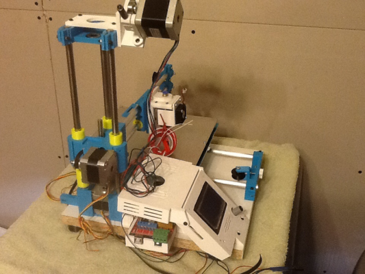
I got my new soldering iron in, so I started wiring.
Soldered ends on stepper motors
Replaced Heatbed MOSFET on the RAMPS board with IRLB8743
Soldered and assembled endstops.
Soldered Heatbed Wires.
Added hotend fan wiring and Bowden tube.
Put connectors on hotend/heatbed thermistors.
I need to clean up the wiring a bit more and adjust stepper drivers next.
|
Re: Madmike8's Funbot build #2 May 08, 2015 10:16AM |
Registered: 9 years ago Posts: 156 |
|
Re: Madmike8's Funbot build #2 May 08, 2015 10:21AM |
Registered: 9 years ago Posts: 178 |
|
Re: Madmike8's Funbot build #2 May 08, 2015 10:46AM |
Registered: 10 years ago Posts: 814 |
As usual, I'm following the work of others ahead of me. Since my newer builds have been using a heated beds, I wanted to make sure to alleviate any problems ahead of time... They are pretty cheap, so I thought I'd give them a try. I might add a heatsink too.
Quote
Cefiar
The FET on most RAMPS boards is a STP55NF06L, though I would personally replace it with something different like an FDP8870 or (and the one I like most at the moment) the IRLB8743.
The advantages of both of these FETs is that they have a MUCH lower Rds(on) than the original (this means they dissipate less heat when switched "on"), are pin compatible, and are about the same cost. The IRLB8743 has the lowest Rds(on) value, but both it and the FDP8870's work well for driving the heated bed.
Note: The IRLB8743 only supports up to 30V, however this should not be an issue if you're only running 12V or 24V. I've not seen anyone use >24V for the heated bed through the FET, so I generally consider this to be a non-issue, but I know some people are looking at 36V for their motors, so I thought it best to mention it in passing.
PS: If you're going to remove the FET, I recommend cutting the existing FET off (just under the plastic body) then desoldering the pins individually with a decent temp controllable iron that can put out a decent power and a pair of needle-nose pliers. Once you've removed that, you can use solder wick and a solder sucker to clean up the pads/holes. One of the pins on the FET (the source) is connected to ground. As the ground plane on the PCB is quite large, it requires a bit of heat and power to properly remove the FET pin and then clean the pad/hole. Trying to heat all 3 pads on the PCB at once (so you can remove the FET without cutting it's leads) is not easy, especially when one of them requires more power/heat to remove.
Sorry, only registered users may post in this forum.
