Another Smart Rap Core build
Posted by Zlob
|
Re: Another Smart Rap Core build June 04, 2015 09:40AM |
Registered: 8 years ago Posts: 65 |
Duranza:
so wich kind of pulley ? I thought i got a 20 teeth, i need a 36 one ?
SmartFriendz:
If I print the new support, i need to print motor and bearing support or just bearig support ?
About switches, are the new position already into jscad software ?
BTW, you sell the pulley ??? pvt me !
Thanks all.
so wich kind of pulley ? I thought i got a 20 teeth, i need a 36 one ?
SmartFriendz:
If I print the new support, i need to print motor and bearing support or just bearig support ?
About switches, are the new position already into jscad software ?
BTW, you sell the pulley ??? pvt me !
Thanks all.
|
Re: Another Smart Rap Core build June 04, 2015 11:51AM |
Registered: 9 years ago Posts: 156 |
The one RcJoseb is using looks like it gives good clearance. Looking at the bearing supports, can you try and see if you can switch the parts around? Like the right to the left and the left to the right? I don't know if there would be enough space to to that, but if there is, this will move the bearings out more to give clearance.
|
Re: Another Smart Rap Core build June 04, 2015 11:57AM |
Registered: 9 years ago Posts: 156 |
|
Re: Another Smart Rap Core build June 04, 2015 12:49PM |
Registered: 9 years ago Posts: 180 |
|
Re: Another Smart Rap Core build June 04, 2015 01:36PM |
Registered: 8 years ago Posts: 65 |
Hi rcjoseb!
For what i know, the bearings ARE 608ZZ (as listed on ebay auction ); Not sure 100% for the pulley, i had to ask.
About the center, well i think that maybe there is an error into jscad file ?
I have used the 1.0.1 version with 8 mm rod for x & y and 17 mm for wood thickness and 10 mm for Z axis.
Can someone confirm that with those parameter the generated piece plate are ok ?
I mean all the center look ok, but the other distance ?
Or, someone have already made a printer with 8 mm x-y rod ?
thanks all !
For what i know, the bearings ARE 608ZZ (as listed on ebay auction
); Not sure 100% for the pulley, i had to ask.About the center, well i think that maybe there is an error into jscad file ?
I have used the 1.0.1 version with 8 mm rod for x & y and 17 mm for wood thickness and 10 mm for Z axis.
Can someone confirm that with those parameter the generated piece plate are ok ?
I mean all the center look ok, but the other distance ?
Or, someone have already made a printer with 8 mm x-y rod ?
thanks all !
|
Re: Another Smart Rap Core build June 04, 2015 02:40PM |
Registered: 9 years ago Posts: 180 |
For the pulley, mark one tooth (ridge) with a marker then count all if them. It shoudl be a total of 20 teeth (ridges).
It's simple to check for the bearing mount. Start at a point close to the motor and measure the distance from the edge of the rod to the inside wall of the box. Then repeat the measurement closest to the bearing mount. They shoould be the same. If the rear is closer to the inside wall of the box, then adjust the rear bearing mount towards the center of the box and visa versa if it's farther away at the bearing mount. Do the same for the other side. This ensures the rods are parallel.
It's simple to check for the bearing mount. Start at a point close to the motor and measure the distance from the edge of the rod to the inside wall of the box. Then repeat the measurement closest to the bearing mount. They shoould be the same. If the rear is closer to the inside wall of the box, then adjust the rear bearing mount towards the center of the box and visa versa if it's farther away at the bearing mount. Do the same for the other side. This ensures the rods are parallel.
|
Re: Another Smart Rap Core build June 06, 2015 02:47AM |
Registered: 8 years ago Posts: 65 |
Back again.
After a full dismount of the printer, i started re-build agin.
I use the motor support, with a little piece of steel rod to fix at the correct position the bearing holder.
In this way i'm sure that the distance betwen the motor support and bearing support are correct.
(Hope you understand, i will try to get a better explanation later!)
Also rebuild the whole x carriage.
This time the belt aren't touching, and all look move smoothly.
I will test motor and connection soon.
Wich firmware u prefer ? Someone choose MARLIN, other pplchoose REPETIER ...
Don't know wich choose ...
Thanks as usually
|
Re: Another Smart Rap Core build June 07, 2015 05:36PM |
Registered: 9 years ago Posts: 107 |
|
Re: Another Smart Rap Core build June 08, 2015 12:11PM |
Registered: 8 years ago Posts: 65 |
Hi all.
This time the questions are two and the stop will be longer.
Yesterday i burn the MEGA and i'm looking to buy a new one.
I try to repair (look like the voltage regulator was burn so change with a 7805) and works partially: it run and drive motor butisn't possible to connect with REPETIER nor programming again.
So, jump to question:
- where put the dimension into MARLIN soft ? I project the print volume for 250x250x250. Where put this value ?
(find on the net the rcjoseb pdf for smartrap. I bet i can adapt it)
- As i use that dimension into jscad soft, i buy a 270x270 piece of wood to use as table and a piece of glass about 250x250.
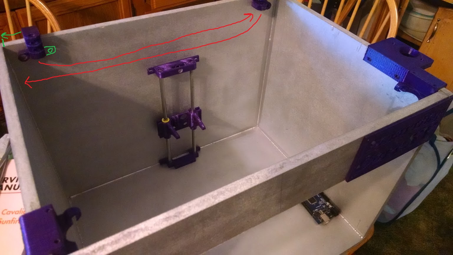
When i issue the home command, both extrusor and proxymity sensor goes out of the table. This make the Z axis NEVER go home as the proxymity sensor can't sense the table. I must buy a bigger table or is software issue ?
While wait for the postman give me a new mega, thanks for your help !
Addendum:
I take two pict:
The metal is just alluminium sheet, the one u use into kitchen (yes, the sensor detect it).
HOpe is more clear what I mean.
Edited 3 time(s). Last edit at 06/08/2015 03:44PM by Zlob.
This time the questions are two and the stop will be longer.
Yesterday i burn the MEGA and i'm looking to buy a new one.
I try to repair (look like the voltage regulator was burn so change with a 7805) and works partially: it run and drive motor butisn't possible to connect with REPETIER nor programming again.
So, jump to question:
- where put the dimension into MARLIN soft ? I project the print volume for 250x250x250. Where put this value ?
(find on the net the rcjoseb pdf for smartrap. I bet i can adapt it)
- As i use that dimension into jscad soft, i buy a 270x270 piece of wood to use as table and a piece of glass about 250x250.
When i issue the home command, both extrusor and proxymity sensor goes out of the table. This make the Z axis NEVER go home as the proxymity sensor can't sense the table. I must buy a bigger table or is software issue ?
While wait for the postman give me a new mega, thanks for your help !
Addendum:
I take two pict:


The metal is just alluminium sheet, the one u use into kitchen (yes, the sensor detect it).
HOpe is more clear what I mean.
Edited 3 time(s). Last edit at 06/08/2015 03:44PM by Zlob.
|
Re: Another Smart Rap Core build June 08, 2015 04:08PM |
Registered: 9 years ago Posts: 107 |
Look at this section of configuration.h for the print volume dimensions:
Then look at this section for safe z homing (enable this) which puts the print head in the centre of the print area before z homing:
For the difference between the 0,0,0 coordinates and the heated bed corner, I set this up in the printer settings in repetier host.
I use G28 and G29 custom gcode at the start of a print (home all axes and autolevel).
Edited 1 time(s). Last edit at 06/08/2015 04:15PM by smerrett79.
//Travel limits after homing (units are in mm)
#define X_MIN_POS 0
#define Y_MIN_POS 0
#define Z_MIN_POS 0
#define X_MAX_POS 200
#define Y_MAX_POS 200
#define Z_MAX_POS 180
Then look at this section for safe z homing (enable this) which puts the print head in the centre of the print area before z homing:
//If you have enabled the Bed Auto Leveling and are using the same Z Probe for Z Homing,
//it is highly recommended you let this Z_SAFE_HOMING enabled!!!

  #define Z_SAFE_HOMING   // This feature is meant to avoid Z homing with probe outside the bed area.
                          // When defined, it will:
                          // - Allow Z homing only after X and Y homing AND stepper drivers still enabled
                          // - If stepper drivers timeout, it will need X and Y homing again before Z homing
                          // - Position the probe in a defined XY point before Z Homing when homing all axis (G28)
                          // - Block Z homing only when the probe is outside bed area.

  #ifdef Z_SAFE_HOMING

    #define Z_SAFE_HOMING_X_POINT (X_MAX_LENGTH/2)    // X point for Z homing when homing all axis (G28)
    #define Z_SAFE_HOMING_Y_POINT (Y_MAX_LENGTH/2)    // Y point for Z homing when homing all axis (G28)

  #endif
For the difference between the 0,0,0 coordinates and the heated bed corner, I set this up in the printer settings in repetier host.
I use G28 and G29 custom gcode at the start of a print (home all axes and autolevel).
Edited 1 time(s). Last edit at 06/08/2015 04:15PM by smerrett79.
|
Re: Another Smart Rap Core build June 11, 2015 12:58PM |
Registered: 8 years ago Posts: 65 |
HI all.
The new Arduino mega is here and I restart working on the printer.
I still have an electronic issue woth proxymity sensor, but i can manage it (using 7805 send just 1,5V to signal pin).
The "big" trouble is the software.
I try the MARLIN one, got from github and modified just for the display BUT having trouble.
I try the REPETIER one, configured as rcjoseb share into the "SmartRapCore dual Z axis with 2 motors issue" pos but having trouble too.
The trouble are those:
- selecting autohome from display:
- MARLIN need the motor reverse or goes to the wrong angle: i have the old switch setting so home is left-front, but the soft push the printer head to back-right!
- REPETIER correctly home the X and Y axis but Z can't never homed as the sensor is out of table (look the picture above).
Also i have really slow speed onto homing, expecially on Z.
Can someone point me to a correct software version (or send me the config.h file) for a smartrap core with a printable area of 250x250x250 ?
Thanks
|
Re: Another Smart Rap Core build June 15, 2015 06:29AM |
Registered: 9 years ago Posts: 26 |
|
Re: Another Smart Rap Core build June 15, 2015 07:39AM |
Registered: 8 years ago Posts: 65 |
Hi s0me.
My motor mount are tight enought.
(If need a close image to be sure, i will post)
The only little trouble i had was about the wood thickness.
I bought 16mm MDF, but i must say to JSCAD that i had 17mm wall otherwise i can't fit the motor mount into wood.
Now I'm *still* stuck with firmware.
With the smartrap core original i must invert all the motor connection but still can't get nothing good.
With RCJoseb repetier flawour firmware, i can get it moving, and somehow print (completely wrong, anyway!).
Look like measurement are all wrong.
The worst issue is still the Z axis: today i discovered that my plate is too thin so i must add something to get plate more thick otherwise the hotend will be too far from plate (the motor try to raise the plate but belt skip as the plate is at his mechanical top).
Still having the X0 Y0 issue: if i home the xy axis, the proxymity sensor can't get engaged by plate as the plate is shorter; same as I issue a G29 command to autolevel the Z axs: if i start into xy home position can't zeroes.
I try to add to startup code somthing like this:
G28 X0 Y0 // Home XY
G1 X30 Y30 //Move xy TO 30,30
G29 // Autolevel and this time can sense the plate
Also today i discovered that my print volume is really bigger than i want: i put 250 for XYZ into JSCAD but the effective travel lenght for X and Y are around 400 mm !!!
News: the movement aren't correct.
I draw a square 100*100*100 with sketchup and try to print.
No matter what i change into repetier software, it comes 50*50.
Look like the printer divide the size by 2 as default.
I try to put 80 (standard), 40 and 20 step*mm but no change.
Of course i recompile and send firmware to arduino every time ...
Need a coffe and a break.
Try again later.
Can someone help me ???
Edited 2 time(s). Last edit at 06/15/2015 10:00AM by Zlob.
My motor mount are tight enought.
(If need a close image to be sure, i will post)
The only little trouble i had was about the wood thickness.
I bought 16mm MDF, but i must say to JSCAD that i had 17mm wall otherwise i can't fit the motor mount into wood.
Now I'm *still* stuck with firmware.
With the smartrap core original i must invert all the motor connection but still can't get nothing good.
With RCJoseb repetier flawour firmware, i can get it moving, and somehow print (completely wrong, anyway!).
Look like measurement are all wrong.
The worst issue is still the Z axis: today i discovered that my plate is too thin so i must add something to get plate more thick otherwise the hotend will be too far from plate (the motor try to raise the plate but belt skip as the plate is at his mechanical top).
Still having the X0 Y0 issue: if i home the xy axis, the proxymity sensor can't get engaged by plate as the plate is shorter; same as I issue a G29 command to autolevel the Z axs: if i start into xy home position can't zeroes.
I try to add to startup code somthing like this:
G28 X0 Y0 // Home XY
G1 X30 Y30 //Move xy TO 30,30
G29 // Autolevel and this time can sense the plate
News: the movement aren't correct.
I draw a square 100*100*100 with sketchup and try to print.
No matter what i change into repetier software, it comes 50*50.
Look like the printer divide the size by 2 as default.
I try to put 80 (standard), 40 and 20 step*mm but no change.
Of course i recompile and send firmware to arduino every time ...
Need a coffe and a break.
Try again later.
Can someone help me ???
Edited 2 time(s). Last edit at 06/15/2015 10:00AM by Zlob.
|
Re: Another Smart Rap Core build June 15, 2015 10:45AM |
Registered: 9 years ago Posts: 180 |
Ziob, I can create a custom configuration.h file for you. Lets start with the Marlin firmware to get you going as it's easiert to understand. Please let me knoe the folowing:
1. The size of the print bed that you are printing on
2. The type of inductive sensor, is it an NPN NO?
3. Type of endstops, mechanical or electronic. The electronic ones have a little circuit board attached to them.
I will assume you are using a RAMPS V1.3/V1.4, an epcos 100k thermistor and non xbox power supply.
Edited 1 time(s). Last edit at 06/15/2015 10:47AM by rcjoseb.
|
Re: Another Smart Rap Core build June 15, 2015 10:54AM |
Registered: 10 years ago Posts: 814 |
|
Re: Another Smart Rap Core build June 15, 2015 12:47PM |
Registered: 8 years ago Posts: 65 |
@madmike8: have a RAMPS 1.4 board with 4988 driver, all jumper are onto RAMPS, so I assume that i'm using 16 microstep.
After the calculation needed (200*16)/(2*20) the result is 80 but something is wrong ...
I have already the 8825 driver, but they are still untouched into theirs bags.
rcjoseb, thanks.
The print area on wich i build the printer is 250x250x250 millimeters.
The sensor is a LJ12A3-4-Z/BX - Normally Open NPN proxymity sensor
The endstops ARE mechanicals, Normally Closed (external point connected to Signal and ground pins on RAMPS).
Belt is GT2 and pulley are 20T.
HotEnd is an JHEAD with NTC, no idea wich is, i guess the one u say, at least it works (heat up and temperature is show).
I will use your config to see if it works and look what and where u change something !!!
Thanks.
Edited 1 time(s). Last edit at 06/15/2015 01:17PM by Zlob.
|
Re: Another Smart Rap Core build June 15, 2015 01:20PM |
Registered: 9 years ago Posts: 180 |
Here is the configuration.h You will want to watch out for a couple of settings and check them. To make it eadier, I have made them BOLD and ITALIC.
#ifndef CONFIGURATION_H
#define CONFIGURATION_H
// This is a customized version of the Configuration.h file for the SmartRapCore.
// Customized by Jose a.k.a. RCJOSEB on 6/9/2015.
// USE THE EEPROM TO SAVE SETTINGS
#define EEPROM_SETTINGS
#define EEPROM_CHITCHAT
// SET THE PRINTER TYPE AND SIZE
#define COREXY
#define X_MIN_POS 0
#define Y_MIN_POS 0
#define Z_MIN_POS 0
#define X_MAX_POS 250
#define Y_MAX_POS 250
#define Z_MAX_POS 250
#define X_MAX_LENGTH (X_MAX_POS - X_MIN_POS)
#define Y_MAX_LENGTH (Y_MAX_POS - Y_MIN_POS)
#define Z_MAX_LENGTH (Z_MAX_POS - Z_MIN_POS)
// SET THE MOTHERBOARD TYPE, COMMUNICATIONS AND POWER SUPPLY
#define MOTHERBOARD 33
#define SERIAL_PORT 0
#define BAUDRATE 250000
#define POWER_SUPPLY 1
// SET THE DISPLAY INFO FOR PRONTERFACE OR SIMILAR APPLICATION
#define STRING_VERSION_CONFIG_H __DATE__ " " __TIME__
#define STRING_CONFIG_H_AUTHOR "(none, default config)"
// SET THE HOTENDS A.K.A EXTRUDERS
#define EXTRUDERS 1
#define PREVENT_LENGTHY_EXTRUDE
#define EXTRUDE_MINTEMP 170
#define EXTRUDE_MAXLENGTH (X_MAX_LENGTH+Y_MAX_LENGTH) //prevent extrusion of very large distances.
#define PLA_PREHEAT_HOTEND_TEMP 210
#define PLA_PREHEAT_FAN_SPEED 255
// SET THE TEMPERATURE SENSORS
#define TEMP_SENSOR_0 1
#define TEMP_RESIDENCY_TIME 10
#define TEMP_HYSTERESIS 3
#define TEMP_WINDOW 1
#define HEATER_0_MINTEMP 5
#define HEATER_0_MAXTEMP 275
// SET THE PID TEMPERATURE CONTROL
#define PIDTEMP
#define BANG_MAX 255
#define PID_MAX 255
#define PID_FUNCTIONAL_RANGE 10
#define PID_INTEGRAL_DRIVE_MAX 255
#define K1 0.95
#define PID_dT ((OVERSAMPLENR * 10.0)/(F_CPU / 64.0 / 256.0))
#define DEFAULT_Kp 22.2
#define DEFAULT_Ki 1.08
#define DEFAULT_Kd 114
// SET THE ENDSTOPS
// The inductive sensor used is an NPN NO which when triggers produces 0 volts.
// When triggered, the status in Pronterface will still indicate open.
#define ENDSTOPPULLUPS
#define ENDSTOPPULLUP_XMAX
#define ENDSTOPPULLUP_YMAX
#define ENDSTOPPULLUP_ZMAX
#define ENDSTOPPULLUP_XMIN
#define ENDSTOPPULLUP_YMIN
#define ENDSTOPPULLUP_ZMIN
const bool X_MIN_ENDSTOP_INVERTING = false;
const bool Y_MIN_ENDSTOP_INVERTING = false;
const bool Z_MIN_ENDSTOP_INVERTING = true;
const bool X_MAX_ENDSTOP_INVERTING = true;
const bool Y_MAX_ENDSTOP_INVERTING = true;
const bool Z_MAX_ENDSTOP_INVERTING = true;
#if defined(COREXY) && !defined(DISABLE_MAX_ENDSTOPS)
#define DISABLE_MAX_ENDSTOPS
#endif
#define min_software_endstops false
#define max_software_endstops false
// SET THE MOTOR AXIS
#define X_ENABLE_ON 0
#define Y_ENABLE_ON 0
#define Z_ENABLE_ON 0
#define E_ENABLE_ON 0
#define DISABLE_X false
#define DISABLE_Y false
#define DISABLE_Z false
#define DISABLE_E false
#define DISABLE_INACTIVE_EXTRUDER true
#define INVERT_X_DIR true
#define INVERT_Y_DIR true
#define INVERT_Z_DIR false
#define INVERT_E0_DIR true
#define INVERT_E1_DIR false
#define INVERT_E2_DIR false
#define X_HOME_DIR -1
#define Y_HOME_DIR -1
#define Z_HOME_DIR -1
#define MANUAL_X_HOME_POS 0
#define MANUAL_Y_HOME_POS 0
#define MANUAL_Z_HOME_POS 0
#define NUM_AXIS 4
#define HOMING_FEEDRATE {70*60, 70*60, 2*60, 0}
#define DEFAULT_AXIS_STEPS_PER_UNIT {80,80,80,85}
#define DEFAULT_MAX_FEEDRATE {500, 500, 2, 50}
#define DEFAULT_MAX_ACCELERATION {6000,6000,100,10000}
#define DEFAULT_ACCELERATION 3000
#define DEFAULT_RETRACT_ACCELERATION 3000
// SET AUTO BED LEVELING GRID
#define ENABLE_AUTO_BED_LEVELING
#define Z_PROBE_REPEATABILITY_TEST
#define AUTO_BED_LEVELING_GRID
#define LEFT_PROBE_BED_POSITION 50
#define RIGHT_PROBE_BED_POSITION 180
#define BACK_PROBE_BED_POSITION 180
#define FRONT_PROBE_BED_POSITION 50
#define AUTO_BED_LEVELING_GRID_POINTS 3
#define X_PROBE_OFFSET_FROM_EXTRUDER 0
#define Y_PROBE_OFFSET_FROM_EXTRUDER 0
#define Z_PROBE_OFFSET_FROM_EXTRUDER 0
#define Z_RAISE_BEFORE_HOMING 4
#define XY_TRAVEL_SPEED 3000
#define Z_RAISE_BEFORE_PROBING 15
#define Z_RAISE_BETWEEN_PROBINGS 10
#define Z_SAFE_HOMING
#define Z_SAFE_HOMING_X_POINT (X_MAX_LENGTH/2)
#define Z_SAFE_HOMING_Y_POINT (Y_MAX_LENGTH/2)
#define DEFAULT_XYJERK 20.0
#define DEFAULT_ZJERK 10.0
#define DEFAULT_EJERK 5.0
#define ABS_PREHEAT_HOTEND_TEMP 240
#define ABS_PREHEAT_HPB_TEMP 100
#define ABS_PREHEAT_FAN_SPEED 255
// ADDITIONAL M CODEs
#define CUSTOM_M_CODES
#define CUSTOM_M_CODE_SET_Z_PROBE_OFFSET 851
#define Z_PROBE_OFFSET_RANGE_MIN -5
#define Z_PROBE_OFFSET_RANGE_MAX 0
// LCD
#define REPRAP_DISCOUNT_FULL_GRAPHIC_SMART_CONTROLLER
#define U8GLIB_ST7920
#define REPRAP_DISCOUNT_SMART_CONTROLLER
#define ULTIPANEL
#define NEWPANEL
#define DOGLCD
#define ULTRA_LCD
#define SDSUPPORT
#define SD_CHECK_AND_RETRY
#define ENCODER_PULSES_PER_STEP 1
#define ENCODER_STEPS_PER_MENU_ITEM 5
#define LCD_FEEDBACK_FREQUENCY_HZ 1000
#define LCD_FEEDBACK_FREQUENCY_DURATION_MS 100
#define LCD_WIDTH 20
#define LCD_HEIGHT 5
#define DEFAULT_LCD_CONTRAST 32
#define SOFT_PWM_SCALE 0
// THESE SETTINGS ARE NOT USED IN THIS BUILD BUT ARE BEING CALLED BY OTHER CODE SECTIONS
#define PLA_PREHEAT_HPB_TEMP 0
#define MAX_BED_POWER 0
// THESE SETTINGS ARE NOT USED IN THIS BUILD AND ARE BEING CALLED BY OTHER CODE SECTIONS
// #define TEMP_SENSOR_1 0
// #define TEMP_SENSOR_2 0
// #define TEMP_SENSOR_BED 0
// #define MAX_REDUNDANT_TEMP_SENSOR_DIFF 10
// #define HEATER_1_MINTEMP 5
// #define HEATER_2_MINTEMP 5
// #define BED_MINTEMP 5
// #define HEATER_1_MAXTEMP 275
// #define HEATER_2_MAXTEMP 275
// #define BED_MAXTEMP 150
// #define DISABLE_MIN_ENDSTOPS
#include "Configuration_adv.h"
#include "thermistortables.h"
#endif //__CONFIGURATION_H
|
Re: Another Smart Rap Core build June 15, 2015 04:41PM |
Registered: 8 years ago Posts: 65 |
Some news...
Uploading the new config dosn't change almost anything.
I try to measure waht the printer do and ... well, if i issue a G1 X50 command, the X axis move for 25 mm.
So, i try to double the step value to 160 instead 80.
And the printer move correctly.
Now i'm investigating where I made mistake: driver are 4988, setting are for 1/16, motor are labelled for 1,8°/step ... Wich one is the liar ???
Thanks all for your support ...
Meanwhile i burn another Arduino 2560 ... *grin*
Edited 1 time(s). Last edit at 06/15/2015 04:41PM by Zlob.
|
Re: Another Smart Rap Core build June 15, 2015 06:45PM |
Registered: 8 years ago Posts: 6 |
|
Re: Another Smart Rap Core build June 16, 2015 04:57AM |
Registered: 8 years ago Posts: 65 |
@dkulinski: i'm not sure at all.
I'm checking all the stuff to find the mistake.
The pulley are 20T for sure, as i generate it with a thingiverse generator and printed them. Again, i have count the teeth and they are 20.
Driver are 4988 for sure: i read (with a big lens !) the value directly from the chip.
Ramps and Mega are ok, the software is now the repetier one as ican change on the fly some eeprom settings (eg. 80->160).
The motors are listed as 1,8°/step. I wrote to the seller and they told me that into euro-warehouse they don't have ANY 0,9°/step.
In a while i go to measure the pitch of the GT2 belt. Maybe the trik is there.
Any suggestion to how check if motor is a 1,8°/step or a 0,9°/step one ?
(I thought to use an arduino UNO R3, connected to the DRIVER without any jumper and send 200 impulse to see if it does a complete turns...)
Thanks all
I'm checking all the stuff to find the mistake.
The pulley are 20T for sure, as i generate it with a thingiverse generator and printed them. Again, i have count the teeth and they are 20.
Driver are 4988 for sure: i read (with a big lens
!) the value directly from the chip.Ramps and Mega are ok, the software is now the repetier one as ican change on the fly some eeprom settings (eg. 80->160).
The motors are listed as 1,8°/step. I wrote to the seller and they told me that into euro-warehouse they don't have ANY 0,9°/step.
In a while i go to measure the pitch of the GT2 belt. Maybe the trik is there.
Any suggestion to how check if motor is a 1,8°/step or a 0,9°/step one ?
(I thought to use an arduino UNO R3, connected to the DRIVER without any jumper and send 200 impulse to see if it does a complete turns...)
Thanks all
|
Re: Another Smart Rap Core build June 16, 2015 07:05AM |
Registered: 8 years ago Posts: 65 |
My hardware is right.
The answer is here: [forum.repetier.com]
On the first answer Mr. Repetier say that on corexy u must multiply *2 the calculated step*mm.
And i got 80 step*mm but i need to put 160 ...
I'm still surprised that no one got same trouble as me ...
*** NEWS ***
The effective print volume isn't as expected.
I put 250x250x250 into jscad generator expecting an effective volume of 250x250x250, but the effective volume is around 210x210x(NOT TESTED).
That's an important issue as i need the volume i project and the only way to get it is REBUILD the box and buy new rod.
Edited 1 time(s). Last edit at 06/16/2015 07:25AM by Zlob.
- MicroStep is 1/16 as driver is4988
- Stpper motors are 1,8°/step
- Belt is GT2
- Pulley are 20T
The answer is here: [forum.repetier.com]
On the first answer Mr. Repetier say that on corexy u must multiply *2 the calculated step*mm.
And i got 80 step*mm but i need to put 160 ...
I'm still surprised that no one got same trouble as me ...
*** NEWS ***
The effective print volume isn't as expected.
I put 250x250x250 into jscad generator expecting an effective volume of 250x250x250, but the effective volume is around 210x210x(NOT TESTED).
That's an important issue as i need the volume i project and the only way to get it is REBUILD the box and buy new rod.
Edited 1 time(s). Last edit at 06/16/2015 07:25AM by Zlob.
|
Re: Another Smart Rap Core build June 16, 2015 09:49AM |
Registered: 10 years ago Posts: 814 |
|
Re: Another Smart Rap Core build June 16, 2015 05:56PM |
Registered: 10 years ago Posts: 992 |
that's strange with the build volume ? Normally, if you enter 250x250x250 in the print size, you will go for 315 mm X rod size, for example and that should give you around 250mm printable on X ( with a 250 wide plate of course ).
I will check again though..
the Smartrap project
[smartfriendz.com]
[www.thingiverse.com]
[reprap.org]
[github.com]
doc assemblage: [reprap.org]
NEW: Forum smartfriendz: [smartraptalk.smartfriendz.com]
I will check again though..
the Smartrap project
[smartfriendz.com]
[www.thingiverse.com]
[reprap.org]
[github.com]
doc assemblage: [reprap.org]
NEW: Forum smartfriendz: [smartraptalk.smartfriendz.com]
|
Re: Another Smart Rap Core build June 17, 2015 04:30AM |
Registered: 8 years ago Posts: 65 |
Quote
smartfriendz
that's strange with the build volume ? Normally, if you enter 250x250x250 in the print size, you will go for 315 mm X rod size, for example and that should give you around 250mm printable on X ( with a 250 wide plate of course ).
I will check again though..
Well, just re-generate with JSCAD, version "1.0.8 mar 2015" with these parameters:
X,Y,Z = 250
wood thikness = 17
xrod = 8
yrod = 8
zrod = 10
and the X rod isn't 315 but 305. The 315 is the Y rod ...
I attach a picture to show.

I have checked the print volume and is around 220x220x but you really go near to mech limit.
edit: sorry, i forgot to mention that I use the ycarriage and head from version 1.2 old style endstops.
Maybe the original head is smaller ?
Edited 3 time(s). Last edit at 06/17/2015 08:08AM by Zlob.
|
Re: Another Smart Rap Core build June 17, 2015 08:40AM |
Registered: 8 years ago Posts: 65 |
|
Re: Another Smart Rap Core build June 17, 2015 10:05AM |
Registered: 9 years ago Posts: 180 |
"The answer is here: [forum.repetier.com]
On the first answer Mr. Repetier say that on corexy u must multiply *2 the calculated step*mm.
And i got 80 step*mm but i need to put 160 ...
I'm still surprised that no one got same trouble as me ..."
OMG!!!! Jerry and I were just discussing this this weekend on the facebook group. I have the same exact issue with Repetier and so did Jerry. With Marlin, the print bed size in mm where the hot end can actually print is 260 X 270 but in Repetier it's 411 x 411. I too have DRV8825 steppers with 1.8 degree motors and stepping set to 1/16. Jerry said he had the same issue and was able to resolve it by re-flashing/setting the firmware a couple of times. It did not work for me whatever I did.
Thanks for the answer to the problem, Ziob!!!!!
|
Re: Another Smart Rap Core build June 17, 2015 10:12AM |
Registered: 9 years ago Posts: 180 |
Tom has a great video on auto bed leveling but some of the things he says are a little confusing.
[www.youtube.com]
I found this great article on instructables and that is what I am going to follow.
[www.instructables.com]
The sensor, according to the article, should be about 4mm above the tip of the hot end but that depends on how well your sensor can pickup metal. I switched from using aluminum flashing to a galvanized steel sheet and the sensor can now sense much better. With the aluminum flashing, the sensor had to get really, really close.
I have the galvanized steel sheet, which is about 2/16 thin, glued to a piece of luan so that it's supported. To print, I am using painter's tape on the metal. I plan on placing a sheet of PEI on the metal so I can eliminate the tape altogether. I purhased the galvanized steel plate at home depot but I am sure you can find it at your local hardware store where you are. This is very important. The galvanized steel sheet must be magnetic. That's what triggers the sensor better than just plain metal.
|
Re: Another Smart Rap Core build June 17, 2015 10:47AM |
Registered: 9 years ago Posts: 95 |
Sorry for going a bit off-topic here but I fail to see the value of auto-leveling using a sensor... Been there, done that and came back...
I mean, once you *manually* level your bed once, there is really no reason for it to become non-level. Why have an auto-leveling process which tries to correct your non-level bed when you could just level it once and be done with it? Also, with auto-leveling enabled, your Z motor(s) will be constantly working throughout the print adding even more variables to the final print quality (e.g. backlash, microsteps accuracy, etc).
It's like having slightly punctured tires on your car, losing air pressure daily, and instead of getting them fixed (or changed), you prefer to have to inflate them each morning before you begin your day...
|
Re: Another Smart Rap Core build June 17, 2015 04:38PM |
Registered: 8 years ago Posts: 65 |
Quote
mandrav
I mean, once you *manually* level your bed once, there is really no reason for it to become non-level. Why have an auto-leveling process which tries to correct your non-level bed when you could just level it once and be done with it? Also, with auto-leveling enabled, your Z motor(s) will be constantly working throughout the print adding even more variables to the final print quality (e.g. backlash, microsteps accuracy, etc).
It's like having slightly punctured tires on your car, losing air pressure daily, and instead of getting them fixed (or changed), you prefer to have to inflate them each morning before you begin your day...
Well, i think you are partially right.
If u have a threth rod for z level, a full metal Z axis and sledge when u level the bed it still remain level.
But all meatl stuff is really expensive.
In my case, Z axis is full PLA, sledge is full PLA too and no thread rod but GT2 belt.
To the opposite side of Zaxis, bed will force down and go out of level. I do some test but still have the bed moving.
Today i bought a bigger bed (the first attemp was 270x270, this one is 320x330 and 0,8 thick wood) and hope it will be more stable.
Anyway, I think using the autolevel is a good idea for this kind of setup.
And yes, if can't afford the expenses for a new tire, until you get money you inflate them every day

|
Re: Another Smart Rap Core build June 26, 2015 04:02PM |
Registered: 8 years ago Posts: 65 |
Hi all.
After lot of test, with lot maerials i really need help with Z axis.
Today i reprint the z axis, and use the V 1.2 .
Still having some trouble: as i use 10 mm rod the sledge touch a little backward.
But the worst thing is which kind of plate i must use.
I look on the net and see that Serge use a little piece of wood with some kind of glass fixed on it;
someone ise larger wood with glass;
other wood+heated bed+glass and so on.
I have bought a 250x250 4mm thick wood but is a little shorter to 0 position.
I bought than a 330x320 8mm thick wood but it bend opposite to z-sledge fix
Can someone help me ?
Thanks.
PS: I have think to print the rod version for the Z axis. Where i can discover wich screw is used (M5 ? M6 ? M8?)


Sorry, only registered users may post in this forum.