Banding....
Posted by Billhc83
|
Banding.... January 13, 2016 06:14PM |
Registered: 8 years ago Posts: 22 |
Hi,
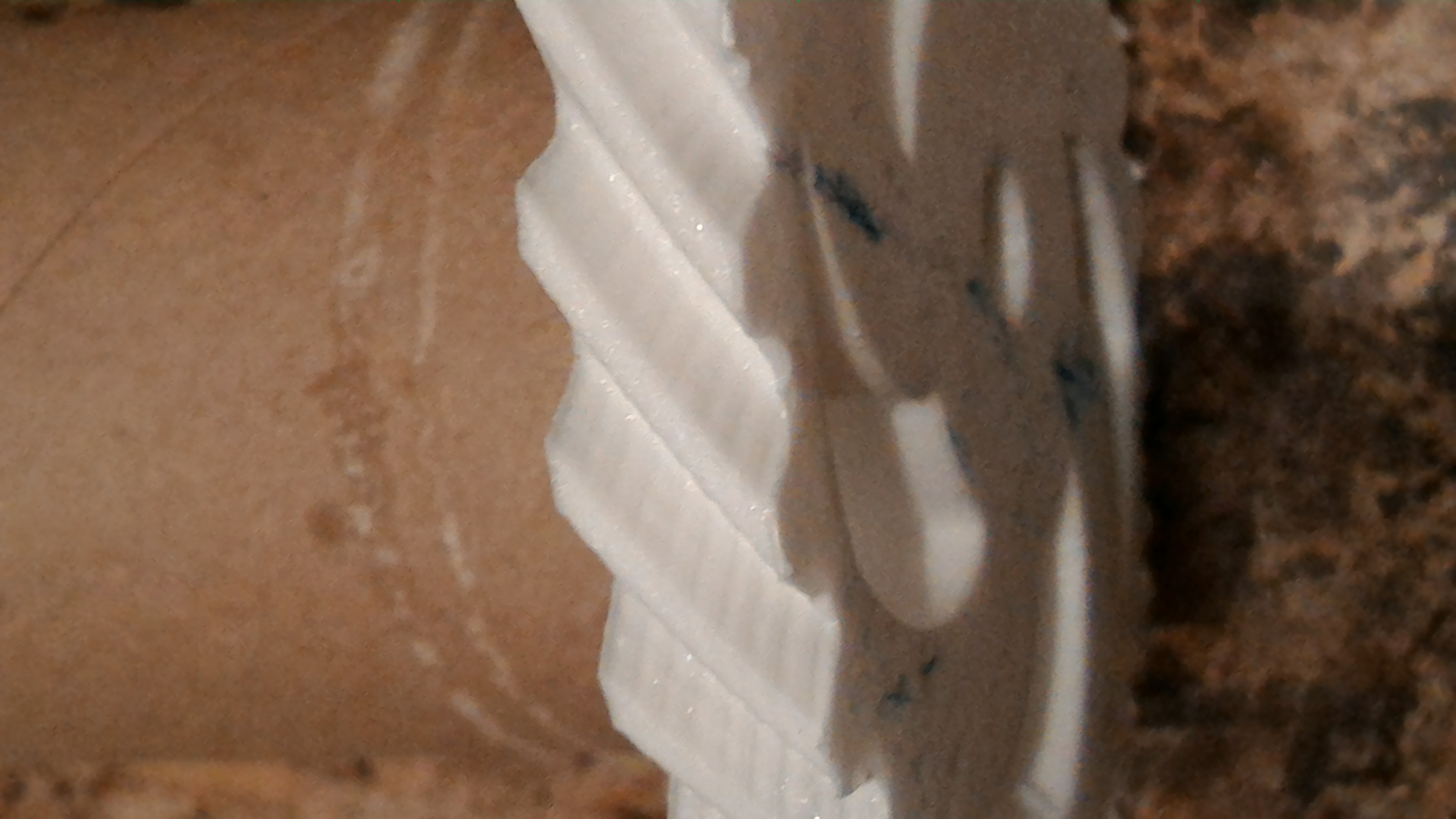
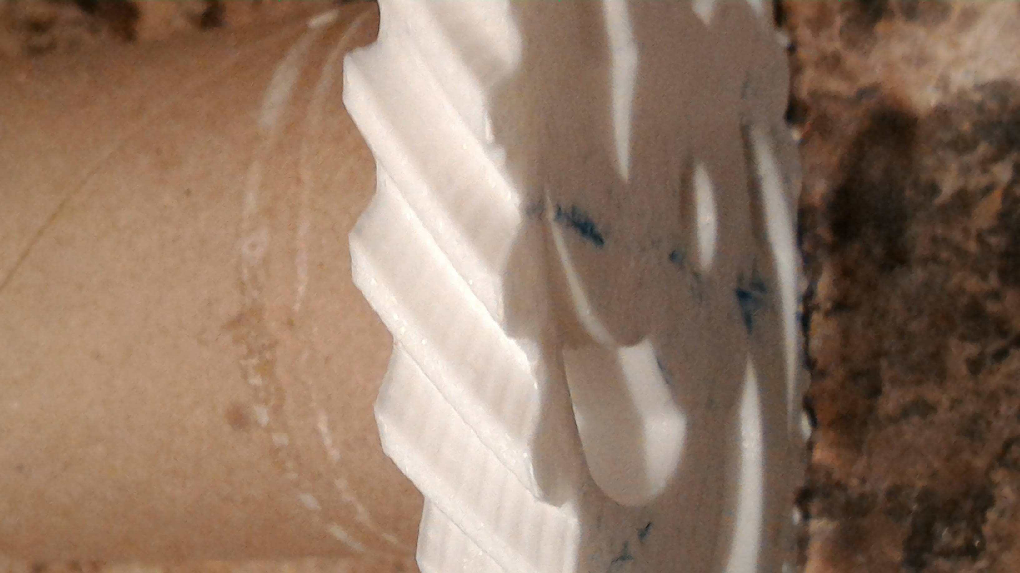
I have been building a smartrap printer. I know a lot have moved on to smart core but I was building a second printer and the smartrap was easily made. I am having issues with a banding pattern. I am thinking this is caused by a slight bend in my threaded rod causing the x axis to move slightly. I am wondering if anyone is using lead screws and if so what size? If anyone has any other ideas about this banding it would be appreciated.
I have been building a smartrap printer. I know a lot have moved on to smart core but I was building a second printer and the smartrap was easily made. I am having issues with a banding pattern. I am thinking this is caused by a slight bend in my threaded rod causing the x axis to move slightly. I am wondering if anyone is using lead screws and if so what size? If anyone has any other ideas about this banding it would be appreciated.
|
Re: Banding.... January 17, 2016 10:51AM |
Registered: 8 years ago Posts: 3,525 |
You should print a calibration set such as this one [www.thingiverse.com] it might make it more obvious.
This could be caused by z wobble which is usually related to the pitch of your z carriage screw versus your motor full step distance. In the case of smartrapcore alu it's a belt, correct? Does the idler at the other end of the belt from the motor, have teeth or is it smooth? There will be a slight difference in z axis height if the belt, on a smooth idler, is resting on a tooth or a flat between the teeth. Some people twist the belt over so that the back side runs on the smooth idler. You could try this it's a quick thing to check.
This could be caused by z wobble which is usually related to the pitch of your z carriage screw versus your motor full step distance. In the case of smartrapcore alu it's a belt, correct? Does the idler at the other end of the belt from the motor, have teeth or is it smooth? There will be a slight difference in z axis height if the belt, on a smooth idler, is resting on a tooth or a flat between the teeth. Some people twist the belt over so that the back side runs on the smooth idler. You could try this it's a quick thing to check.
|
Re: Banding.... January 17, 2016 11:28AM |
Registered: 8 years ago Posts: 22 |
Thanks for the reply. This is the original smartrap, I had a second piece of threaded rod that was straighter than the other end I was using so I replaced it and this made a big difference. I think if I were to find a lead screw rather than threaded rod it would likely fix the problem altogether. I am only able find 8mm lead screw so I may have to reprint the x axis plate to accommodate this.
|
Re: Banding.... January 18, 2016 03:11AM |
Registered: 8 years ago Posts: 3,525 |
I've got 8mm leadscrews on my i3 and I think the key to avoiding z banding is to calculate the travel distance of a full motor step.
So a tr8 leadscrew turns one revolution for 8mm travel, so if you have a 1.8 degree stepper motor that's 200 steps for 8mm so each full step is 0.04mm. If your layer heights are multiples of 0.04 ie realistically you can print 0.16,0.2,0.24,0.28,0.32 etc you should get less banding.
Original smartrap I think is an m6 threaded rod, this turns 1mm for a full evolution, check this by marking your coupler and moving z by 1mm it should be one revolution. So 1/200 = 0.005mm. Almost all layer heights are multiples of 0.005 so I wonder if this is the problem. A bent m6 rod would do it, a leadscrew is much less likely to be bent but it needs more torque to turn it. You'd be best with a bearing at the top so reprint that top piece to enclose a bearing, maybe remix this piece [www.thingiverse.com]
Keep the screw lubricated and maybe adjust your motor current higher if it struggles to turn it. You can attach the leadscrew to the carriage with an anti backlash nut [www.robotdigg.com]
You can buy a leadscrew with this nut for a few $ on ebay. You'll need to modify the z carriage.
|
Re: Banding.... January 18, 2016 09:22AM |
Registered: 8 years ago Posts: 22 |
Thanks again for the info. I will order the lead screw soon hopefully this will fix the problem. I am using a 5mm threaded rod atm. I did not calibrate the steps for this axis I just used what the firmware had by default. I may look into this because now that you have said this I think this may be contributing to my issue. Although the measurements I have taken are accurate. I will investigate this further when I get a chance.
Thanks again.
Thanks again.
Sorry, only registered users may post in this forum.