Home
>
RepRap User Groups
>
Europe
>
Italy RepRap User Group - Gruppo RepRap Italia
>
Stampa 3D per principianti
>
Topic
Aiuto inversione assi,endstop e configurazione home repetier e prima configurazione
Posted by fr4nc3sco
|
Aiuto inversione assi,endstop e configurazione home repetier e prima configurazione March 08, 2014 02:33PM |
Registered: 10 years ago Posts: 350 |
ho finito di montare la mia i3 e ovviamente iniziano i problemi di natura elettronica firmware dove veramente ne capisco poco...
ho avviato repetier,connesso la stamapante, e verificato che un po tutti gli assi e piani funzionassero.
ho problemi con alcuni assi che vanno nel verso opposto"z,y,estrusore" alla freccia premuta, spero si possano invertire tramite firmware perché al solo pensiero di dover risfasciare tutto e risaldare mi prenderebbe male....
ho testato anche gli endstop e vengono rilevati correttamente cioè legge se è chiuso o aperto, il problema è che pare fregarsene se in manuale uno ci va contro è normale?
premendo le varie casette sui vari assi non fa niente di che e comunque non riesco a far andare l'asse in negativo ma solo incrementi da 0a+
vi elenco il mio firmware caricato cosi da poter capire meglio se ci sono casini o altro e magari mi potrete dare una mano nelle varie righe da modificare

ah altra cosa ho provato anche hotbed il tutto montato con una piastra di mdf da 5mm sotto e comunque vedo che a 12,5v fatica ad andare sopra i 85° è normale? l'alimentatore è un dedicato da 30A di quelli di ebay
ho avviato repetier,connesso la stamapante, e verificato che un po tutti gli assi e piani funzionassero.
ho problemi con alcuni assi che vanno nel verso opposto"z,y,estrusore" alla freccia premuta, spero si possano invertire tramite firmware perché al solo pensiero di dover risfasciare tutto e risaldare mi prenderebbe male....
ho testato anche gli endstop e vengono rilevati correttamente cioè legge se è chiuso o aperto, il problema è che pare fregarsene se in manuale uno ci va contro è normale?
premendo le varie casette sui vari assi non fa niente di che e comunque non riesco a far andare l'asse in negativo ma solo incrementi da 0a+
vi elenco il mio firmware caricato cosi da poter capire meglio se ci sono casini o altro e magari mi potrete dare una mano nelle varie righe da modificare
grazie anticipatamente a chi mi darà una manoQuote
#ifndef CONFIGURATION_H
#define CONFIGURATION_H
// This configuration file contains the basic settings.
// Advanced settings can be found in Configuration_adv.h
// BASIC SETTINGS: select your board type, temperature sensor type, axis scaling, and endstop configuration
//===========================================================================
//============================= DELTA Printer ===============================
//===========================================================================
// For a Delta printer replace the configuration files with the files in the
// example_configurations/delta directory.
//
// User-specified version info of this build to display in [Pronterface, etc] terminal window during
// startup. Implementation of an idea by Prof Braino to inform user that any changes made to this
// build by the user have been successfully uploaded into firmware.
#define STRING_VERSION_CONFIG_H __DATE__ " " __TIME__ // build date and time
#define STRING_CONFIG_H_AUTHOR "(none, default config)" // Who made the changes.
// SERIAL_PORT selects which serial port should be used for communication with the host.
// This allows the connection of wireless adapters (for instance) to non-default port pins.
// Serial port 0 is still used by the Arduino bootloader regardless of this setting.
#define SERIAL_PORT 0
// This determines the communication speed of the printer
// This determines the communication speed of the printer
#define BAUDRATE 250000
// This enables the serial port associated to the Bluetooth interface
//#define BTENABLED // Enable BT interface on AT90USB devices
//// The following define selects which electronics board you have. Please choose the one that matches your setup
// 10 = Gen7 custom (Alfons3 Version) "https://github.com/Alfons3/Generation_7_Electronics"
// 11 = Gen7 v1.1, v1.2 = 11
// 12 = Gen7 v1.3
// 13 = Gen7 v1.4
// 2 = Cheaptronic v1.0
// 20 = Sethi 3D_1
// 3 = MEGA/RAMPS up to 1.2 = 3
// 33 = RAMPS 1.3 / 1.4 (Power outputs: Extruder, Fan, Bed)
// 34 = RAMPS 1.3 / 1.4 (Power outputs: Extruder0, Extruder1, Bed)
// 35 = RAMPS 1.3 / 1.4 (Power outputs: Extruder, Fan, Fan)
// 4 = Duemilanove w/ ATMega328P pin assignment
// 5 = Gen6
// 51 = Gen6 deluxe
// 6 = Sanguinololu < 1.2
// 62 = Sanguinololu 1.2 and above
// 63 = Melzi
// 64 = STB V1.1
// 65 = Azteeg X1
// 66 = Melzi with ATmega1284 (MaKr3d version)
// 67 = Azteeg X3
// 68 = Azteeg X3 Pro
// 7 = Ultimaker
// 71 = Ultimaker (Older electronics. Pre 1.5.4. This is rare)
// 72 = Ultimainboard 2.x (Uses TEMP_SENSOR 20)
// 77 = 3Drag Controller
// 8 = Teensylu
// 80 = Rumba
// 81 = Printrboard (AT90USB1286)
// 82 = Brainwave (AT90USB646)
// 83 = SAV Mk-I (AT90USB1286)
// 9 = Gen3+
// 70 = Megatronics
// 701= Megatronics v2.0
// 702= Minitronics v1.0
// 90 = Alpha OMCA board
// 91 = Final OMCA board
// 301= Rambo
// 21 = Elefu Ra Board (v3)
#ifndef MOTHERBOARD
#define MOTHERBOARD 33
#endif
// Define this to set a custom name for your generic Mendel,
// #define CUSTOM_MENDEL_NAME "This Mendel"
// Define this to set a unique identifier for this printer, (Used by some programs to differentiate between machines)
// You can use an online service to generate a random UUID. (eg [www.uuidgenerator.net])
// #define MACHINE_UUID "00000000-0000-0000-0000-000000000000"
// This defines the number of extruders
#define EXTRUDERS 1
//// The following define selects which power supply you have. Please choose the one that matches your setup
// 1 = ATX
// 2 = X-Box 360 203Watts (the blue wire connected to PS_ON and the red wire to VCC)
#define POWER_SUPPLY 1
// Define this to have the electronics keep the power supply off on startup. If you don't know what this is leave it.
// #define PS_DEFAULT_OFF
//===========================================================================
//=============================Thermal Settings ============================
//===========================================================================
//
//--NORMAL IS 4.7kohm PULLUP!-- 1kohm pullup can be used on hotend sensor, using correct resistor and table
//
//// Temperature sensor settings:
// -2 is thermocouple with MAX6675 (only for sensor 0)
// -1 is thermocouple with AD595
// 0 is not used
// 1 is 100k thermistor - best choice for EPCOS 100k (4.7k pullup)
// 2 is 200k thermistor - ATC Semitec 204GT-2 (4.7k pullup)
// 3 is Mendel-parts thermistor (4.7k pullup)
// 4 is 10k thermistor !! do not use it for a hotend. It gives bad resolution at high temp. !!
// 5 is 100K thermistor - ATC Semitec 104GT-2 (Used in ParCan & J-Head) (4.7k pullup)
// 6 is 100k EPCOS - Not as accurate as table 1 (created using a fluke thermocouple) (4.7k pullup)
// 7 is 100k Honeywell thermistor 135-104LAG-J01 (4.7k pullup)
// 71 is 100k Honeywell thermistor 135-104LAF-J01 (4.7k pullup)
// 8 is 100k 0603 SMD Vishay NTCS0603E3104FXT (4.7k pullup)
// 9 is 100k GE Sensing AL03006-58.2K-97-G1 (4.7k pullup)
// 10 is 100k RS thermistor 198-961 (4.7k pullup)
// 20 is the PT100 circuit found in the Ultimainboard V2.x
// 60 is 100k Maker's Tool Works Kapton Bed Thermistor
//
// 1k ohm pullup tables - This is not normal, you would have to have changed out your 4.7k for 1k
// (but gives greater accuracy and more stable PID)
// 51 is 100k thermistor - EPCOS (1k pullup)
// 52 is 200k thermistor - ATC Semitec 204GT-2 (1k pullup)
// 55 is 100k thermistor - ATC Semitec 104GT-2 (Used in ParCan & J-Head) (1k pullup)
//
// 1047 is Pt1000 with 4k7 pullup
// 1010 is Pt1000 with 1k pullup (non standard)
// 147 is Pt100 with 4k7 pullup
// 110 is Pt100 with 1k pullup (non standard)
#define TEMP_SENSOR_0 1
#define TEMP_SENSOR_1 0
#define TEMP_SENSOR_2 0
#define TEMP_SENSOR_BED 1
// This makes temp sensor 1 a redundant sensor for sensor 0. If the temperatures difference between these sensors is to high the print will be aborted.
//#define TEMP_SENSOR_1_AS_REDUNDANT
#define MAX_REDUNDANT_TEMP_SENSOR_DIFF 10
// Actual temperature must be close to target for this long before M109 returns success
#define TEMP_RESIDENCY_TIME 10 // (seconds)
#define TEMP_HYSTERESIS 3 // (degC) range of +/- temperatures considered "close" to the target one
#define TEMP_WINDOW 1 // (degC) Window around target to start the residency timer x degC early.
// The minimal temperature defines the temperature below which the heater will not be enabled It is used
// to check that the wiring to the thermistor is not broken.
// Otherwise this would lead to the heater being powered on all the time.
#define HEATER_0_MINTEMP 5
#define HEATER_1_MINTEMP 5
#define HEATER_2_MINTEMP 5
#define BED_MINTEMP 5
// When temperature exceeds max temp, your heater will be switched off.
// This feature exists to protect your hotend from overheating accidentally, but *NOT* from thermistor short/failure!
// You should use MINTEMP for thermistor short/failure protection.
#define HEATER_0_MAXTEMP 275
#define HEATER_1_MAXTEMP 275
#define HEATER_2_MAXTEMP 275
#define BED_MAXTEMP 150
// If your bed has low resistance e.g. .6 ohm and throws the fuse you can duty cycle it to reduce the
// average current. The value should be an integer and the heat bed will be turned on for 1 interval of
// HEATER_BED_DUTY_CYCLE_DIVIDER intervals.
//#define HEATER_BED_DUTY_CYCLE_DIVIDER 4
// If you want the M105 heater power reported in watts, define the BED_WATTS, and (shared for all extruders) EXTRUDER_WATTS
//#define EXTRUDER_WATTS (12.0*12.0/6.7) // P=I^2/R
//#define BED_WATTS (12.0*12.0/1.1) // P=I^2/R
// PID settings:
// Comment the following line to disable PID and enable bang-bang.
#define PIDTEMP
#define BANG_MAX 255 // limits current to nozzle while in bang-bang mode; 255=full current
#define PID_MAX 255 // limits current to nozzle while PID is active (see PID_FUNCTIONAL_RANGE below); 255=full current
#ifdef PIDTEMP
//#define PID_DEBUG // Sends debug data to the serial port.
//#define PID_OPENLOOP 1 // Puts PID in open loop. M104/M140 sets the output power from 0 to PID_MAX
#define PID_FUNCTIONAL_RANGE 10 // If the temperature difference between the target temperature and the actual temperature
// is more then PID_FUNCTIONAL_RANGE then the PID will be shut off and the heater will be set to min/max.
#define PID_INTEGRAL_DRIVE_MAX 255 //limit for the integral term
#define K1 0.95 //smoothing factor within the PID
#define PID_dT ((OVERSAMPLENR * 8.0)/(F_CPU / 64.0 / 256.0)) //sampling period of the temperature routine
// If you are using a pre-configured hotend then you can use one of the value sets by uncommenting it
// Ultimaker
#define DEFAULT_Kp 22.2
#define DEFAULT_Ki 1.08
#define DEFAULT_Kd 114
// MakerGear
// #define DEFAULT_Kp 7.0
// #define DEFAULT_Ki 0.1
// #define DEFAULT_Kd 12
// Mendel Parts V9 on 12V
// #define DEFAULT_Kp 63.0
// #define DEFAULT_Ki 2.25
// #define DEFAULT_Kd 440
#endif // PIDTEMP
// Bed Temperature Control
// Select PID or bang-bang with PIDTEMPBED. If bang-bang, BED_LIMIT_SWITCHING will enable hysteresis
//
// Uncomment this to enable PID on the bed. It uses the same frequency PWM as the extruder.
// If your PID_dT above is the default, and correct for your hardware/configuration, that means 7.689Hz,
// which is fine for driving a square wave into a resistive load and does not significantly impact you FET heating.
// This also works fine on a Fotek SSR-10DA Solid State Relay into a 250W heater.
// If your configuration is significantly different than this and you don't understand the issues involved, you probably
// shouldn't use bed PID until someone else verifies your hardware works.
// If this is enabled, find your own PID constants below.
//#define PIDTEMPBED
//
//#define BED_LIMIT_SWITCHING
// This sets the max power delivered to the bed, and replaces the HEATER_BED_DUTY_CYCLE_DIVIDER option.
// all forms of bed control obey this (PID, bang-bang, bang-bang with hysteresis)
// setting this to anything other than 255 enables a form of PWM to the bed just like HEATER_BED_DUTY_CYCLE_DIVIDER did,
// so you shouldn't use it unless you are OK with PWM on your bed. (see the comment on enabling PIDTEMPBED)
#define MAX_BED_POWER 255 // limits duty cycle to bed; 255=full current
#ifdef PIDTEMPBED
//120v 250W silicone heater into 4mm borosilicate (MendelMax 1.5+)
//from FOPDT model - kp=.39 Tp=405 Tdead=66, Tc set to 79.2, aggressive factor of .15 (vs .1, 1, 10)
#define DEFAULT_bedKp 10.00
#define DEFAULT_bedKi .023
#define DEFAULT_bedKd 305.4
//120v 250W silicone heater into 4mm borosilicate (MendelMax 1.5+)
//from pidautotune
// #define DEFAULT_bedKp 97.1
// #define DEFAULT_bedKi 1.41
// #define DEFAULT_bedKd 1675.16
// FIND YOUR OWN: "M303 E-1 C8 S90" to run autotune on the bed at 90 degreesC for 8 cycles.
#endif // PIDTEMPBED
//this prevents dangerous Extruder moves, i.e. if the temperature is under the limit
//can be software-disabled for whatever purposes by
#define PREVENT_DANGEROUS_EXTRUDE
//if PREVENT_DANGEROUS_EXTRUDE is on, you can still disable (uncomment) very long bits of extrusion separately.
#define PREVENT_LENGTHY_EXTRUDE
#define EXTRUDE_MINTEMP 170
#define EXTRUDE_MAXLENGTH (X_MAX_LENGTH+Y_MAX_LENGTH) //prevent extrusion of very large distances.
//===========================================================================
//=============================Mechanical Settings===========================
//===========================================================================
// Uncomment the following line to enable CoreXY kinematics
// #define COREXY
// coarse Endstop Settings
#define ENDSTOPPULLUPS // Comment this out (using // at the start of the line) to disable the endstop pullup resistors
#ifndef ENDSTOPPULLUPS
// fine endstop settings: Individual pullups. will be ignored if ENDSTOPPULLUPS is defined
// #define ENDSTOPPULLUP_XMAX
// #define ENDSTOPPULLUP_YMAX
// #define ENDSTOPPULLUP_ZMAX
// #define ENDSTOPPULLUP_XMIN
// #define ENDSTOPPULLUP_YMIN
// #define ENDSTOPPULLUP_ZMIN
#endif
#ifdef ENDSTOPPULLUPS
#define ENDSTOPPULLUP_XMAX
#define ENDSTOPPULLUP_YMAX
#define ENDSTOPPULLUP_ZMAX
#define ENDSTOPPULLUP_XMIN
#define ENDSTOPPULLUP_YMIN
#define ENDSTOPPULLUP_ZMIN
#endif
// The pullups are needed if you directly connect a mechanical endswitch between the signal and ground pins.
const bool X_MIN_ENDSTOP_INVERTING = true; // set to true to invert the logic of the endstop.
const bool Y_MIN_ENDSTOP_INVERTING = true; // set to true to invert the logic of the endstop.
const bool Z_MIN_ENDSTOP_INVERTING = true; // set to true to invert the logic of the endstop.
const bool X_MAX_ENDSTOP_INVERTING = true; // set to true to invert the logic of the endstop.
const bool Y_MAX_ENDSTOP_INVERTING = true; // set to true to invert the logic of the endstop.
const bool Z_MAX_ENDSTOP_INVERTING = true; // set to true to invert the logic of the endstop.
#define DISABLE_MAX_ENDSTOPS
//#define DISABLE_MIN_ENDSTOPS
// Disable max endstops for compatibility with endstop checking routine
#if defined(COREXY) && !defined(DISABLE_MAX_ENDSTOPS)
#define DISABLE_MAX_ENDSTOPS
#endif
// For Inverting Stepper Enable Pins (Active Low) use 0, Non Inverting (Active High) use 1
#define X_ENABLE_ON 0
#define Y_ENABLE_ON 0
#define Z_ENABLE_ON 0
#define E_ENABLE_ON 0 // For all extruders
// Disables axis when it's not being used.
#define DISABLE_X false
#define DISABLE_Y false
#define DISABLE_Z false
#define DISABLE_E false // For all extruders
#define INVERT_X_DIR false // for Mendel set to false, for Orca set to true
#define INVERT_Y_DIR false // for Mendel set to true, for Orca set to false
#define INVERT_Z_DIR true // for Mendel set to false, for Orca set to true
#define INVERT_E0_DIR false // for direct drive extruder v9 set to true, for geared extruder set to false
#define INVERT_E1_DIR false // for direct drive extruder v9 set to true, for geared extruder set to false
#define INVERT_E2_DIR false // for direct drive extruder v9 set to true, for geared extruder set to false
// ENDSTOP SETTINGS:
// Sets direction of endstops when homing; 1=MAX, -1=MIN
#define X_HOME_DIR -1
#define Y_HOME_DIR -1
#define Z_HOME_DIR -1
#define min_software_endstops true // If true, axis won't move to coordinates less than HOME_POS.
#define max_software_endstops true // If true, axis won't move to coordinates greater than the defined lengths below.
// Travel limits after homing
#define X_MAX_POS 205
#define X_MIN_POS 0
#define Y_MAX_POS 205
#define Y_MIN_POS 0
#define Z_MAX_POS 200
#define Z_MIN_POS 0
#define X_MAX_LENGTH (X_MAX_POS - X_MIN_POS)
#define Y_MAX_LENGTH (Y_MAX_POS - Y_MIN_POS)
#define Z_MAX_LENGTH (Z_MAX_POS - Z_MIN_POS)
//============================= Bed Auto Leveling ===========================
//#define ENABLE_AUTO_BED_LEVELING // Delete the comment to enable (remove // at the start of the line)
#ifdef ENABLE_AUTO_BED_LEVELING
// these are the positions on the bed to do the probing
#define LEFT_PROBE_BED_POSITION 15
#define RIGHT_PROBE_BED_POSITION 170
#define BACK_PROBE_BED_POSITION 180
#define FRONT_PROBE_BED_POSITION 20
// these are the offsets to the probe relative to the extruder tip (Hotend - Probe)
#define X_PROBE_OFFSET_FROM_EXTRUDER -25
#define Y_PROBE_OFFSET_FROM_EXTRUDER -29
#define Z_PROBE_OFFSET_FROM_EXTRUDER -12.35
#define Z_RAISE_BEFORE_HOMING 4 // (in mm) Raise Z before homing (G28) for Probe Clearance.
// Be sure you have this distance over your Z_MAX_POS in case
#define XY_TRAVEL_SPEED 8000 // X and Y axis travel speed between probes, in mm/min
#define Z_RAISE_BEFORE_PROBING 15 //How much the extruder will be raised before traveling to the first probing point.
#define Z_RAISE_BETWEEN_PROBINGS 5 //How much the extruder will be raised when traveling from between next probing points
//If defined, the Probe servo will be turned on only during movement and then turned off to avoid jerk
//The value is the delay to turn the servo off after powered on - depends on the servo speed; 300ms is good value, but you can try lower it.
// You MUST HAVE the SERVO_ENDSTOPS defined to use here a value higher than zero otherwise your code will not compile.
// #define PROBE_SERVO_DEACTIVATION_DELAY 300
//If you have enabled the Bed Auto Leveling and are using the same Z Probe for Z Homing,
//it is highly recommended you let this Z_SAFE_HOMING enabled!!!
#define Z_SAFE_HOMING // This feature is meant to avoid Z homing with probe outside the bed area.
// When defined, it will:
// - Allow Z homing only after X and Y homing AND stepper drivers still enabled
// - If stepper drivers timeout, it will need X and Y homing again before Z homing
// - Position the probe in a defined XY point before Z Homing when homing all axis (G28)
// - Block Z homing only when the probe is outside bed area.
#ifdef Z_SAFE_HOMING
#define Z_SAFE_HOMING_X_POINT (X_MAX_LENGTH/2) // X point for Z homing when homing all axis (G28)
#define Z_SAFE_HOMING_Y_POINT (Y_MAX_LENGTH/2) // Y point for Z homing when homing all axis (G28)
#endif
// with accurate bed leveling, the bed is sampled in a ACCURATE_BED_LEVELING_POINTSxACCURATE_BED_LEVELING_POINTS grid and least squares solution is calculated
// Note: this feature occupies 10'206 byte
#define ACCURATE_BED_LEVELING
#ifdef ACCURATE_BED_LEVELING
// I wouldn't see a reason to go above 3 (=9 probing points on the bed)
#define ACCURATE_BED_LEVELING_POINTS 2
#endif
#endif
// The position of the homing switches
//#define MANUAL_HOME_POSITIONS // If defined, MANUAL_*_HOME_POS below will be used
//#define BED_CENTER_AT_0_0 // If defined, the center of the bed is at (X=0, Y=0)
//Manual homing switch locations:
// For deltabots this means top and center of the Cartesian print volume.
#define MANUAL_X_HOME_POS 0
#define MANUAL_Y_HOME_POS 0
#define MANUAL_Z_HOME_POS 0
//#define MANUAL_Z_HOME_POS 402 // For delta: Distance between nozzle and print surface after homing.
//// MOVEMENT SETTINGS
#define NUM_AXIS 4 // The axis order in all axis related arrays is X, Y, Z, E
#define HOMING_FEEDRATE {50*60, 50*60, 4*60, 0} // set the homing speeds (mm/min)
// default settings
#define DEFAULT_AXIS_STEPS_PER_UNIT {200,200,5120,1353 } // default step per unit 78.7402,78.7402,200.0*8/3,760*1.1 // default steps per unit for Ultimaker
#define DEFAULT_MAX_FEEDRATE {500, 500, 5, 25} // (mm/sec)
#define DEFAULT_MAX_ACCELERATION {9000,9000,100,5000} // X, Y, Z, E maximum start speed for accelerated moves. E default values are good for Skeinforge 40+, for older versions raise them a lot.
#define DEFAULT_ACCELERATION 3000 // X, Y, Z and E max acceleration in mm/s^2 for printing moves
#define DEFAULT_RETRACT_ACCELERATION 3000 // X, Y, Z and E max acceleration in mm/s^2 for retracts
// Offset of the extruders (uncomment if using more than one and relying on firmware to position when changing).
// The offset has to be X=0, Y=0 for the extruder 0 hotend (default extruder).
// For the other hotends it is their distance from the extruder 0 hotend.
// #define EXTRUDER_OFFSET_X {0.0, 20.00} // (in mm) for each extruder, offset of the hotend on the X axis
// #define EXTRUDER_OFFSET_Y {0.0, 5.00} // (in mm) for each extruder, offset of the hotend on the Y axis
// The speed change that does not require acceleration (i.e. the software might assume it can be done instantaneously)
#define DEFAULT_XYJERK 20.0 // (mm/sec)
#define DEFAULT_ZJERK 0.4 // (mm/sec)
#define DEFAULT_EJERK 5.0 // (mm/sec)
//===========================================================================
//=============================Additional Features===========================
//===========================================================================
// EEPROM
// The microcontroller can store settings in the EEPROM, e.g. max velocity...
// M500 - stores parameters in EEPROM
// M501 - reads parameters from EEPROM (if you need reset them after you changed them temporarily).
// M502 - reverts to the default "factory settings". You still need to store them in EEPROM afterwards if you want to.
//define this to enable EEPROM support
//#define EEPROM_SETTINGS
//to disable EEPROM Serial responses and decrease program space by ~1700 byte: comment this out:
// please keep turned on if you can.
//#define EEPROM_CHITCHAT
// Preheat Constants
#define PLA_PREHEAT_HOTEND_TEMP 180
#define PLA_PREHEAT_HPB_TEMP 70
#define PLA_PREHEAT_FAN_SPEED 255 // Insert Value between 0 and 255
#define ABS_PREHEAT_HOTEND_TEMP 240
#define ABS_PREHEAT_HPB_TEMP 100
#define ABS_PREHEAT_FAN_SPEED 255 // Insert Value between 0 and 255
//LCD and SD support
//#define ULTRA_LCD //general LCD support, also 16x2
//#define DOGLCD // Support for SPI LCD 128x64 (Controller ST7565R graphic Display Family)
//#define SDSUPPORT // Enable SD Card Support in Hardware Console
//#define SDSLOW // Use slower SD transfer mode (not normally needed - uncomment if you're getting volume init error)
//#define ENCODER_PULSES_PER_STEP 1 // Increase if you have a high resolution encoder
//#define ENCODER_STEPS_PER_MENU_ITEM 5 // Set according to ENCODER_PULSES_PER_STEP or your liking
//#define ULTIMAKERCONTROLLER //as available from the Ultimaker online store.
//#define ULTIPANEL //the UltiPanel as on Thingiverse
//#define LCD_FEEDBACK_FREQUENCY_HZ 1000 // this is the tone frequency the buzzer plays when on UI feedback. ie Screen Click
//#define LCD_FEEDBACK_FREQUENCY_DURATION_MS 100 // the duration the buzzer plays the UI feedback sound. ie Screen Click
// The MaKr3d Makr-Panel with graphic controller and SD support
// [reprap.org]
//#define MAKRPANEL
// The RepRapDiscount Smart Controller (white PC
// [reprap.org]
//#define REPRAP_DISCOUNT_SMART_CONTROLLER
// The GADGETS3D G3D LCD/SD Controller (blue PC
// [reprap.org]
//#define G3D_PANEL
// The RepRapDiscount FULL GRAPHIC Smart Controller (quadratic white PC
// [reprap.org]
//
// ==> REMEMBER TO INSTALL U8glib to your ARDUINO library folder: [code.google.com]
//#define REPRAP_DISCOUNT_FULL_GRAPHIC_SMART_CONTROLLER
// The RepRapWorld REPRAPWORLD_KEYPAD v1.1
// [reprapworld.com]
//#define REPRAPWORLD_KEYPAD
//#define REPRAPWORLD_KEYPAD_MOVE_STEP 10.0 // how much should be moved when a key is pressed, eg 10.0 means 10mm per click
// The Elefu RA Board Control Panel
// [www.elefu.com]
// REMEMBER TO INSTALL LiquidCrystal_I2C.h in your ARUDINO library folder: [github.com]
//#define RA_CONTROL_PANEL
//automatic expansion
#if defined (MAKRPANEL)
#define DOGLCD
#define SDSUPPORT
#define ULTIPANEL
#define NEWPANEL
#define DEFAULT_LCD_CONTRAST 17
#endif
#if defined (REPRAP_DISCOUNT_FULL_GRAPHIC_SMART_CONTROLLER)
#define DOGLCD
#define U8GLIB_ST7920
#define REPRAP_DISCOUNT_SMART_CONTROLLER
#endif
#if defined(ULTIMAKERCONTROLLER) || defined(REPRAP_DISCOUNT_SMART_CONTROLLER) || defined(G3D_PANEL)
#define ULTIPANEL
#define NEWPANEL
#endif
#if defined(REPRAPWORLD_KEYPAD)
#define NEWPANEL
#define ULTIPANEL
#endif
#if defined(RA_CONTROL_PANEL)
#define ULTIPANEL
#define NEWPANEL
#define LCD_I2C_TYPE_PCA8574
#define LCD_I2C_ADDRESS 0x27 // I2C Address of the port expander
#endif
//I2C PANELS
//#define LCD_I2C_SAINSMART_YWROBOT
#ifdef LCD_I2C_SAINSMART_YWROBOT
// This uses the LiquidCrystal_I2C library ( [bitbucket.org] )
// Make sure it is placed in the Arduino libraries directory.
#define LCD_I2C_TYPE_PCF8575
#define LCD_I2C_ADDRESS 0x27 // I2C Address of the port expander
#define NEWPANEL
#define ULTIPANEL
#endif
// PANELOLU2 LCD with status LEDs, separate encoder and click inputs
//#define LCD_I2C_PANELOLU2
#ifdef LCD_I2C_PANELOLU2
// This uses the LiquidTWI2 library v1.2.3 or later ( [github.com] )
// Make sure the LiquidTWI2 directory is placed in the Arduino or Sketchbook libraries subdirectory.
// (v1.2.3 no longer requires you to define PANELOLU in the LiquidTWI2.h library header file)
// Note: The PANELOLU2 encoder click input can either be directly connected to a pin
// (if BTN_ENC defined to != -1) or read through I2C (when BTN_ENC == -1).
#define LCD_I2C_TYPE_MCP23017
#define LCD_I2C_ADDRESS 0x20 // I2C Address of the port expander
#define LCD_USE_I2C_BUZZER //comment out to disable buzzer on LCD
#define NEWPANEL
#define ULTIPANEL
#ifndef ENCODER_PULSES_PER_STEP
#define ENCODER_PULSES_PER_STEP 4
#endif
#ifndef ENCODER_STEPS_PER_MENU_ITEM
#define ENCODER_STEPS_PER_MENU_ITEM 1
#endif
#ifdef LCD_USE_I2C_BUZZER
#define LCD_FEEDBACK_FREQUENCY_HZ 1000
#define LCD_FEEDBACK_FREQUENCY_DURATION_MS 100
#endif
#endif
// Panucatt VIKI LCD with status LEDs, integrated click & L/R/U/P buttons, separate encoder inputs
//#define LCD_I2C_VIKI
#ifdef LCD_I2C_VIKI
// This uses the LiquidTWI2 library v1.2.3 or later ( [github.com] )
// Make sure the LiquidTWI2 directory is placed in the Arduino or Sketchbook libraries subdirectory.
// Note: The pause/stop/resume LCD button pin should be connected to the Arduino
// BTN_ENC pin (or set BTN_ENC to -1 if not used)
#define LCD_I2C_TYPE_MCP23017
#define LCD_I2C_ADDRESS 0x20 // I2C Address of the port expander
#define LCD_USE_I2C_BUZZER //comment out to disable buzzer on LCD (requires LiquidTWI2 v1.2.3 or later)
#define NEWPANEL
#define ULTIPANEL
#endif
// Shift register panels
// ---------------------
// 2 wire Non-latching LCD SR from:
// [bitbucket.org]
//#define SR_LCD
#ifdef SR_LCD
#define SR_LCD_2W_NL // Non latching 2 wire shift register
//#define NEWPANEL
#endif
#ifdef ULTIPANEL
// #define NEWPANEL //enable this if you have a click-encoder panel
#define SDSUPPORT
#define ULTRA_LCD
#ifdef DOGLCD // Change number of lines to match the DOG graphic display
#define LCD_WIDTH 20
#define LCD_HEIGHT 5
#else
#define LCD_WIDTH 20
#define LCD_HEIGHT 4
#endif
#else //no panel but just LCD
#ifdef ULTRA_LCD
#ifdef DOGLCD // Change number of lines to match the 128x64 graphics display
#define LCD_WIDTH 20
#define LCD_HEIGHT 5
#else
#define LCD_WIDTH 16
#define LCD_HEIGHT 2
#endif
#endif
#endif
// default LCD contrast for dogm-like LCD displays
#ifdef DOGLCD
# ifndef DEFAULT_LCD_CONTRAST
# define DEFAULT_LCD_CONTRAST 32
# endif
#endif
// Increase the FAN pwm frequency. Removes the PWM noise but increases heating in the FET/Arduino
//#define FAST_PWM_FAN
// Temperature status LEDs that display the hotend and bet temperature.
// If all hotends and bed temperature and temperature setpoint are < 54C then the BLUE led is on.
// Otherwise the RED led is on. There is 1C hysteresis.
//#define TEMP_STAT_LEDS
// Use software PWM to drive the fan, as for the heaters. This uses a very low frequency
// which is not ass annoying as with the hardware PWM. On the other hand, if this frequency
// is too low, you should also increment SOFT_PWM_SCALE.
//#define FAN_SOFT_PWM
// Incrementing this by 1 will double the software PWM frequency,
// affecting heaters, and the fan if FAN_SOFT_PWM is enabled.
// However, control resolution will be halved for each increment;
// at zero value, there are 128 effective control positions.
#define SOFT_PWM_SCALE 0
// M240 Triggers a camera by emulating a Canon RC-1 Remote
// Data from: [www.doc-diy.net]
// #define PHOTOGRAPH_PIN 23
// SF send wrong arc g-codes when using Arc Point as fillet procedure
//#define SF_ARC_FIX
// Support for the BariCUDA Paste Extruder.
//#define BARICUDA
//define BlinkM/CyzRgb Support
//#define BLINKM
/*********************************************************************[/color]
* R/C SERVO support
* Sponsored by TrinityLabs, Reworked by codexmas
**********************************************************************/
// Number of servos
//
// If you select a configuration below, this will receive a default value and does not need to be set manually
// set it manually if you have more servos than extruders and wish to manually control some
// leaving it undefined or defining as 0 will disable the servo subsystem
// If unsure, leave commented / disabled
//
//#define NUM_SERVOS 3 // Servo index starts with 0 for M280 command
// Servo Endstops
//
// This allows for servo actuated endstops, primary usage is for the Z Axis to eliminate calibration or bed height changes.
// Use M206 command to correct for switch height offset to actual nozzle height. Store that setting with M500.
//
//#define SERVO_ENDSTOPS {-1, -1, 0} // Servo index for X, Y, Z. Disable with -1
//#define SERVO_ENDSTOP_ANGLES {0,0, 0,0, 70,0} // X,Y,Z Axis Extend and Retract angles
#include "Configuration_adv.h"
#include "thermistortables.h"
#endif //__CONFIGURATION_H

ah altra cosa ho provato anche hotbed il tutto montato con una piastra di mdf da 5mm sotto e comunque vedo che a 12,5v fatica ad andare sopra i 85° è normale? l'alimentatore è un dedicato da 30A di quelli di ebay
|
Re: Aiuto inversione assi,endstop e configurazione home repetier e prima configurazione March 08, 2014 06:03PM |
Registered: 10 years ago Posts: 1,714 |
Le direzioni le gestisci qui
#define INVERT_X_DIR false // for Mendel set to false, for Orca set to true
#define INVERT_Y_DIR false // for Mendel set to true, for Orca set to false
#define INVERT_Z_DIR true // for Mendel set to false, for Orca set to true
#define INVERT_E0_DIR false // for direct drive extruder v9 set to true, for geared extruder set to false
#define INVERT_E1_DIR false // for direct drive extruder v9 set to true, for geared extruder set to false
#define INVERT_E2_DIR false // for direct drive extruder v9 set to true, for geared extruder set to false
se non gli dai l'home gli assi vanno solo in una direzione.
se non vanno in home devi ricontrollare gli endstop.
R2 Evo-Prometeo-Poseidon-Titan0
Multiextruder NPr3-WR4
[www.3dmakerlab.it]
|
Re: Aiuto inversione assi,endstop e configurazione home repetier e prima configurazione March 09, 2014 04:52AM |
Registered: 10 years ago Posts: 350 |
ok questa parte e risolta
invertiti i motori da firmware come pure gli endstop adesso funziona tutto
tarati i motori x e y sullo z ho visto che nell inversione di senso perde circa 1 decimo si puo compensare?
altra domanda l'estrusore non c'è una tabella per regolarlo almeno di grosso a quanto andrebbe settato per iniziare i test? ho visto che per funzionare il motore bisogna che hotend sia ad almeno 175° non è che si guasta ad andare a vuoto senza cavo giusto oppure c'è modo di modificare tale opzione? cosi evito ustioni con pezzi penzolanti
una volta che inserisco il cavo e testo i reali millimetri di estrusione puo essere riusato per un ulteriore prova oppure quel pezzo va buttato?
per il momento ci dovremmo essere con le domande
|
Re: Aiuto inversione assi,endstop e configurazione home repetier e prima configurazione March 09, 2014 05:55AM |
Registered: 10 years ago Posts: 1,714 |
Per la perdita del decimo, probabilmente ti perde qualche micropasso: abbassa drasticamente le accelerazioni X,Y e E: portale a 1500 o 2000 e vedi se fa lo stasso, cmq poi lasciale basse.
Ci sono dei calcoli che potresti fare in base al tuo accoppiamento motore/hobbed bolt, il diametro della hobbed bolt, il diametro del filo e le caratteristiche elettriche del motore (step ecc.)... ma chi te lo fa fare? alla fine devi comunque fare comunque una bella proporzione perchè i calcoli non rispecchiano mai la realtà (si, lo so, fa strano ma questo è un'universo a se ): metti 700 e prova.
La taratura andrebbe fatta a vuoto, ma se tieni molto bassa la velocità di estrusione e l'accelerazione di modo che sei sicuro che non ci siano slittamenti del cavo e perdita di passi, puoi farla anche con l'hotend montato.
Se la fai a vuoto non essendosi sciolto il filo lo puoi riutilizzare
Ciao Fra
R2 Evo-Prometeo-Poseidon-Titan0
Multiextruder NPr3-WR4
[www.3dmakerlab.it]
Ci sono dei calcoli che potresti fare in base al tuo accoppiamento motore/hobbed bolt, il diametro della hobbed bolt, il diametro del filo e le caratteristiche elettriche del motore (step ecc.)... ma chi te lo fa fare? alla fine devi comunque fare comunque una bella proporzione perchè i calcoli non rispecchiano mai la realtà (si, lo so, fa strano ma questo è un'universo a se
): metti 700 e prova.La taratura andrebbe fatta a vuoto, ma se tieni molto bassa la velocità di estrusione e l'accelerazione di modo che sei sicuro che non ci siano slittamenti del cavo e perdita di passi, puoi farla anche con l'hotend montato.
Se la fai a vuoto non essendosi sciolto il filo lo puoi riutilizzare
Ciao Fra
R2 Evo-Prometeo-Poseidon-Titan0
Multiextruder NPr3-WR4
[www.3dmakerlab.it]
|
Re: Aiuto inversione assi,endstop e configurazione home repetier e prima configurazione March 09, 2014 06:14AM |
Registered: 10 years ago Posts: 350 |
be credevo pure io fosse una perdita di passi pero alla fine se faccio tipo 0 +10 misuro +10 misuro e è 115,20 do +20 e misuro è 135.20 do +20 ed è 155.20 do -30 ed è 125.30 do+30 ed è 155.20 quindi e proprio il gioco che ha il dato sulla vite che porta a un errore in caso di inversione pero quell errore poi in teoria si riperquote su 1 layer che praticamente verrebbe doppio e a catena su tutti gli altri no? oppure è un errore trascurabile?Quote
Nicola P
Per la perdita del decimo, probabilmente ti perde qualche micropasso: abbassa drasticamente le accelerazioni X,Y e E: portale a 1500 o 2000 e vedi se fa lo stasso, cmq poi lasciale basse.
Ci sono dei calcoli che potresti fare in base al tuo accoppiamento motore/hobbed bolt, il diametro della hobbed bolt, il diametro del filo e le caratteristiche elettriche del motore (step ecc.)... ma chi te lo fa fare? alla fine devi comunque fare comunque una bella proporzione perchè i calcoli non rispecchiano mai la realtà (si, lo so, fa strano ma questo è un'universo a se
La taratura andrebbe fatta a vuoto, ma se tieni molto bassa la velocità di estrusione e l'accelerazione di modo che sei sicuro che non ci siano slittamenti del cavo e perdita di passi, puoi farla anche con l'hotend montato.
Se la fai a vuoto non essendosi sciolto il filo lo puoi riutilizzare
Ciao Fra
provo comunque ad abbassare le accelerazioni tanto alla fine non è che cambi molto nelle tempistiche di realizzazione di pezzi singoli
per la taratura dell estrusore quindi diciamo a hotend levato va comunque fatto scaldare altrimenti non si muove il motore e c'è una stringa da poter modificare per estrudere a freddo fare i calcoli dovuti ecc..?
altra cosa ho provato il mio piano e oltre 94,3° non c'è verso di andare suggerimenti senza stravolgere tutto al di sotto c'è gia un piano da 5mm di mdf per mantenere più possibile il calore ma comunque non basta
Edited 1 time(s). Last edit at 03/09/2014 06:17AM by fr4nc3sco.
|
Re: Aiuto inversione assi,endstop e configurazione home repetier e prima configurazione March 09, 2014 06:21AM |
Registered: 10 years ago Posts: 6,409 |
Quote
fr4nc3sco
per la taratura dell estrusore quindi diciamo a hotend levato va comunque fatto scaldare altrimenti non si muove il motore e c'è una stringa da poter modificare per estrudere a freddo fare i calcoli dovuti ecc..?
Quote
//this prevents dangerous Extruder moves, i.e. if the temperature is under the limit
//can be software-disabled for whatever purposes by
#define PREVENT_DANGEROUS_EXTRUDE
//if PREVENT_DANGEROUS_EXTRUDE is on, you can still disable (uncomment) very long bits of extrusion separately.
#define PREVENT_LENGTHY_EXTRUDE
#define EXTRUDE_MINTEMP 170
#define EXTRUDE_MAXLENGTH (X_MAX_LENGTH+Y_MAX_LENGTH) //prevent extrusion of very large distances.
O togli define PREVENT_DANGEROUS_EXTRUDE o metti a 0 define EXTRUDE_MINTEMP.
Serve per non far girare il motore fino a quando la temperatura non è al di sopra del valore messo in EXTRUDE_MINTEMP. Nel caso tuo 170°.
in questo modo puoi fare prove a vuoto senza dover scaldare l'HOTEND.
|
Re: Aiuto inversione assi,endstop e configurazione home repetier e prima configurazione March 09, 2014 06:31AM |
Registered: 10 years ago Posts: 1,714 |
Se l'errore è proporzionale all'aumentare della distanza misurata è un'errore di settaggio degli step per unit. li sistemi anche li con una proporzione.
Se l'errore si presenta all'inversione cioè muovo di 10 e torno di 10 ma si ferma a 9.9 è un problema di perdita di passi. Se il problema è sulla z provoca un eccessivo schiacciamento dei layer e la stampa viene uno schifo oltra a essere fuori misura. Su x e y si limita al fuori misura.
Le accelerazioni ho constatato che sono il 90% delle perdite di passi: i motori tollerano di più una v-ref non precisa che un'accelerazione troppo alta (almeno i miei wantai 811), quindi tanto vale tenerle basse per ora, tanto come hai detto non incidono molto sui tempi di stampa. Una volta carpiti tutti i segreti della tua stampante comincerai ad alzarle.
Per i test senza hotend
#define PREVENT_DANGEROUS_EXTRUDE
//if PREVENT_DANGEROUS_EXTRUDE is on, you can still disable (uncomment) very long bits of extrusion separately.
#define PREVENT_LENGTHY_EXTRUDE
#define EXTRUDE_MINTEMP 170
#define EXTRUDE_MAXLENGTH (X_MAX_LENGTH+Y_MAX_LENGTH) //prevent extrusion of very large distances.
non l'ho mai fatto ma credo basti commentare la prevent dangerous extrude oppure mettere mintemp a 18.
edit: Ci siamo accavallati
Edited 1 time(s). Last edit at 03/09/2014 06:32AM by Nicola P.
R2 Evo-Prometeo-Poseidon-Titan0
Multiextruder NPr3-WR4
[www.3dmakerlab.it]
|
Re: Aiuto inversione assi,endstop e configurazione home repetier e prima configurazione March 09, 2014 06:36AM |
Registered: 10 years ago Posts: 350 |
|
Re: Aiuto inversione assi,endstop e configurazione home repetier e prima configurazione March 09, 2014 06:49AM |
Registered: 10 years ago Posts: 6,409 |
Quote
fr4nc3sco
ok grazie mille dopo setto anche quello cosi poi calcolo l'estrusione e poi non resta altro che tentare la prova del cubo
Te lo dico su esperienza personale
 ricordati di rimettere a posto il valori, altrimenti quando rimonti l'hotend potresti far partire l'estrusore a freddo....
|
Re: Aiuto inversione assi,endstop e configurazione home repetier e prima configurazione March 09, 2014 07:02AM |
Registered: 10 years ago Posts: 350 |
certo grazie del consiglio tra l'altro ho risolto anche il problema del bedend adesso a 15v arrivo a 110° e sale ancora quindi sufficienti anche per fare abs
ora nel pomeriggio sistemo l'estrusore e finalmente è finita almeno il montaggio
poi mi ci vorranno molti vostri consigli sul come stampare al meglio partendo dal pla che dovrebbe essere di più semplice gestione
ora nel pomeriggio sistemo l'estrusore e finalmente è finita
almeno il montaggio poi mi ci vorranno molti vostri consigli sul come stampare al meglio partendo dal pla che dovrebbe essere di più semplice gestione
|
Re: Aiuto inversione assi,endstop e configurazione home repetier e prima configurazione March 09, 2014 01:14PM |
Registered: 10 years ago Posts: 350 |
raga ho un problema è 3 ore che ci sto dietro per cercare risposta senza rompervi ulteriolmente ma non ne vengo a capo .... mi sono accorto di una cosa
l'asse y va in direzione contraria a come premo.
per fare fare la home nel posto giusto "dalla parte più lontana da me" premendo y+ mi viene in contro l'asse e premendo y- si allontana dove puo essere l'inghippo
l'asse y va in direzione contraria a come premo.
per fare fare la home nel posto giusto "dalla parte più lontana da me" premendo y+ mi viene in contro l'asse e premendo y- si allontana dove puo essere l'inghippo
|
Re: Aiuto inversione assi,endstop e configurazione home repetier e prima configurazione March 09, 2014 01:34PM |
Registered: 10 years ago Posts: 1,714 |
Da nessuna parte, è giusto così. Se premi y+ aumenta il valore di y quindi tende a Y MAX viceversa diminuisce fino a Y 0 cioè home.
Edited 1 time(s). Last edit at 03/09/2014 01:34PM by Nicola P.
R2 Evo-Prometeo-Poseidon-Titan0
Multiextruder NPr3-WR4
[www.3dmakerlab.it]
Edited 1 time(s). Last edit at 03/09/2014 01:34PM by Nicola P.
R2 Evo-Prometeo-Poseidon-Titan0
Multiextruder NPr3-WR4
[www.3dmakerlab.it]
|
Re: Aiuto inversione assi,endstop e configurazione home repetier e prima configurazione March 09, 2014 01:38PM |
Registered: 10 years ago Posts: 350 |
Quote
Nicola P
Da nessuna parte, è giusto così. Se premi y+ aumenta il valore di y quindi tende a Y MAX viceversa diminuisce fino a Y 0 cioè home.
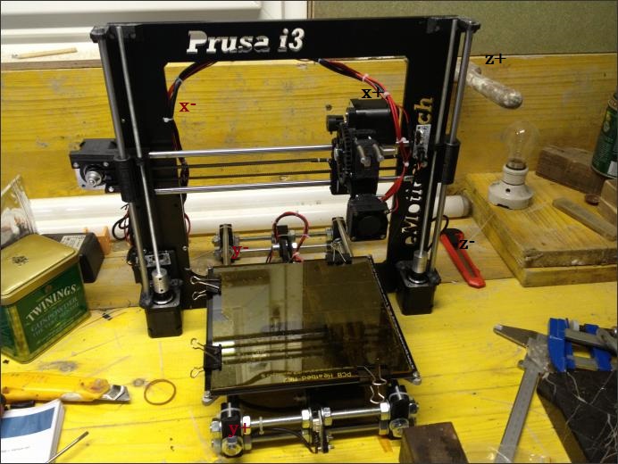
ok ma a me fa il contrario cioè se faccio fare la home premo + e viene verso di me premo - e si allontana leggendo le giude va al contrario pero se ribalto il motore va a fare la home dal lato opposto
allegata foto giusto per capire meglio se è cosi ma non credo oppure no
Edited 1 time(s). Last edit at 03/09/2014 02:03PM by fr4nc3sco.
|
Re: Aiuto inversione assi,endstop e configurazione home repetier e prima configurazione March 09, 2014 02:40PM |
Registered: 10 years ago Posts: 1,714 |
Lascia stare le guide: tu gli endstop li hai in Y- e X- (seguendo la foto). Se premi y+ il piatto si deve avvicinare a te, quindi va verso y max e se premi y- va verso l'endstop; l'home lo porta in y-
E' corretto così, non farti ingannare dal disegno di repetier-host
R2 Evo-Prometeo-Poseidon-Titan0
Multiextruder NPr3-WR4
[www.3dmakerlab.it]
E' corretto così, non farti ingannare dal disegno di repetier-host
R2 Evo-Prometeo-Poseidon-Titan0
Multiextruder NPr3-WR4
[www.3dmakerlab.it]
|
Re: Aiuto inversione assi,endstop e configurazione home repetier e prima configurazione March 10, 2014 05:01AM |
Registered: 10 years ago Posts: 447 |
Anch'io ho la stessa stampante, montata secondo la stessa guida.
Il motore Y è montato lato frontale (e non sul retro come fanno altri) e a destra rispetto alla metà della stampante, così come l'endstop y è frontale.
Quindi l'endstop è un Y min, premendo Y + il piatto si deve allontanare da te e andare verso il fondo e la direzione del motore Y deve essere la stessa del motore X. In entrambi i casi una rotazione antioraria del motore porta il valore x o y a crescere.
Mi pare che la rotazione antioraria sia il verso positivo di rotazione ma potrei sbagliarmi.
Prusa i3 Einstein rework ALU Frame - Arduino Mega 2560 + Ramps 1.4 - Stepsticks A4988 - Nema 17 - mechanical endstops - Wade's Extruder con Magma Hotend / 0.4mm nozzle - Hotbed con vetro e Kapton - Smart LCD 20x4 con rotary encoder
|
Re: Aiuto inversione assi,endstop e configurazione home repetier e prima configurazione March 10, 2014 05:48AM |
Registered: 10 years ago Posts: 350 |
Sì infatti io avendo motore ed endstop dal lato opposto la y la da dal lato contrario vedrò se no fa i pezzi specchiati poco male altrimenti faccio un nuovo endstop dal lato opposto in pratica la mia x0y0 resta in basso a sx mentre a te resta in alto a sinistra.... ora tanto ci sono altri problemi da risolvere sulla asse z ho perdite di passi
|
Re: Aiuto inversione assi,endstop e configurazione home repetier e prima configurazione March 10, 2014 06:15AM |
Registered: 10 years ago Posts: 447 |
Guarda, ho appena controllato e ho x/y/z come INVERT_#_DIR true/true/false.
Quindi la rotazione oraria (guardando di fronte il motore) è il verso positivo di rotazione.
Con piatto mobile, motore Y di fronte, cinghia al centro, corpo motore y sul lato destro l'INVERT_Y_DIR va true.
Per gli endstop x/y/z gli #_HOME_DIR tutti e tre - 1 (ovvero MIN).
Infine come valori di DEFAULT_AXIS_STEPS_PER_UNIT ho 80/80/4000/660.
L'ultimo dipende da quanto stringi le viti della pressa dell'estrusore.
Sorry, only registered users may post in this forum.