Home
>
RepRap User Groups
>
Europe
>
Italy RepRap User Group - Gruppo RepRap Italia
>
Elettronica e meccanica
>
Topic
BLTouch Minirambo wiring
Posted by jwg3
|
BLTouch Minirambo wiring May 14, 2018 12:19PM |
Registered: 5 years ago Posts: 1 |
This is an explanation of how to wire and configure a BLTouch (BLT) probe sensor for use with auto bed leveling compensation on a DIY 3D printer controlled by a Minirambo (MR) with Marlin 1.1.8 firmware.
To start, the Anticlabs documentation for the MR wiring and configuration is incorrect in most respects, and should be used only as a reference for controller board layout and some of the Marlin configuration. The main problem with the Antclabs instructions, are first, they were never tested as indicated on the diagram, and second, the MR has no extra PWM (Pulse Width Modulation) pins as documented on the MR Wiki page. These two facts mean you are starting from scratch to figure out the configuration.
Below is what I did to make the BLT work with the MR. As with any set of unofficial instructions (or even official ones), you are responsible for understanding and verifying correctness before proceeding with modifications.
Wiring:
The same two MR connectors as indicated by Anticlabs are used for BLT connections, ZMIN and ZMAX, but ZMIN is the only one of the two that has a PWM capable pin. To use it, Marlin must be reconfigured to remap the pins as explained here, [reprap.org] . The remapping moves the Zmin function to the ZMAX connector, sparing up the ZMIN connector and its PWM pin. In this case, I did the remapping in the pins_MINIRAMBO.h file like so:
//
// Limit Switches
//
#define X_MIN_PIN 12
#define X_MAX_PIN 30
#define Y_MIN_PIN 11
#define Y_MAX_PIN 24
#define Z_MIN_PIN 23 // ZMax's pin now used for ZMin. For BLTouch. - JWG
#define Z_MAX_PIN -1 // Moving ZMax pin to Z_MIN_PIN to make ZMin available for use as PWM servo pin. No Zmax in use; only ZMin using ZMax's pin. For BLTouch. - JWG
//
// Faux Servo for BLTouch
//
#define SERVO0_PIN 10 // ZMin pin used as PWM pin for BLTouch. Only MinEndstop pins can be used for PWM. - JWG
// Below, making sure pin 23 is not used as it is now Z_MINI_PIN for BLTouch. - JWG
// Z Probe (when not Z_MIN_PIN)
//
//#ifndef Z_MIN_PROBE_PIN
// #define Z_MIN_PROBE_PIN 23
//#endif
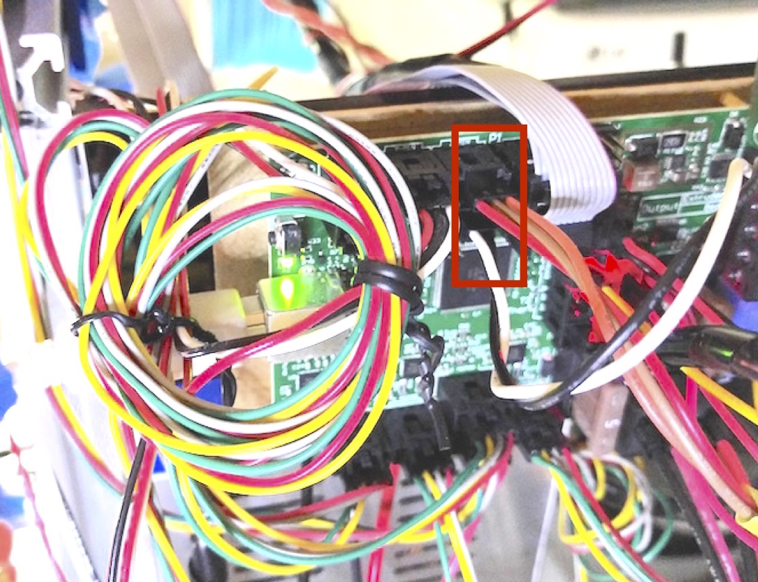
Please note from the MR board layout that the pins on ZMIN and ZMAX are in reverse order with respect to each other, so the cable connections have to be turned around (the orange wire will be on the right on ZMIN, and the white wire will be on the left on ZMAX).
Also, in Marlin's configuration.h, the #define Z_MIN_PROBE_USES_Z_MIN_ENDSTOP_PIN statement is not commented out. Not sure why, but it works with it defined, so I did not delve further into it. Marlin has a default preference for ZMAX, so that may be involved.
With the BLTouch wired and configured, it seems to work well and eliminates repetitive manual bed adjustments to keep the bed level. I have now removed the bed springs and adjuster wheels, and locked down the bed with standoffs and bolts, reducing ongoing maintenance.
To start, the Anticlabs documentation for the MR wiring and configuration is incorrect in most respects, and should be used only as a reference for controller board layout and some of the Marlin configuration. The main problem with the Antclabs instructions, are first, they were never tested as indicated on the diagram, and second, the MR has no extra PWM (Pulse Width Modulation) pins as documented on the MR Wiki page. These two facts mean you are starting from scratch to figure out the configuration.
Below is what I did to make the BLT work with the MR. As with any set of unofficial instructions (or even official ones), you are responsible for understanding and verifying correctness before proceeding with modifications.
Wiring:
The same two MR connectors as indicated by Anticlabs are used for BLT connections, ZMIN and ZMAX, but ZMIN is the only one of the two that has a PWM capable pin. To use it, Marlin must be reconfigured to remap the pins as explained here, [reprap.org] . The remapping moves the Zmin function to the ZMAX connector, sparing up the ZMIN connector and its PWM pin. In this case, I did the remapping in the pins_MINIRAMBO.h file like so:
//
// Limit Switches
//
#define X_MIN_PIN 12
#define X_MAX_PIN 30
#define Y_MIN_PIN 11
#define Y_MAX_PIN 24
#define Z_MIN_PIN 23 // ZMax's pin now used for ZMin. For BLTouch. - JWG
#define Z_MAX_PIN -1 // Moving ZMax pin to Z_MIN_PIN to make ZMin available for use as PWM servo pin. No Zmax in use; only ZMin using ZMax's pin. For BLTouch. - JWG
//
// Faux Servo for BLTouch
//
#define SERVO0_PIN 10 // ZMin pin used as PWM pin for BLTouch. Only MinEndstop pins can be used for PWM. - JWG
// Below, making sure pin 23 is not used as it is now Z_MINI_PIN for BLTouch. - JWG
// Z Probe (when not Z_MIN_PIN)
//
//#ifndef Z_MIN_PROBE_PIN
// #define Z_MIN_PROBE_PIN 23
//#endif
Please note from the MR board layout that the pins on ZMIN and ZMAX are in reverse order with respect to each other, so the cable connections have to be turned around (the orange wire will be on the right on ZMIN, and the white wire will be on the left on ZMAX).
Also, in Marlin's configuration.h, the #define Z_MIN_PROBE_USES_Z_MIN_ENDSTOP_PIN statement is not commented out. Not sure why, but it works with it defined, so I did not delve further into it. Marlin has a default preference for ZMAX, so that may be involved.
With the BLTouch wired and configured, it seems to work well and eliminates repetitive manual bed adjustments to keep the bed level. I have now removed the bed springs and adjuster wheels, and locked down the bed with standoffs and bolts, reducing ongoing maintenance.
|
Re: BLTouch Minirambo wiring March 05, 2020 09:20AM |
Registered: 7 years ago Posts: 3 |
Sorry, only registered users may post in this forum.