Home
>
RepRap User Groups
>
Europe
>
Italy RepRap User Group - Gruppo RepRap Italia
>
GCODE, Software e Firmware
>
Topic
Lo strano caso di X + 10= 3 mm e X -10 = 10mm..
Posted by mark2.cnc
|
Lo strano caso di X + 10= 3 mm e X -10 = 10mm.. September 10, 2015 12:43PM |
Registered: 9 years ago Posts: 92 |
Salve amici!
Ho appena assemblato un piccola Delta (o forse sarebbe più corretto dire un delta robot..) semplice semplice
ispirata ad un progetto trovato in rete chiamato TwinTeeth.
Arduino mega e ramps 1.4 (classico) niente Lcd e nessun extruder per ora.
Voglio solo vedere il movimento..
Prendo tutte le misure e compilo diligentemente tutto sul sito [marlinkimbra.it].
Carico il firmware e provo con repetier ad eseguire una semplice z da 10 (bottone) e si muove di circa 3 mm ma se premo il bottone opposto si abbassa di 10!
Strano vero?
Grazie a chi mi aiuterà!
|
Re: Lo strano caso di X + 10= 3 mm e X -10 = 10mm.. September 10, 2015 01:48PM |
Registered: 9 years ago Posts: 690 |
Ciao Mark,
non penso di poterti aiutare ma potresti allegare il firmware per facilitare le cose.
Potresti anche allegare una foto della delta, giusto per curiosità...comunque i delta robot dovrebbe essere altri ancora in teoria...
Delta Fluo --> Stampante Custom tipo Delta - IeC v4.0 0.4 - Ultratronics - MK4due 4.3.1 (dev)
|
Re: Lo strano caso di X + 10= 3 mm e X -10 = 10mm.. September 10, 2015 02:29PM |
Registered: 9 years ago Posts: 92 |
|
Re: Lo strano caso di X + 10= 3 mm e X -10 = 10mm.. September 10, 2015 02:30PM |
Registered: 9 years ago Posts: 92 |
configuration:
#ifndef CONFIGURATION_H #define CONFIGURATION_H // This configuration file contains basic settings. Select your: // - board type // - Mechanism type (cartesian-corexy-delta-scara) // - temperature sensor type // // Mechanisms-settings can be found in configuration_xxxxxx.h // Advanced settings can be found in Configuration_adv.h #include "boards.h" // Choose your board type. // Either an numeric ID or name defined in boards.h is valid. // See: [github.com] #define MOTHERBOARD BOARD_RAMPS_13_HFB // User-specified version info of this build to display in [Pronterface, etc] terminal window during // startup. Implementation of an idea by Prof Braino to inform user that any changes made to this // build by the user have been successfully uploaded into firmware. #define STRING_VERSION "4.1.2" #define STRING_URL "reprap.org" #define STRING_VERSION_CONFIG_H __DATE__ " " __TIME__ // build date and time #define STRING_CONFIG_H_AUTHOR "(none, default config)" // Who made the changes. #define STRING_SPLASH_LINE1 "v" STRING_VERSION // will be shown during bootup in line 1 #define STRING_SPLASH_LINE2 STRING_VERSION_CONFIG_H // will be shown during bootup in line 2 // SERIAL_PORT 0 // This allows the connection of wireless adapters (for instance) to non-default port pins. // Serial port 0 is still used by the Arduino bootloader regardless of this setting. #define SERIAL_PORT 0 // This determines the communication speed of the printer // 115200 - 250000 #define BAUDRATE 115200 // This enables the serial port associated to the Bluetooth interface on AT90USB devices //#define BTENABLED // Define this to set a unique identifier for this printer, (Used by some programs to differentiate between machines) // You can use an online service to generate a random UUID. (eg [www.uuidgenerator.net]) //#define MACHINE_UUID "00000000-0000-0000-0000-000000000000" // If you want test the firmware uncomment below. Use Serial arduino monitor... //#define FIRMWARE_TEST // ONLY BAUDRATE 115200 /***********************************************************************\ **************************** Define type printer ********************** ***********************************************************************/ //#define CARTESIAN //#define COREXY #define DELTA //#define SCARA /***********************************************************************\ /***********************************************************************\ ********************** Do not touch this section ********************** ***********************************************************************/ #if defined(CARTESIAN) #include "Configuration_Cartesian.h" #elif defined(COREXY) #include "Configuration_Core.h" #elif defined(DELTA) #include "Configuration_Delta.h" #elif defined(SCARA) #include "Configuration_Scara.h" #endif /***********************************************************************/ // This defines the number of extruder real or virtual #define EXTRUDERS 1 // This defines the number of Driver extruder you have and use #define DRIVER_EXTRUDERS 1 // This is used for single nozzle and multiple extrusion configuration // Uncomment below to enable (One Hotend) //#define SINGLENOZZLE /*********************************************************************** *********************** Multiextruder MKR4 *************************** *********************************************************************** * * * Setting for more extruder width relay system * * See pins.h for pin command relay * * * ***********************************************************************/ //#define MKR4 //********************************************************************** /*********************************************************************** *********************** Multiextruder NPr2 *************************** *********************************************************************** * * * Setting fot color meccanism NPr2 by NicolaP (www.3dmakerlab.it) * * Find angle setting by g-Code "M997 Cxxx" * * * ***********************************************************************/ //#define NPR2 #define COLOR_STEP {120,25,-65,-155} // CARTER ANGLE #define COLOR_SLOWRATE 170 // MICROSECOND delay for carter motor routine (Carter Motor Feedrate: upper value-slow feedrate) #define COLOR_HOMERATE 4 // FEEDRATE for carter home #define MOTOR_ANGLE 1.8 // Nema angle for single step #define DRIVER_MICROSTEP 4 // Microstep moltiplicator driver (set jumper MS1-2-3) off-on-off 1/4 microstepping. #define CARTER_MOLTIPLICATOR 14.22 // CARTER MOLTIPLICATOR (gear ratio 13/31-10/31) //********************************************************************** // The following define selects which power supply you have. Please choose the one that matches your setup // 0 = Normal power // 1 = ATX // 2 = X-Box 360 203 Watts (the blue wire connected to PS_ON and the red wire to VCC) #define POWER_SUPPLY 0 // Define this to have the electronics keep the power supply off on startup. If you don't know what this is leave it. //#define PS_DEFAULT_OFF //=========================================================================== //============================= Thermal Settings ============================ //=========================================================================== //================================ Thermistor =============================== //--NORMAL IS 4.7kohm PULLUP!-- 1kohm pullup can be used on hotend sensor, using correct resistor and table // //// Temperature sensor settings: // -2 is thermocouple with MAX6675 (only for sensor 0) // -1 is thermocouple with AD595 // 0 is not used // 1 is 100k thermistor - best choice for EPCOS 100k (4.7k pullup) // 2 is 200k thermistor - ATC Semitec 204GT-2 (4.7k pullup) // 3 is Mendel-parts thermistor (4.7k pullup) // 4 is 10k thermistor !! do not use it for a hotend. It gives bad resolution at high temp. !! // 5 is 100K thermistor - ATC Semitec 104GT-2 (Used in ParCan & J-Head) (4.7k pullup) // 6 is 100k EPCOS - Not as accurate as table 1 (created using a fluke thermocouple) (4.7k pullup) // 7 is 100k Honeywell thermistor 135-104LAG-J01 (4.7k pullup) // 71 is 100k Honeywell thermistor 135-104LAF-J01 (4.7k pullup) // 8 is 100k 0603 SMD Vishay NTCS0603E3104FXT (4.7k pullup) // 9 is 100k GE Sensing AL03006-58.2K-97-G1 (4.7k pullup) // 10 is 100k RS thermistor 198-961 (4.7k pullup) // 11 is 100k beta 3950 1% thermistor (4.7k pullup) // 12 is 100k 0603 SMD Vishay NTCS0603E3104FXT (4.7k pullup) (calibrated for Makibox hot bed) // 13 is 100k Hisens 3950 1% up to 300°C for hotend "Simple ONE " & "Hotend "All In ONE" // 20 is the PT100 circuit found in the Ultimainboard V2.x // 60 is 100k Maker's Tool Works Kapton Bed Thermistor beta=3950 // // 1k ohm pullup tables - This is not normal, you would have to have changed out your 4.7k for 1k // (but gives greater accuracy and more stable PID) // 51 is 100k thermistor - EPCOS (1k pullup) // 52 is 200k thermistor - ATC Semitec 204GT-2 (1k pullup) // 55 is 100k thermistor - ATC Semitec 104GT-2 (Used in ParCan & J-Head) (1k pullup) // // 1047 is Pt1000 with 4k7 pullup // 1010 is Pt1000 with 1k pullup (non standard) // 147 is Pt100 with 4k7 pullup // 110 is Pt100 with 1k pullup (non standard) // 998 and 999 are Dummy Tables. They will ALWAYS read 25°C or the temperature defined below. // Use it for Testing or Development purposes. NEVER for production machine. // #define DUMMY_THERMISTOR_998_VALUE 25 // #define DUMMY_THERMISTOR_999_VALUE 100 #define TEMP_SENSOR_0 0 #define TEMP_SENSOR_1 0 #define TEMP_SENSOR_2 0 #define TEMP_SENSOR_3 0 #define TEMP_SENSOR_BED 1 // This makes temp sensor 1 a redundant sensor for sensor 0. If the temperatures difference between these sensors is to high the print will be aborted. //#define TEMP_SENSOR_1_AS_REDUNDANT #define MAX_REDUNDANT_TEMP_SENSOR_DIFF 10 // (degC) // Actual temperature must be close to target for this long before M109 returns success #define TEMP_RESIDENCY_TIME 10 // (seconds) #define TEMP_HYSTERESIS 3 // (degC) range of +/- temperatures considered "close" to the target one #define TEMP_WINDOW 1 // (degC) Window around target to start the residency timer x degC early. // The minimal temperature defines the temperature below which the heater will not be enabled It is used // to check that the wiring to the thermistor is not broken. // Otherwise this would lead to the heater being powered on all the time. #define HEATER_0_MINTEMP 5 // (degC) #define HEATER_1_MINTEMP 5 // (degC) #define HEATER_2_MINTEMP 5 // (degC) #define HEATER_3_MINTEMP 5 // (degC) #define BED_MINTEMP 5 // (degC) // When temperature exceeds max temp, your heater will be switched off. // This feature exists to protect your hotend from overheating accidentally, but *NOT* from thermistor short/failure! // You should use MINTEMP for thermistor short/failure protection. #define HEATER_0_MAXTEMP 275 // (degC) #define HEATER_1_MAXTEMP 275 // (degC) #define HEATER_2_MAXTEMP 275 // (degC) #define HEATER_3_MAXTEMP 275 // (degC) #define BED_MAXTEMP 150 // (degC) // If your bed has low resistance e.g. .6 ohm and throws the fuse you can duty cycle it to reduce the // average current. The value should be an integer and the heat bed will be turned on for 1 interval of // HEATER_BED_DUTY_CYCLE_DIVIDER intervals. //#define HEATER_BED_DUTY_CYCLE_DIVIDER 4 // If you want the M105 heater power reported in watts, define the BED_WATTS, and (shared for all hotend) HOTEND_WATTS //#define HOTEND_WATTS (12.0*12.0/6.7) // P=I^2/R //#define BED_WATTS (12.0*12.0/1.1) // P=I^2/R //=========================================================================== //============================= PID Settings ================================ //=========================================================================== // PID Tuning Guide here: [reprap.org] // Comment the following line to disable PID and enable bang-bang. #define PIDTEMP #define BANG_MAX 255 // limits current to nozzle while in bang-bang mode; 255=full current #define PID_MAX BANG_MAX // limits current to nozzle while PID is active (see PID_FUNCTIONAL_RANGE below); 255=full current //#define PID_DEBUG // Sends debug data to the serial port. //#define PID_OPENLOOP 1 // Puts PID in open loop. M104/M140 sets the output power from 0 to PID_MAX //#define SLOW_PWM_HEATERS // PWM with very low frequency (roughly 0.125Hz=8s) and minimum state time of approximately 1s useful for heaters driven by a relay // If the temperature difference between the target temperature and the actual temperature // is more then PID_FUNCTIONAL_RANGE then the PID will be shut off and the heater will be set to min/max. #define PID_FUNCTIONAL_RANGE 10 // degC #define PID_INTEGRAL_DRIVE_MAX PID_MAX // Limit for the integral term #define K1 0.95 // Smoothing factor within the PID // HotEnd{HE0,HE1,HE2,HE3} #define DEFAULT_Kp {41.51,41.51,41.51,41.51} // Kp for E0, E1, E2, E3 #define DEFAULT_Ki {7.28,7.28,7.28,7.28} // Ki for E0, E1, E2, E3 #define DEFAULT_Kd {59.17,59.17,59.17,59.17} // Kd for E0, E1, E2, E3 //=========================================================================== //=========================================================================== //============================= PID > Bed Temperature Control =============== //=========================================================================== // Select PID or bang-bang with PIDTEMPBED. If bang-bang, BED_LIMIT_SWITCHING will enable hysteresis // // Uncomment this to enable PID on the bed. It uses the same frequency PWM as the extruder. // If your PID_dT is the default, and correct for your hardware/configuration, that means 7.689Hz, // which is fine for driving a square wave into a resistive load and does not significantly impact you FET heating. // This also works fine on a Fotek SSR-10DA Solid State Relay into a 250W heater. // If your configuration is significantly different than this and you don't understand the issues involved, you probably // shouldn't use bed PID until someone else verifies your hardware works. // If this is enabled, find your own PID constants below. //#define PIDTEMPBED // //#define BED_LIMIT_SWITCHING // This sets the max power delivered to the bed, and replaces the HEATER_BED_DUTY_CYCLE_DIVIDER option. // all forms of bed control obey this (PID, bang-bang, bang-bang with hysteresis) // setting this to anything other than 255 enables a form of PWM to the bed just like HEATER_BED_DUTY_CYCLE_DIVIDER did, // so you shouldn't use it unless you are OK with PWM on your bed. (see the comment on enabling PIDTEMPBED) #define MAX_BED_POWER 255 // limits duty cycle to bed; 255=full current //#define PID_BED_DEBUG // Sends debug data to the serial port. //120v 250W silicone heater into 4mm borosilicate (MendelMax 1.5+) //from FOPDT model - kp=.39 Tp=405 Tdead=66, Tc set to 79.2, aggressive factor of .15 (vs .1, 1, 10) #define DEFAULT_bedKp 10.00 #define DEFAULT_bedKi .023 #define DEFAULT_bedKd 305.4 //120v 250W silicone heater into 4mm borosilicate (MendelMax 1.5+) //from pidautotune // #define DEFAULT_bedKp 97.1 // #define DEFAULT_bedKi 1.41 // #define DEFAULT_bedKd 1675.16 // FIND YOUR OWN: "M303 E-1 C8 S90" to run autotune on the bed at 90 degreesC for 8 cycles. //=========================================================================== //this prevents dangerous Extruder moves, i.e. if the temperature is under the limit //can be software-disabled for whatever purposes by #define PREVENT_DANGEROUS_EXTRUDE //if PREVENT DANGEROUS EXTRUDE is on, you can still disable (uncomment) very long bits of extrusion separately. #define PREVENT_LENGTHY_EXTRUDE #define EXTRUDE_MINTEMP 170 // degC #define EXTRUDE_MAXLENGTH (X_MAX_LENGTH+Y_MAX_LENGTH) //prevent extrusion of very large distances. //=========================================================================== //======================== Thermal Runaway Protection ======================= //=========================================================================== /** * Thermal Runaway Protection protects your printer from damage and fire if a * thermistor falls out or temperature sensors fail in any way. * * The issue: If a thermistor falls out or a temperature sensor fails, * Marlin can no longer sense the actual temperature. Since a disconnected * thermistor reads as a low temperature, the firmware will keep the heater on. * * The solution: Once the temperature reaches the target, start observing. * If the temperature stays too far below the target (hysteresis) for too long, * the firmware will halt as a safety precaution. * * Note that because the countdown starts only AFTER the temperature reaches * the target, this will not catch a thermistor that is already disconnected * when the print starts! * * To enable for all extruder heaters, uncomment the two defines below: */ // Parameters for all extruder heaters #define THERMAL_RUNAWAY_PROTECTION_PERIOD 40 // in seconds #define THERMAL_RUNAWAY_PROTECTION_HYSTERESIS 4 // in degree Celsius // To enable for the bed heater, uncomment the two defines below: // Parameters for the bed heater #define THERMAL_RUNAWAY_PROTECTION_BED_PERIOD 20 // in seconds #define THERMAL_RUNAWAY_PROTECTION_BED_HYSTERESIS 2 // in degree Celsius //=========================================================================== //============================ User Interfaces ============================== //=========================================================================== //==============================LCD and SD support============================= // Choose ONE of these 3 charsets. This has to match your hardware. Ignored for full graphic display. // To find out what type you have - compile with (test) - upload - click to get the menu. You'll see two typical lines from the upper half of the charset. // See also documentation/LCDLanguageFont.md #define DISPLAY_CHARSET_HD44780_JAPAN // this is the most common hardware //#define DISPLAY_CHARSET_HD44780_WESTERN //#define DISPLAY_CHARSET_HD44780_CYRILLIC //#define ULTRA_LCD //general LCD support, also 16x2 //#define DOGLCD // Support for SPI LCD 128x64 (Controller ST7565R graphic Display Family) //#define SDSUPPORT // Enable SD Card Support in Hardware Console //#define SDSLOW // Use slower SD transfer mode (not normally needed - uncomment if you're getting volume init error) //#define SD_CHECK_AND_RETRY // Use CRC checks and retries on the SD communication //#define ENCODER_PULSES_PER_STEP 1 // Increase if you have a high resolution encoder //#define ENCODER_STEPS_PER_MENU_ITEM 5 // Set according to ENCODER_PULSES_PER_STEP or your liking //#define ULTIMAKERCONTROLLER //as available from the Ultimaker online store. //#define ULTIPANEL //the UltiPanel as on Thingiverse //#define LCD_FEEDBACK_FREQUENCY_DURATION_MS 100 // the duration the buzzer plays the UI feedback sound. ie Screen Click //#define LCD_FEEDBACK_FREQUENCY_HZ 1000 // this is the tone frequency the buzzer plays when on UI feedback. ie Screen Click // 0 to disable buzzer feedback. Test with M300 S P // PanelOne from T3P3 (via RAMPS 1.4 AUX2/AUX3) // [reprap.org] //#define PANEL_ONE // The MaKr3d Makr-Panel with graphic controller and SD support // [reprap.org] //#define MAKRPANEL // The Panucatt Devices Viki 2.0 and mini Viki with Graphic LCD // [panucatt.com] // ==> REMEMBER TO INSTALL U8glib to your ARDUINO library folder: [code.google.com] //#define VIKI2 //#define miniVIKI // The RepRapDiscount Smart Controller (white PC// [reprap.org] //#define REPRAP_DISCOUNT_SMART_CONTROLLER // The GADGETS3D G3D LCD/SD Controller (blue PC
|
Re: Lo strano caso di X + 10= 3 mm e X -10 = 10mm.. September 10, 2015 02:31PM |
Registered: 9 years ago Posts: 92 |
// Define this to set a custom name for your generic Delta
// Displayed in the LCD "Ready" message
#define CUSTOM_MACHINE_NAME "deltah"

//===========================================================================
//============================== Delta Settings =============================
//===========================================================================

// Make delta curves from many straight lines (linear interpolation).
// This is a trade-off between visible corners (not enough segments)
// and processor overload (too many expensive sqrt calls).
#define DELTA_SEGMENTS_PER_SECOND 200

// Center-to-center distance of the holes in the diagonal push rods.
#define DEFAULT_DELTA_DIAGONAL_ROD 158     // mm

// Horizontal offset from middle of printer to smooth rod center.
#define DELTA_SMOOTH_ROD_OFFSET 125.6      // mm

// Horizontal offset of the universal joints on the end effector.
#define DELTA_EFFECTOR_OFFSET 26.4     // mm

// Horizontal offset of the universal joints on the carriages.
#define DELTA_CARRIAGE_OFFSET 19.2      // mm

// Bed Printer radius
#define PRINTER_RADIUS 75      // mm

//Uncomment to enable autocalibration debug messages
#define DEBUG_MESSAGES

// Precision for G30 delta autocalibration function
#define AUTOCALIBRATION_PRECISION 0.1      // mm

// Effective horizontal distance bridged by diagonal push rods.
#define DEFAULT_DELTA_RADIUS (DELTA_SMOOTH_ROD_OFFSET-DELTA_EFFECTOR_OFFSET-DELTA_CARRIAGE_OFFSET)

// Z-Probe variables
// Start and end location values are used to deploy/retract the probe (will move from start to end and back again)
#define PROBING_FEEDRATE 100                          // Speed for individual probe Use: G30 A F600
#define Z_PROBE_OFFSET {0,0,-10}      // X, Y, Z, E distance between hotend nozzle and deployed bed leveling probe.
#define Z_PROBE_DEPLOY_START_LOCATION {0,0,30,0}      // X, Y, Z, E start location for z-probe deployment sequence
#define Z_PROBE_DEPLOY_END_LOCATION {0,0,0,0}      // X, Y, Z, E end location for z-probe deployment sequence
#define Z_PROBE_RETRACT_START_LOCATION {0,0,30,0}      // X, Y, Z, E start location for z-probe retract sequence
#define Z_PROBE_RETRACT_END_LOCATION {0,0,0,0}      // X, Y, Z, E end location for z-probe retract sequence
#define Z_RAISE_BETWEEN_PROBINGS 2                    // How much the extruder will be raised when travelling from between next probing points
#define AUTOLEVEL_GRID 20      // Distance between autolevel Z probing points, should be less than print surface radius/3.

//===========================================================================
//=============================Mechanical Settings===========================
//===========================================================================

// coarse Endstop Settings
//#define ENDSTOPPULLUPS // Comment this out (using // at the start of the line) to disable the endstop pullup resistors

#ifndef ENDSTOPPULLUPS
  // fine endstop settings: Individual pullups. will be ignored if ENDSTOPPULLUPS is defined
 #define ENDSTOPPULLUP_XMAX
 #define ENDSTOPPULLUP_YMAX
 #define ENDSTOPPULLUP_ZMAX
 #define ENDSTOPPULLUP_XMIN
 #define ENDSTOPPULLUP_YMIN
 #define ENDSTOPPULLUP_ZMIN
 #define ENDSTOPPULLUP_ZPROBE
 #define ENDSTOPPULLUP_EMIN
#endif

// Mechanical endstop with COM to ground and NC to Signal uses "false" here (most common setup).
#define X_MIN_ENDSTOP_LOGIC false      // set to true to invert the logic of the endstop.
#define Y_MIN_ENDSTOP_LOGIC false      // set to true to invert the logic of the endstop.
#define Z_MIN_ENDSTOP_LOGIC false      // set to true to invert the logic of the endstop.
#define E_MIN_ENDSTOP_LOGIC false      // set to true to invert the logic of the endstop.
#define X_MAX_ENDSTOP_LOGIC false      // set to true to invert the logic of the endstop.
#define Y_MAX_ENDSTOP_LOGIC false      // set to true to invert the logic of the endstop.
#define Z_MAX_ENDSTOP_LOGIC false      // set to true to invert the logic of the endstop.
#define Z_PROBE_ENDSTOP_LOGIC false      // set to true to invert the logic of the endstop.
// If you want to enable the Z Probe pin, but disable its use, uncomment the line below.
// Z_PROBE_ENDSTOP must are active if you want Autocalibration
#define Z_PROBE_ENDSTOP

// ENDSTOP SETTINGS:
// Sets direction of endstop when homing; 1=MAX, -1=MIN
#define X_HOME_DIR 1      // MUST HAVE MAX ENDSTOP
#define Y_HOME_DIR 1      // MUST HAVE MAX ENDSTOP
#define Z_HOME_DIR 1      // MUST HAVE MAX ENDSTOP

#define min_software_endstops true  // If true, axis won't move to coordinates less than HOME_POS.
#define max_software_endstops true  // If true, axis won't move to coordinates greater than the defined lengths below.


// For Inverting Stepper Enable Pins (Active Low) use 0, Non Inverting (Active High) use 1
#define X_ENABLE_ON 0
#define Y_ENABLE_ON 0
#define Z_ENABLE_ON 0
#define E_ENABLE_ON 0      // For all extruder

// Disables axis when it's not being used.
#define DISABLE_X false
#define DISABLE_Y false
#define DISABLE_Z false
#define DISABLE_E false      // For all extruder
#define DISABLE_INACTIVE_EXTRUDER false //disable only inactive extruder and keep active extruder enabled

// If you motor turns to wrong direction, you can invert it here:
#define INVERT_X_DIR false
#define INVERT_Y_DIR false
#define INVERT_Z_DIR false
#define INVERT_E0_DIR false
#define INVERT_E1_DIR false
#define INVERT_E2_DIR false
#define INVERT_E3_DIR false

// The position of the homing switches
#define MANUAL_HOME_POSITIONS  // If defined, MANUAL_*_HOME_POS below will be used
#define BED_CENTER_AT_0_0      // If defined, the center of the bed is at (X=0, Y=0)

//Manual homing switch locations:
#define MANUAL_X_HOME_POS 0
#define MANUAL_Y_HOME_POS 0
#define MANUAL_Z_HOME_POS 210      // Distance between nozzle and print surface after homing.

// Travel limits after homing (units are in mm)
#define X_MAX_POS PRINTER_RADIUS
#define X_MIN_POS -PRINTER_RADIUS
#define Y_MAX_POS PRINTER_RADIUS
#define Y_MIN_POS -PRINTER_RADIUS
#define Z_MAX_POS MANUAL_Z_HOME_POS
#define Z_MIN_POS 0
#define E_MIN_POS 0


// MOVEMENT SETTINGS
#define HOMING_FEEDRATE {100*60,100*60,100*60,0}      // set the homing speeds (mm/min)

// default settings
// delta speeds must be the same on xyz
#define DEFAULT_AXIS_STEPS_PER_UNIT {100,100,100,625,625,625,625}      // X, Y, Z, E0, E1, E2, E3
#define DEFAULT_MAX_FEEDRATE {530,530,530,100,100,100,100}      // X, Y, Z, E0, E1, E2, E3 (mm/sec)
#define DEFAULT_RETRACTION_MAX_FEEDRATE {150,150,150,150}      // E0, E1, E2, E3 (mm/sec)
#define DEFAULT_MAX_ACCELERATION {3000,3000,3000,3000,3000,3000,3000}      // X, Y, Z, E0, E1, E2, E3 maximum start speed for accelerated moves.

#define DEFAULT_ACCELERATION 2500      // X, Y, Z and E max acceleration in mm/s^2 for printing moves
#define DEFAULT_RETRACT_ACCELERATION 10000      // X, Y, Z and E max acceleration in mm/s^2 for retracts
#define DEFAULT_TRAVEL_ACCELERATION 3000      // X, Y, Z acceleration in mm/s^2 for travel (non printing) moves

// Offset of the extruders (uncomment if using more than one and relying on firmware to position when changing).
// The offset has to be X=0, Y=0 for the extruder 0 hotend (default extruder).
// For the other hotends it is their distance from the extruder 0 hotend.
//#define HOTEND_OFFSET_X {0.0, 5.00, 0.0, 0.0} // (in mm) for each extruder, offset of the hotend on the X axis
//#define HOTEND_OFFSET_Y {0.0, 5.00, 0.0, 0.0} // (in mm) for each extruder, offset of the hotend on the Y axis

// The speed change that does not require acceleration (i.e. the software might assume it can be done instantaneously)
#define DEFAULT_XYJERK 10      // (mm/sec)
#define DEFAULT_ZJERK 10      // (mm/sec)
#define DEFAULT_EJERK 5      // (mm/sec)
|
Re: Lo strano caso di X + 10= 3 mm e X -10 = 10mm.. September 10, 2015 02:38PM |
Registered: 9 years ago Posts: 92 |

|
Re: Lo strano caso di X + 10= 3 mm e X -10 = 10mm.. September 11, 2015 02:42AM |
Registered: 9 years ago Posts: 92 |

|
Re: Lo strano caso di X + 10= 3 mm e X -10 = 10mm.. September 11, 2015 03:03AM |
Registered: 10 years ago Posts: 6,409 |
La home la fa bene?
Lato fw mi sembra tutto ok... Non vorrei che hai una vref bassa e i motori perdono passi in salita...
COMPRA ITALIANO - sostieni le nostre aziende - sostieni la nostra gente - sostieni il tuo popolo - sosterrai te stesso.
Alberto C. felice possessore di una Kossel K2
My Blog - My Thingiverse
Lato fw mi sembra tutto ok... Non vorrei che hai una vref bassa e i motori perdono passi in salita...
COMPRA ITALIANO - sostieni le nostre aziende - sostieni la nostra gente - sostieni il tuo popolo - sosterrai te stesso.
Alberto C. felice possessore di una Kossel K2
My Blog - My Thingiverse
|
Re: Lo strano caso di X + 10= 3 mm e X -10 = 10mm.. September 11, 2015 03:59AM |
Registered: 9 years ago Posts: 92 |
|
Re: Lo strano caso di X + 10= 3 mm e X -10 = 10mm.. September 11, 2015 04:47AM |
Registered: 9 years ago Posts: 92 |
|
Re: Lo strano caso di X + 10= 3 mm e X -10 = 10mm.. September 11, 2015 04:53AM |
Registered: 9 years ago Posts: 92 |

|
Re: Lo strano caso di X + 10= 3 mm e X -10 = 10mm.. September 11, 2015 05:25AM |
Registered: 10 years ago Posts: 6,409 |
Cioè fammi capire??? Che vuol dire fai l'homing e poi dai il comando +10 e comincia a salire, come fa se è già in homing????
COMPRA ITALIANO - sostieni le nostre aziende - sostieni la nostra gente - sostieni il tuo popolo - sosterrai te stesso.
Alberto C. felice possessore di una Kossel K2
My Blog - My Thingiverse
COMPRA ITALIANO - sostieni le nostre aziende - sostieni la nostra gente - sostieni il tuo popolo - sosterrai te stesso.
Alberto C. felice possessore di una Kossel K2
My Blog - My Thingiverse
|
Re: Lo strano caso di X + 10= 3 mm e X -10 = 10mm.. September 11, 2015 06:12AM |
Registered: 9 years ago Posts: 92 |
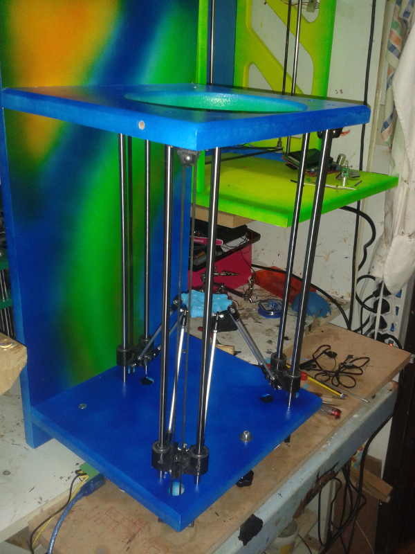
Considera come si vede dalla foto che la macchina è costruita upside down
secondo la filosofia dell' autore di twin-teeth (il bambino può lavare i suoi due incisivi
muovendo lo spazzolino e tenendo la testa ferma oppure tenendo il braccio fermo e
muovendo la testa!).
comunque dopo aver premuto gli switch si ferma
dopo di che qualsiasi bottone prema per l' asse Z (repetier) l' effector "sale" di circa 6/7 centimetri.
poi se avvio sale ancora fino allo 0 (che è in alto x me)..
Edited 1 time(s). Last edit at 09/11/2015 06:45AM by mark2.cnc.
|
Re: Lo strano caso di X + 10= 3 mm e X -10 = 10mm.. September 19, 2015 01:19PM |
Registered: 9 years ago Posts: 92 |
Sorry, only registered users may post in this forum.