Home
>
Safety & Best Practices
>
Topic
terminal got burnt
Posted by sarf2k4
|
terminal got burnt April 23, 2015 10:13PM |
Registered: 9 years ago Posts: 476 |
Hi, I wanted to ask you guys about this problem, I got my terminal connection burnt last night after about 4 stressful print in total of about 15 hours I think. Last night when I tried to heat the bed, it suddenly turned off when it reaches 70'c. I believe I am using a 10awg wire; quite sturdy wire with a diameter of around 2.5mm (copper).
The board has little solder plate left (place to connect the joints using solder irons), and I am planning to solder the wire directly to the board tomorrow with the help of my friend, I am not sure if it is still usable to solder the wire on to it. I am running on 12v system and I believe the mosfet/terminal unable to handle 15a current. But mine was different from this guy here while referring to this site makes me confused with the terms in the table
I got few questions:
Regards
-Sarf
The board has little solder plate left (place to connect the joints using solder irons), and I am planning to solder the wire directly to the board tomorrow with the help of my friend, I am not sure if it is still usable to solder the wire on to it. I am running on 12v system and I believe the mosfet/terminal unable to handle 15a current. But mine was different from this guy here while referring to this site makes me confused with the terms in the table
I got few questions:
- Does household cable (neutral,live,earth, the one with blue, brown, yellow stripe green) can be used for 15-20a current?
- Is there a reference to a wire gauge and their rated current specifications?
- Was it my wrong cable selection of this 10awg, a hard cable that has memory effect when bent?
- Will the board still usable?
Regards
-Sarf
|
Re: terminal got burnt April 24, 2015 02:47AM |
Registered: 9 years ago Posts: 30 |
Quote
sarf2k4
Hi, I wanted to ask you guys about this problem, I got my terminal connection burnt last night after about 4 stressful print in total of about 15 hours I think. Last night when I tried to heat the bed, it suddenly turned off when it reaches 70'c. I believe I am using a 10awg wire; quite sturdy wire with a diameter of around 2.5mm (copper).
The board has little solder plate left (place to connect the joints using solder irons), and I am planning to solder the wire directly to the board tomorrow with the help of my friend, I am not sure if it is still usable to solder the wire on to it. I am running on 12v system and I believe the mosfet/terminal unable to handle 15a current. But mine was different from this guy here while referring to this site makes me confused with the terms in the table
I got few questions:
- Does household cable (neutral,live,earth, the one with blue, brown, yellow stripe green) can be used for 15-20a current?
- Is there a reference to a wire gauge and their rated current specifications?
- Was it my wrong cable selection of this 10awg, a hard cable that has memory effect when bent?
- Will the board still usable?
Regards
-Sarf
That doesn't look to me like a problem with your choice of wire size but rather with the connection of the wire to the board or possibly with the type of wire. Assuming you used multi stranded flexible wire "flex", either the soldering of the connector to the board was poor and offered a high resistance (google "dry joint") or the connection of the wire into the connector was high resistance. That could be because you trapped some insulation in there so there was only a very small contact area of actual copper, or the copper was dirty/tarnished or you didn't do the screws up tightly.
On the other hand your phrase "a hard cable that has memory effect when bent" rings an alarm bell. Assuming your bed moves then you *must* use a multi-stranded flexible cable. If you used a solid cored mains fixed wiring cable then after a while the single cores will start to break and as that happens they will offer a high resistance and get hot at the bend point. It looks to me as if that could be your problem. Perhaps you could post a photo of the wire you used. Even better if you still have the burned bit - that should tell us a lot.
Your board is probably salvagable but it will take some care. I would solder in a new connector then solder a wire from each pin of the connector to wherever it tracks to on the PCB. Also look for how well it is now mechanically supported and possibly give it some more support with glue.
I'm really not trying to be insulting but you might perhaps want to get some soldering practice on a board you don't care about first as you are risking doing more damage as you try to repair it. Try to use a more powerful soldering iron so that the solder melts cleanly and the task can be done quickly. Make sure the solder is properly and fully melted before you try to move the component. Get hold of some flux (a flux pen works well) or as an alternative add some new solder before removing the old (the new solder contains flux). To be fair, power connections are the hardest to solder because of all the copper sucking the heat away.
Good luck with this,
Calvin
|
Re: terminal got burnt April 24, 2015 03:06AM |
Registered: 9 years ago Posts: 476 |
I will post a picture about the cable I used, it is a multi-stranded cable with about 7 strands and not too flexible. I believe I already clipped that burnt tip apart down to the bin.Quote
csambrook
Quote
sarf2k4
Hi, I wanted to ask you guys about this problem, I got my terminal connection burnt last night after about 4 stressful print in total of about 15 hours I think. Last night when I tried to heat the bed, it suddenly turned off when it reaches 70'c. I believe I am using a 10awg wire; quite sturdy wire with a diameter of around 2.5mm (copper).
The board has little solder plate left (place to connect the joints using solder irons), and I am planning to solder the wire directly to the board tomorrow with the help of my friend, I am not sure if it is still usable to solder the wire on to it. I am running on 12v system and I believe the mosfet/terminal unable to handle 15a current. But mine was different from this guy here while referring to this site makes me confused with the terms in the table
I got few questions:
- Does household cable (neutral,live,earth, the one with blue, brown, yellow stripe green) can be used for 15-20a current?
- Is there a reference to a wire gauge and their rated current specifications?
- Was it my wrong cable selection of this 10awg, a hard cable that has memory effect when bent?
- Will the board still usable?
Regards
-Sarf
That doesn't look to me like a problem with your choice of wire size but rather with the connection of the wire to the board or possibly with the type of wire. Assuming you used multi stranded flexible wire "flex", either the soldering of the connector to the board was poor and offered a high resistance (google "dry joint") or the connection of the wire into the connector was high resistance. That could be because you trapped some insulation in there so there was only a very small contact area of actual copper, or the copper was dirty/tarnished or you didn't do the screws up tightly.
On the other hand your phrase "a hard cable that has memory effect when bent" rings an alarm bell. Assuming your bed moves then you *must* use a multi-stranded flexible cable. If you used a solid cored mains fixed wiring cable then after a while the single cores will start to break and as that happens they will offer a high resistance and get hot at the bend point. It looks to me as if that could be your problem. Perhaps you could post a photo of the wire you used. Even better if you still have the burned bit - that should tell us a lot.
Your board is probably salvagable but it will take some care. I would solder in a new connector then solder a wire from each pin of the connector to wherever it tracks to on the PCB. Also look for how well it is now mechanically supported and possibly give it some more support with glue.
I'm really not trying to be insulting but you might perhaps want to get some soldering practice on a board you don't care about first as you are risking doing more damage as you try to repair it. Try to use a more powerful soldering iron so that the solder melts cleanly and the task can be done quickly. Make sure the solder is properly and fully melted before you try to move the component. Get hold of some flux (a flux pen works well) or as an alternative add some new solder before removing the old (the new solder contains flux). To be fair, power connections are the hardest to solder because of all the copper sucking the heat away.
Good luck with this,
Calvin
I do admit I'm pretty bad at soldering as I have started soldering a bit recently for about a month ago, the joint was well last night, it was the wire that snapped, not on the soldered joints.
I bought this wire I thought it would be perfect and able to support 20a current rather than the household appliance cable (I thought just 13-15a) current, then I crimped it to a fork terminal (that looked like wishbone) because the cable perfectly fit to that wishbone terminal
So, uhm, does the home appliance cable can be used?
Regards
-Sarf
|
Re: terminal got burnt April 24, 2015 04:21AM |
Registered: 9 years ago Posts: 30 |
Quote
sarf2k4
I will post a picture about the cable I used, it is a multi-stranded cable with about 7 strands and not too flexible. I believe I already clipped that burnt tip apart down to the bin.Quote
csambrook
Quote
sarf2k4
Hi, I wanted to ask you guys about this problem, I got my terminal connection burnt last night after about 4 stressful print in total of about 15 hours I think. Last night when I tried to heat the bed, it suddenly turned off when it reaches 70'c. I believe I am using a 10awg wire; quite sturdy wire with a diameter of around 2.5mm (copper).
The board has little solder plate left (place to connect the joints using solder irons), and I am planning to solder the wire directly to the board tomorrow with the help of my friend, I am not sure if it is still usable to solder the wire on to it. I am running on 12v system and I believe the mosfet/terminal unable to handle 15a current. But mine was different from this guy here while referring to this site makes me confused with the terms in the table
I got few questions:
- Does household cable (neutral,live,earth, the one with blue, brown, yellow stripe green) can be used for 15-20a current?
- Is there a reference to a wire gauge and their rated current specifications?
- Was it my wrong cable selection of this 10awg, a hard cable that has memory effect when bent?
- Will the board still usable?
Regards
-Sarf
That doesn't look to me like a problem with your choice of wire size but rather with the connection of the wire to the board or possibly with the type of wire. Assuming you used multi stranded flexible wire "flex", either the soldering of the connector to the board was poor and offered a high resistance (google "dry joint") or the connection of the wire into the connector was high resistance. That could be because you trapped some insulation in there so there was only a very small contact area of actual copper, or the copper was dirty/tarnished or you didn't do the screws up tightly.
On the other hand your phrase "a hard cable that has memory effect when bent" rings an alarm bell. Assuming your bed moves then you *must* use a multi-stranded flexible cable. If you used a solid cored mains fixed wiring cable then after a while the single cores will start to break and as that happens they will offer a high resistance and get hot at the bend point. It looks to me as if that could be your problem. Perhaps you could post a photo of the wire you used. Even better if you still have the burned bit - that should tell us a lot.
Your board is probably salvagable but it will take some care. I would solder in a new connector then solder a wire from each pin of the connector to wherever it tracks to on the PCB. Also look for how well it is now mechanically supported and possibly give it some more support with glue.
I'm really not trying to be insulting but you might perhaps want to get some soldering practice on a board you don't care about first as you are risking doing more damage as you try to repair it. Try to use a more powerful soldering iron so that the solder melts cleanly and the task can be done quickly. Make sure the solder is properly and fully melted before you try to move the component. Get hold of some flux (a flux pen works well) or as an alternative add some new solder before removing the old (the new solder contains flux). To be fair, power connections are the hardest to solder because of all the copper sucking the heat away.
Good luck with this,
Calvin
I do admit I'm pretty bad at soldering as I have started soldering a bit recently for about a month ago, the joint was well last night, it was the wire that snapped, not on the soldered joints.
I bought this wire I thought it would be perfect and able to support 20a current rather than the household appliance cable (I thought just 13-15a) current, then I crimped it to a fork terminal (that looked like wishbone) because the cable perfectly fit to that wishbone terminal
So, uhm, does the home appliance cable can be used?
Regards
-Sarf
I look forward to pictures of the cable. Too stiff a cable can be an issue but from your description I wonder if the crimp joint may have been the problem. Clearly the overheating was quite localised and near the connector or inside it. Crimp joints can be deceptively hard to make properly without specialist tools and for this application you are asking quite a lot of the joint, 20A is not trivial. The cheap crimp tools you can get in DIY shops are fairly rubbish and simply crush the connector onto the wire which can result in a joint with quite a small contact area, worse it is difficult to inspect to be sure it's good. Proper crimp tools (expensive) control the shape of the crimp to ensure good contact area which is vital at high currents. Personally, for this application, if I was using a cheap crimp tool I'd be tempted to also run some solder into the joint as well.
I'm not sure if home appliance flex could be used - I've not thought about it very much. My guess is that it would be absolutely fine and to be honest if I was doing this at home for myself I'd probably get hold of some "extra flexible" 13A mains cable, sometimes called "arctic cable". Although it's called "13A" it's actually capable of much more, the circuit is fused at 13A for safety. Current ratings for cable are a little odd anyway, they're a bit of a shorthand, it's really a calculation involving how much temperature rise you can tolerate, how much voltage drop, and how long a cable run.
|
Re: terminal got burnt April 24, 2015 04:25AM |
Registered: 9 years ago Posts: 977 |

|
Re: terminal got burnt April 24, 2015 04:37AM |
Registered: 9 years ago Posts: 476 |
Quote
csambrook
Quote
sarf2k4
I will post a picture about the cable I used, it is a multi-stranded cable with about 7 strands and not too flexible. I believe I already clipped that burnt tip apart down to the bin.Quote
csambrook
Quote
sarf2k4
Hi, I wanted to ask you guys about this problem, I got my terminal connection burnt last night after about 4 stressful print in total of about 15 hours I think. Last night when I tried to heat the bed, it suddenly turned off when it reaches 70'c. I believe I am using a 10awg wire; quite sturdy wire with a diameter of around 2.5mm (copper).
The board has little solder plate left (place to connect the joints using solder irons), and I am planning to solder the wire directly to the board tomorrow with the help of my friend, I am not sure if it is still usable to solder the wire on to it. I am running on 12v system and I believe the mosfet/terminal unable to handle 15a current. But mine was different from this guy here while referring to this site makes me confused with the terms in the table
I got few questions:
- Does household cable (neutral,live,earth, the one with blue, brown, yellow stripe green) can be used for 15-20a current?
- Is there a reference to a wire gauge and their rated current specifications?
- Was it my wrong cable selection of this 10awg, a hard cable that has memory effect when bent?
- Will the board still usable?
Regards
-Sarf
That doesn't look to me like a problem with your choice of wire size but rather with the connection of the wire to the board or possibly with the type of wire. Assuming you used multi stranded flexible wire "flex", either the soldering of the connector to the board was poor and offered a high resistance (google "dry joint") or the connection of the wire into the connector was high resistance. That could be because you trapped some insulation in there so there was only a very small contact area of actual copper, or the copper was dirty/tarnished or you didn't do the screws up tightly.
On the other hand your phrase "a hard cable that has memory effect when bent" rings an alarm bell. Assuming your bed moves then you *must* use a multi-stranded flexible cable. If you used a solid cored mains fixed wiring cable then after a while the single cores will start to break and as that happens they will offer a high resistance and get hot at the bend point. It looks to me as if that could be your problem. Perhaps you could post a photo of the wire you used. Even better if you still have the burned bit - that should tell us a lot.
Your board is probably salvagable but it will take some care. I would solder in a new connector then solder a wire from each pin of the connector to wherever it tracks to on the PCB. Also look for how well it is now mechanically supported and possibly give it some more support with glue.
I'm really not trying to be insulting but you might perhaps want to get some soldering practice on a board you don't care about first as you are risking doing more damage as you try to repair it. Try to use a more powerful soldering iron so that the solder melts cleanly and the task can be done quickly. Make sure the solder is properly and fully melted before you try to move the component. Get hold of some flux (a flux pen works well) or as an alternative add some new solder before removing the old (the new solder contains flux). To be fair, power connections are the hardest to solder because of all the copper sucking the heat away.
Good luck with this,
Calvin
I do admit I'm pretty bad at soldering as I have started soldering a bit recently for about a month ago, the joint was well last night, it was the wire that snapped, not on the soldered joints.
I bought this wire I thought it would be perfect and able to support 20a current rather than the household appliance cable (I thought just 13-15a) current, then I crimped it to a fork terminal (that looked like wishbone) because the cable perfectly fit to that wishbone terminal
So, uhm, does the home appliance cable can be used?
Regards
-Sarf
I look forward to pictures of the cable. Too stiff a cable can be an issue but from your description I wonder if the crimp joint may have been the problem. Clearly the overheating was quite localised and near the connector or inside it. Crimp joints can be deceptively hard to make properly without specialist tools and for this application you are asking quite a lot of the joint, 20A is not trivial. The cheap crimp tools you can get in DIY shops are fairly rubbish and simply crush the connector onto the wire which can result in a joint with quite a small contact area, worse it is difficult to inspect to be sure it's good. Proper crimp tools (expensive) control the shape of the crimp to ensure good contact area which is vital at high currents. Personally, for this application, if I was using a cheap crimp tool I'd be tempted to also run some solder into the joint as well.
I'm not sure if home appliance flex could be used - I've not thought about it very much. My guess is that it would be absolutely fine and to be honest if I was doing this at home for myself I'd probably get hold of some "extra flexible" 13A mains cable, sometimes called "arctic cable". Although it's called "13A" it's actually capable of much more, the circuit is fused at 13A for safety. Current ratings for cable are a little odd anyway, they're a bit of a shorthand, it's really a calculation involving how much temperature rise you can tolerate, how much voltage drop, and how long a cable run.
I did read somewhere in other threads here too, about the cable would be at least 16awg while the link on my first post to the awg chart states that household cables runs on around 14-12awg. I compared mine with the table based on the diameter of the coppers inside.
The cable should be at a length of 50-100cm for the direct solder on the pcb later, I also remember I do read an info about the terminals where you better off by soldering the cable directly to the pcb long ago. I think I'm going to write my own experience off somewhere else later when I got these problem done, I got too much problems coming one after another on this printer
The hole on the pcb is should be around 1-2mm wide while my cable cannot fit the whole strand when I attempted to run it through the hole.
Apologies with fragmented information in this post
Regards
-Sarf
|
Re: terminal got burnt April 24, 2015 12:25PM |
Registered: 9 years ago Posts: 30 |
Quote
sarf2k4
Quote
csambrook
Quote
sarf2k4
I will post a picture about the cable I used, it is a multi-stranded cable with about 7 strands and not too flexible. I believe I already clipped that burnt tip apart down to the bin.Quote
csambrook
Quote
sarf2k4
Hi, I wanted to ask you guys about this problem, I got my terminal connection burnt last night after about 4 stressful print in total of about 15 hours I think. Last night when I tried to heat the bed, it suddenly turned off when it reaches 70'c. I believe I am using a 10awg wire; quite sturdy wire with a diameter of around 2.5mm (copper).
The board has little solder plate left (place to connect the joints using solder irons), and I am planning to solder the wire directly to the board tomorrow with the help of my friend, I am not sure if it is still usable to solder the wire on to it. I am running on 12v system and I believe the mosfet/terminal unable to handle 15a current. But mine was different from this guy here while referring to this site makes me confused with the terms in the table
I got few questions:
- Does household cable (neutral,live,earth, the one with blue, brown, yellow stripe green) can be used for 15-20a current?
- Is there a reference to a wire gauge and their rated current specifications?
- Was it my wrong cable selection of this 10awg, a hard cable that has memory effect when bent?
- Will the board still usable?
Regards
-Sarf
That doesn't look to me like a problem with your choice of wire size but rather with the connection of the wire to the board or possibly with the type of wire. Assuming you used multi stranded flexible wire "flex", either the soldering of the connector to the board was poor and offered a high resistance (google "dry joint") or the connection of the wire into the connector was high resistance. That could be because you trapped some insulation in there so there was only a very small contact area of actual copper, or the copper was dirty/tarnished or you didn't do the screws up tightly.
On the other hand your phrase "a hard cable that has memory effect when bent" rings an alarm bell. Assuming your bed moves then you *must* use a multi-stranded flexible cable. If you used a solid cored mains fixed wiring cable then after a while the single cores will start to break and as that happens they will offer a high resistance and get hot at the bend point. It looks to me as if that could be your problem. Perhaps you could post a photo of the wire you used. Even better if you still have the burned bit - that should tell us a lot.
Your board is probably salvagable but it will take some care. I would solder in a new connector then solder a wire from each pin of the connector to wherever it tracks to on the PCB. Also look for how well it is now mechanically supported and possibly give it some more support with glue.
I'm really not trying to be insulting but you might perhaps want to get some soldering practice on a board you don't care about first as you are risking doing more damage as you try to repair it. Try to use a more powerful soldering iron so that the solder melts cleanly and the task can be done quickly. Make sure the solder is properly and fully melted before you try to move the component. Get hold of some flux (a flux pen works well) or as an alternative add some new solder before removing the old (the new solder contains flux). To be fair, power connections are the hardest to solder because of all the copper sucking the heat away.
Good luck with this,
Calvin
I do admit I'm pretty bad at soldering as I have started soldering a bit recently for about a month ago, the joint was well last night, it was the wire that snapped, not on the soldered joints.
I bought this wire I thought it would be perfect and able to support 20a current rather than the household appliance cable (I thought just 13-15a) current, then I crimped it to a fork terminal (that looked like wishbone) because the cable perfectly fit to that wishbone terminal
So, uhm, does the home appliance cable can be used?
Regards
-Sarf
I look forward to pictures of the cable. Too stiff a cable can be an issue but from your description I wonder if the crimp joint may have been the problem. Clearly the overheating was quite localised and near the connector or inside it. Crimp joints can be deceptively hard to make properly without specialist tools and for this application you are asking quite a lot of the joint, 20A is not trivial. The cheap crimp tools you can get in DIY shops are fairly rubbish and simply crush the connector onto the wire which can result in a joint with quite a small contact area, worse it is difficult to inspect to be sure it's good. Proper crimp tools (expensive) control the shape of the crimp to ensure good contact area which is vital at high currents. Personally, for this application, if I was using a cheap crimp tool I'd be tempted to also run some solder into the joint as well.
I'm not sure if home appliance flex could be used - I've not thought about it very much. My guess is that it would be absolutely fine and to be honest if I was doing this at home for myself I'd probably get hold of some "extra flexible" 13A mains cable, sometimes called "arctic cable". Although it's called "13A" it's actually capable of much more, the circuit is fused at 13A for safety. Current ratings for cable are a little odd anyway, they're a bit of a shorthand, it's really a calculation involving how much temperature rise you can tolerate, how much voltage drop, and how long a cable run.
I did read somewhere in other threads here too, about the cable would be at least 16awg while the link on my first post to the awg chart states that household cables runs on around 14-12awg. I compared mine with the table based on the diameter of the coppers inside.
The cable should be at a length of 50-100cm for the direct solder on the pcb later, I also remember I do read an info about the terminals where you better off by soldering the cable directly to the pcb long ago. I think I'm going to write my own experience off somewhere else later when I got these problem done, I got too much problems coming one after another on this printer
The hole on the pcb is should be around 1-2mm wide while my cable cannot fit the whole strand when I attempted to run it through the hole.
Apologies with fragmented information in this post
Regards
-Sarf
Up to 100cm of cable, wow, that's quite long. Although I don't think that has anything to do with this problem. As the cable gets longer the voltage drop across it becomes larger which will give you a lower voltage at the heater but as the energy is dissipated along the whole cable length the cable itself won't get hotter. Unless your cable has damage at a single point or you grossly overload it any overheating will always occur at the joints.
Soldering the cable directly to the PCB is a good technique provided you completely prevent any cable movement at the connection. If the cable moves at all you will eventually suffer from the solder joint cracking and you will have overheating and more problems similar to this one. If you are going to solder directly then choose a wire which will fit in the hole, the actual wire gauge is not really that important (within reason at least).
Personally I would still fit another screw terminal connector to the PCB and screw the wire into that, ideally with some strain relief so that the wire can't put strain on the connector to PCB joint. It's a clean solution which makes life a lot simpler in the long term.
|
Re: terminal got burnt April 24, 2015 01:28PM |
Registered: 9 years ago Posts: 476 |
I am unable to upload pictures of the cable used, i will upload after i bought another cable. I just checked some stores for extension sockets for reference, i found the thickest is 1.25mm2. I am confused by this number and the awg chart references on which i should refer, mm2 or the mm?
The hole in the pcb i think should be around 1mm was it? If i were to use a 1mm copper wire, that would be 17awg i think, and its too thin to carry 15a loads, most likely will end up like another thread in my first post.
Regards
-sarf
The hole in the pcb i think should be around 1mm was it? If i were to use a 1mm copper wire, that would be 17awg i think, and its too thin to carry 15a loads, most likely will end up like another thread in my first post.
Regards
-sarf
|
Re: terminal got burnt April 25, 2015 05:21PM |
Registered: 9 years ago Posts: 30 |
Quote
sarf2k4
I am unable to upload pictures of the cable used, i will upload after i bought another cable. I just checked some stores for extension sockets for reference, i found the thickest is 1.25mm2. I am confused by this number and the awg chart references on which i should refer, mm2 or the mm?
The hole in the pcb i think should be around 1mm was it? If i were to use a 1mm copper wire, that would be 17awg i think, and its too thin to carry 15a loads, most likely will end up like another thread in my first post.
Regards
-sarf
Welcome to my world. Conflicting requirements, compromises and difficult design decisions.
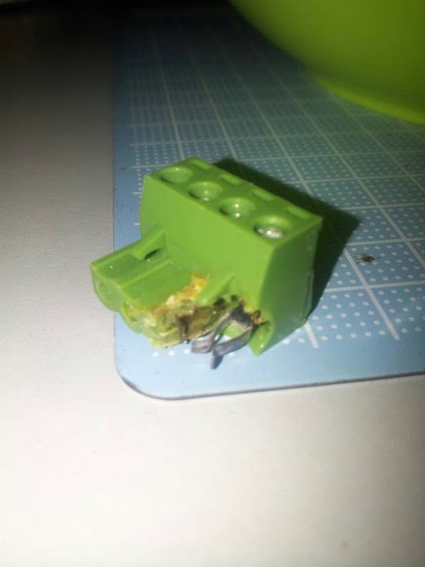
So, let's get back to the real underlying requirement. I don't think you've said what the actual current requirement of the bed is, you mention 15A and 20A but I'm not sure which is the real number. You say you run a 12V system, does the bed have a power rating? The MSTBA connector shown in your photo (or what's left of it) is only spec'd for 12A per way at best but it looks like there might be some load sharing going on which could potentially double that.
[Actually, that's a thought, if there is load sharing by design you did connect all four wires didn't you? If one of them was disconnected the current would all flow down one way which would then be well beyond it's capacity.]
The MSTBA pin is spec'd at 1mm with a recommended hole of 1.4mm so there should be 1.4mm to get wire into but as I said, personally I'd use a connector of some sort. Hey, here's a thought, why not use a MSTBA connector? After all it will fit :-) Alternatively Maplin sell these:
[www.maplin.co.uk]
which would fit the hole (I believe they are stackable to make a 4-way) and are rated at 24A so should be quite happy in an application where an MSTBA was previously deemed OK.
Good luck with the repair.
|
Re: terminal got burnt April 25, 2015 10:22PM |
Registered: 8 years ago Posts: 125 |
From looking at the pictures supplied in the OP, the terminals and board overheated but good.
To address issue #1: These removable connectors are subject to all sorts of issues at high current levels. The solder connections have to be exquisite and with the solders that are being used that are lead-free, making a good, solid connection is getting harder and harder to do. The connectors themselves have their own issues as well. When putting the wires into the removable part, the plug can't be attached to the board or the two contact fingers will get spread apart and cause grief. The wiring is stranded, more less than likely, and should not be tinned but left free for the strands to seat on connector tightening. For the high currents that heated beds can draw, for example a 12"x12" bed can draw 20 amps, these should be screw terminal barrier strip.
Issue #2: The truncated soldering pads that I saw on the board do not allow for a firm, solid filleted connection and can exacerbate thermal fatigue and cracking in the solder connections, leading to heating and eventual fail.
Issue #3: Current vs. wire gauge. 14 ga. stranded, in free air, is good for about 25 amps and 12 ga. is good for 30 amps. All connections have to be clean and tight to keep heating to as low as possible. Once a connection starts heating, it can run away and cause a catastrophe.
Summing up, when dealing with electrical equipment, all connections have to be checked over all of the time and installed right the first time for a long life.
|
Re: terminal got burnt April 26, 2015 06:06AM |
Registered: 9 years ago Posts: 476 |
I'm sorry for being late on posting the picture of the cable used, here it is
I guess I am quite lucky the heated bed suddenly turned off upon reaching 70'c. I just got some cables rated at 13a and 18a, unsure about the awg rating because we don't use awg here (Malaysia).


I guess I am quite lucky the heated bed suddenly turned off upon reaching 70'c. I just got some cables rated at 13a and 18a, unsure about the awg rating because we don't use awg here (Malaysia).
|
Re: terminal got burnt April 26, 2015 07:40AM |
Registered: 8 years ago Posts: 125 |
My apologies for not including mm3 for the wire. I deal with conversions between both professionally and just plain forgot. Here is a page that has a simple AWG/mm3/amps capacity chart - [www.wecoconnectors.com].
The rule of thumb is that any connection is a point of failure and thermal cycling aggravates that process because of expansion/contraction. I have replaced many a crimp connection and burnt wire because the crimp came loose, not properly compressed, or the wrong sized wire/crimp combination. Whenever I know that a crimp connection is going to be carrying high currents or subject to vibration, I always solder it after crimping. For me, that is an added insurance policy. One of the biggest issues with insulated crimps is transferring the compressive force from the crimp dies to the crimp itself through the insulation. The insulation can itself cause issues as well - moisture affects the material - as it does with our filament when printing. If the insulation soaks up moisture and you crimp it, it squeezes out and does not transfer the force correctly which results in an undercompressed crimp. Another issue is the crimp itself and the metal it is made from. I have had situations where I spent the funds for a batch of crimp connectors from what I thought to be a reputable manufacturer and they ended up to be substandard. So, in my book, it is a lottery and I don't like taking chances as the end result can be really expensive, especially in a production environment.
Because of this issue, I prefer to use uninsulated crimps. After crimping, I solder the connection and then use heat shrink tubing over the barrel part to insulate it. For this, I prefer white over black because I can use a black permanent marker and label what the wire is.
On to the subject of wire. I remember someone on a different thread talking about using teflon insulated wire for the heat bed wiring. My issue with teflon insulation is that it is fragile. Any rubbing against a sharp object, such as a corner, and it pierces very easily and to properly remove the insulation for connections, a thermal stripper has to be used to melt through it. I would suggest, instead of teflon, use a wire that uses a silicone insulation. As a suggestion, here is a wire distributor's webpage for UL 3239 / UL 10475 silicone wiring: [www.awcwire.com]. There is enough information on the page that can be taken and used to acquire the same from a different distributor. The insulation is thicker than regular wire, but it is quite flexible, heat tolerant (to 150 deg C / 300 deg F), and rugged. This would make for good use on the moving heat bed connection.
I think that I have covered enough for now. Have a good day.
|
Re: terminal got burnt April 26, 2015 08:03AM |
Registered: 9 years ago Posts: 476 |
Quote
itchytweed
My apologies for not including mm3 for the wire. I deal with conversions between both professionally and just plain forgot. Here is a page that has a simple AWG/mm3/amps capacity chart - [www.wecoconnectors.com].
The rule of thumb is that any connection is a point of failure and thermal cycling aggravates that process because of expansion/contraction. I have replaced many a crimp connection and burnt wire because the crimp came loose, not properly compressed, or the wrong sized wire/crimp combination. Whenever I know that a crimp connection is going to be carrying high currents or subject to vibration, I always solder it after crimping. For me, that is an added insurance policy. One of the biggest issues with insulated crimps is transferring the compressive force from the crimp dies to the crimp itself through the insulation. The insulation can itself cause issues as well - moisture affects the material - as it does with our filament when printing. If the insulation soaks up moisture and you crimp it, it squeezes out and does not transfer the force correctly which results in an undercompressed crimp. Another issue is the crimp itself and the metal it is made from. I have had situations where I spent the funds for a batch of crimp connectors from what I thought to be a reputable manufacturer and they ended up to be substandard. So, in my book, it is a lottery and I don't like taking chances as the end result can be really expensive, especially in a production environment.
Because of this issue, I prefer to use uninsulated crimps. After crimping, I solder the connection and then use heat shrink tubing over the barrel part to insulate it. For this, I prefer white over black because I can use a black permanent marker and label what the wire is.
On to the subject of wire. I remember someone on a different thread talking about using teflon insulated wire for the heat bed wiring. My issue with teflon insulation is that it is fragile. Any rubbing against a sharp object, such as a corner, and it pierces very easily and to properly remove the insulation for connections, a thermal stripper has to be used to melt through it. I would suggest, instead of teflon, use a wire that uses a silicone insulation. As a suggestion, here is a wire distributor's webpage for UL 3239 / UL 10475 silicone wiring: [www.awcwire.com]. There is enough information on the page that can be taken and used to acquire the same from a different distributor. The insulation is thicker than regular wire, but it is quite flexible, heat tolerant (to 150 deg C / 300 deg F), and rugged. This would make for good use on the moving heat bed connection.
I think that I have covered enough for now. Have a good day.
I am sorry, I still don't get much about the wire selections, would it be better to use a flex cable compared to a non-flex cable?
I also ordered another ramps shield just in case and browsing through a series of terminal blocks. Any recommendations which terminal blocks that is better? the one used for heated bed is blue, power supply is black, I wonder if they can be fitted to change the green terminal blocks in the power input for ramps?
|
Re: terminal got burnt April 26, 2015 10:01AM |
Registered: 8 years ago Posts: 125 |
I would use flexible wire. Stay away from solid core wire with removable terminal blocks. For a strain relief, put a loose loop in the wire before it goes into the terminal block. The loop will compensate for strain of the cable - its weight and movement.
With regards to terminal color, I would not use that as a gauge to current carrying capability. The connector blocks aren't coded that way and the only way is to look at the part number molded into the side of the connector. Color coding is used to group functions so plugs hopefully don't make their way into the wrong sockets during assembly and / or maintenance. From the part number, hopefully the current capacity of the connector can be found, unless you measure the diameter of the socket pin and treat that as a solid conductor. That though does not take into account the spring connections in the plug and they may be of a lower capability.
With regards to terminal color, I would not use that as a gauge to current carrying capability. The connector blocks aren't coded that way and the only way is to look at the part number molded into the side of the connector. Color coding is used to group functions so plugs hopefully don't make their way into the wrong sockets during assembly and / or maintenance. From the part number, hopefully the current capacity of the connector can be found, unless you measure the diameter of the socket pin and treat that as a solid conductor. That though does not take into account the spring connections in the plug and they may be of a lower capability.
|
Re: terminal got burnt April 26, 2015 10:44AM |
Registered: 9 years ago Posts: 476 |
What i meant was, will it be a good idea to change the stock connector to a higher capacity lets say stock is 15a, but i wanted to change to 30a, in a form of connector from power supply, black one with cover.
With that both ends of the wire would be crimped to a wishbone type terminal end
Will this helps in preventing the terminal getting burnt like what i encountered?
With that both ends of the wire would be crimped to a wishbone type terminal end
Will this helps in preventing the terminal getting burnt like what i encountered?
|
Re: terminal got burnt April 26, 2015 12:52PM |
Registered: 8 years ago Posts: 125 |
Changing the connector to a 30 amp unit will make it more rugged but now the limit becomes what the board construction / traces can handle. Too much current there and the traces will fuse open.
This can help as using the fork style connector with a screw terminal will help with the current carrying.
This can help as using the fork style connector with a screw terminal will help with the current carrying.
|
Re: terminal got burnt April 26, 2015 08:30PM |
Registered: 9 years ago Posts: 476 |
Quote
itchytweed
Changing the connector to a 30 amp unit will make it more rugged but now the limit becomes what the board construction / traces can handle. Too much current there and the traces will fuse open.
This can help as using the fork style connector with a screw terminal will help with the current carrying.
Wouldn't that be the same if I solder a higher capacity cables onto it?
|
Re: terminal got burnt April 27, 2015 09:02AM |
Registered: 8 years ago Posts: 125 |
One can solder the cables directly to the board but there can be no strain on the wire. If there is, that could lead to ripping the copper off of the board and maybe damaging it beyond repair.
Quote
sarf2k4
Quote
itchytweed
Changing the connector to a 30 amp unit will make it more rugged but now the limit becomes what the board construction / traces can handle. Too much current there and the traces will fuse open.
This can help as using the fork style connector with a screw terminal will help with the current carrying.
Wouldn't that be the same if I solder a higher capacity cables onto it?
|
Re: terminal got burnt April 27, 2015 09:15PM |
Registered: 9 years ago Posts: 476 |
|
Re: terminal got burnt April 28, 2015 11:56AM |
Registered: 8 years ago Posts: 125 |
Quote
sarf2k4
Let's say I'm running my bed at 110'c with 270'c extruder, how much amp would that be pulled?
I am using geeetech prusa i3 and the pid thingy should be default values, nothings changed
Can't answer question. No usable information. Need two out of the three pieces of info listed: voltage, amps, resistance. If I have volts and resistance, amps is a simple calculation.
|
Re: terminal got burnt April 28, 2015 02:01PM |
Registered: 9 years ago Posts: 30 |
Quote
itchytweed
Quote
sarf2k4
Let's say I'm running my bed at 110'c with 270'c extruder, how much amp would that be pulled?
I am using geeetech prusa i3 and the pid thingy should be default values, nothings changed
Can't answer question. No usable information. Need two out of the three pieces of info listed: voltage, amps, resistance. If I have volts and resistance, amps is a simple calculation.
To expand on that answer a little, the instantaneous current "the number of amps" is a function of the volts (V), amps (I), resistance (R). I=V/R.
But that doesn't tell you the whole story and in particular it's not that useful when considering the heating effect on the wire and connections of your printer. For that you need to know things which are tricky to find out, the thermal characteristics of the bed in particular. As your bed heats up from cold the bed will be powered 100% of the time, this is the worst situation for the wiring as it's carrying the full current all of the time. Once the bed gets to its target temperature the bed will be switched on and off to keep it there, the ratio of on to off will depend on how much heat is being lost from the bed (which is virtually unknowable). Because the bed is only being powered a proportion of the time the wiring doesn't get as hot.
In the case you mention, 110C bed, you'll be working your heater really hard and I guess it will be struggling to reach and then maintain that temperature so I'd expect it to run at nearly 100% ratio.
As I said earlier, current ratings for cable are a little odd, they're a bit of a shorthand, it's really a calculation involving how much temperature rise you can tolerate, how much voltage drop, and how long a cable run. What they are really saying is that assuming the cable performs exactly as specified and for a certain acceptable temperature rise the cable can take this much current. Notice, that's only the cable not the connections.
Back to your real-world problem. You did not have a problem with the cable, it worked fine. You had a problem with the MSTBA two-part connector. I can't see why a two part connector was used in that application anyway so I'd simply replace it with a suitable screw terminal and solve your problem that way. To do that I'd look for a terminal block which had the highest current rating I could find and still fitted in the holes.
|
Re: terminal got burnt April 28, 2015 08:52PM |
Registered: 9 years ago Posts: 476 |
Thank you for your reply, I probably going to have myself a terminal block just like the power output probably this weekend fitted on to the power input. As I understand right, this kind of terminal block has a high contact points especially paired with flexible multi strand wire right? A solid core weren't good to be used for these as well?
Correct me if I'm wrong
That is quite a hectic process when finding out the max current
Correct me if I'm wrong
That is quite a hectic process when finding out the max current
|
Re: terminal got burnt April 29, 2015 02:39AM |
Registered: 9 years ago Posts: 30 |
Quote
sarf2k4
Thank you for your reply, I probably going to have myself a terminal block just like the power output probably this weekend fitted on to the power input. As I understand right, this kind of terminal block has a high contact points especially paired with flexible multi strand wire right? A solid core weren't good to be used for these as well?
Correct me if I'm wrong
That is quite a hectic process when finding out the max current
I'd avoid solid core wire on a printer, go with multi-stranded flexible wire. Use the biggest which fits in the hole.
Make sure there's no strain on the wire, including sideways.
Make sure the connection is done up well.
Make sure the wires are properly striped and the copper clean where it sits in the terminal block.
|
Re: terminal got burnt April 29, 2015 05:11AM |
Registered: 9 years ago Posts: 476 |

|
Re: terminal got burnt May 02, 2015 10:28PM |
Registered: 9 years ago Posts: 476 |
Hi. I soldered a new terminal blocks on to the pcb, and did a test on heated bed only but not others because of the wires too short and the coppers didnt fully inserted into the terminal. Going to have a new slightly longer wire later.
However, last night i found out that theres some text saying "250v8a" while the other side is "22-14awg" and it got me worried. What if the terminal blocks that i just soldered is only 8amp if i refer to the first text but what about the rated awg at the other side?
With that the heated bed didnt have any issues heating up to 110c. Like i sidaid earlier, i didnt turn on the extruder. The terminal blocks still ok and no signs of melting.
I need guidance in my terminal blocks because the store where i bought these yesterday were literally dumb and dont know what is rhe capacity of the terminal blocks
Regards
Sarf
|
Re: terminal got burnt May 02, 2015 10:50PM |
Registered: 9 years ago Posts: 606 |
It's rated for a max of 250 volts and 8 amps, and will *physically* accept 22awg through 14awg wire.
The wire size rating has nothing to do with current rating - just the physical size of the terminals.
Generally, in higher current applications, I hate these damn things . . . I have some automated lighting gear that uses them, and they arethe biggest sore spot in the product, failing/burning/damaging boards way too often. If you want to remove plug on connector as a point of failure, replace with the same size screw terminal connector. You can't unplug it then, but how hard is it really to remove/replace two wires?
- Tim
|
Re: terminal got burnt May 02, 2015 11:06PM |
Registered: 9 years ago Posts: 476 |
|
Re: terminal got burnt May 03, 2015 12:36AM |
Registered: 9 years ago Posts: 606 |
I honestly don't understand what pins you are pushing on, but do know that if you have that tenuous a connection, more heating, burning, and board damage is in your very near future. Myself, I would upgrade to screw down strips (same style as the heater outputs) in the appropriate size, or at the very least, replace the entire connector pair - once a contact overheats that bad, it loses it's springiness and will never make good contact again.
Edited 1 time(s). Last edit at 05/03/2015 12:36AM by tadawson.
Edited 1 time(s). Last edit at 05/03/2015 12:36AM by tadawson.
|
Re: terminal got burnt May 03, 2015 05:23AM |
Registered: 9 years ago Posts: 30 |
Quote
tadawson
I honestly don't understand what pins you are pushing on, but do know that if you have that tenuous a connection, more heating, burning, and board damage is in your very near future. Myself, I would upgrade to screw down strips (same style as the heater outputs) in the appropriate size, or at the very least, replace the entire connector pair - once a contact overheats that bad, it loses it's springiness and will never make good contact again.
I'm with tadawson on this, I can't see any advantage of a plug-in connector but there is the big disadvantage that it is a likely point of failure. A solid, screw-down terminal gives you the assurance that it's inspectable and secure. The Maplin ones I linked to further up the thread are the sort of thing I mean.
And remember, you need to make sure all four wires are connected properly. The bed will heat up with one of the four disconnected or high resistance but overheating and failure of it's sister wire's connection will inevitably result.
Your comments about what you've done are a little odd, particularly "the coppers didnt fully inserted into the terminal". I'm not sure what you mean exactly but anyway whatever, it needs fixing before you move on. Again, I'd simply pick the fattest flexible wire which physically fits into the terminal hole. Within any limits you care about (and this is only true at the low voltages you're working at - it's not the case with mains for instance) all wires will have the same current capacity as it's a function of the amount of copper, ie. the cross-sectional area.
|
Re: terminal got burnt May 03, 2015 05:34AM |
Registered: 9 years ago Posts: 476 |
I bought this style of terminal blocks because there are metal will clamp the wire inside, I used a flat head screw to push it up again so i can take out the wire easily.
Should I change the terminal block to a 16a type?
Should I change the terminal block to a 16a type?

Sorry, only registered users may post in this forum.