Vertical vs Horizontal X rods arrangement? What distance between rods?
Posted by realthor
|
Vertical vs Horizontal X rods arrangement? What distance between rods? April 09, 2016 01:43PM |
Registered: 9 years ago Posts: 1,035 |
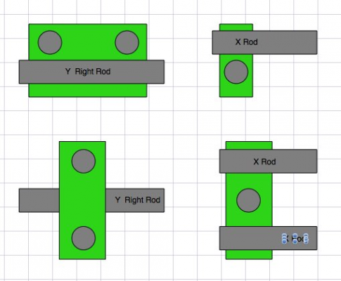
Hi, is there one solution better than the other? I have entered the CoreXY arena with vertically stacked X axis in mind - rods just as Prusas and then Smartrapcore have them. But over time I kept questioning it. Horizontally spaced rods don't actually eat up more space than the vertically stacked rods, as I originally believed. And the design of the carriage can be quite simpler for the horizontal variation. Also the X carriage seems to be easier to design, print and even rep-strap.
I really need your opinions on this and maybe an explanation on why one is superior to the other. And what is a minimum recommended distance between rods (I know wider gap is better for stability ... maybe a variable distance design?).
Thanks.
Edited 1 time(s). Last edit at 04/09/2016 01:44PM by realthor.
RepRap Lander concept on Concept Forge
RepRap Lander concept on RepRap Forums
My Things, mostly experimental stuff
|
Re: Vertical vs Horizontal X rods arrangement? What distance between rods? April 09, 2016 01:56PM |
Registered: 11 years ago Posts: 5,780 |
With vertically spaced rails, when the extruder carriage is at the center of the axis there will usually be a little twist because the extruder carriage tends to be hanging off one side of the rails. With horizontally spaced rails, the extruder mass may be more evenly split between the rails and so while there may be some sag, there probably won't be much twist. Either way works as long as the sag and twist aren't excessive, primarily a function of the extruder carriage mass and length of the rails.
Ultra MegaMax Dominator 3D printer: [drmrehorst.blogspot.com]
Ultra MegaMax Dominator 3D printer: [drmrehorst.blogspot.com]
|
Re: Vertical vs Horizontal X rods arrangement? What distance between rods? April 09, 2016 01:58PM |
Registered: 9 years ago Posts: 1,035 |
What about a minimum/recommended distance between rods? There are usually two linear bearings on each Y axis so I guess the same distance between rods ensures the greatest stability...
Example: for a LM10UU, each bearing's length is about 29mm so 29x2=58mm so for 8mm rods for X it would mean that the maximum distance between them would be 58-4-4=50mm, which I presume is very ok as a distance.
Oh, and guys, I know this boils down to preference, but what are the most successful X carriages you have had/designed. I'd like to learn from both sides, vertical and horizontal. I have designed a vertical one so I have spent quite some time with that arrangement. But for the horizontal variation I am only reading about right now. I see RichRap's Quick-fit carriage in the top on thingiverse although it's designed in 2012.
Edited 2 time(s). Last edit at 04/09/2016 02:34PM by realthor.
RepRap Lander concept on Concept Forge
RepRap Lander concept on RepRap Forums
My Things, mostly experimental stuff
|
Re: Vertical vs Horizontal X rods arrangement? What distance between rods? April 09, 2016 03:49PM |
Registered: 9 years ago Posts: 1,035 |
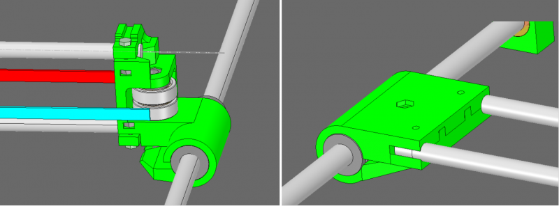
I might have found a "weakness" of the horizontal-style arrangement. It seems to me that in a vertical stacking the length of rod that needs to be lost inside the Y carriage can be less than in the horizontal arrangement. As the weight of the printhead tries to collapse the X plane, in a vertical stacking the upper rod acts like a stopper of this virtual collapse while in the horizontal arrangement it doesn't. Frankly I hope it is just late and I am tired and this isn't so
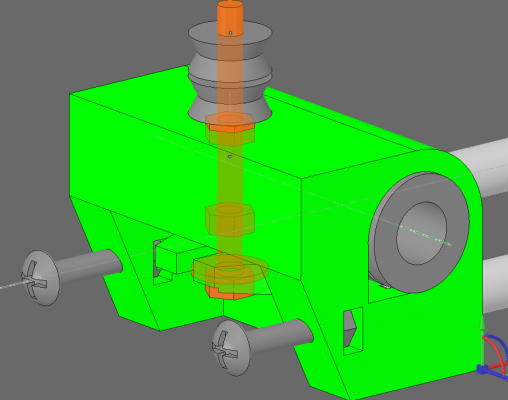
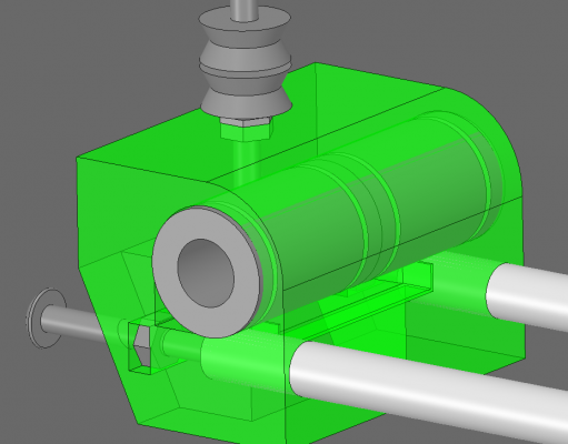
This is an example from my current WIP designs, I didn't have much else at hand to exemplify. But it looks like the image on the right would be so much easier to collapse should force be applied in the middle. Maybe a much thicker meat around the rods would be appropriate.
Edited 1 time(s). Last edit at 04/09/2016 03:50PM by realthor.
RepRap Lander concept on Concept Forge
RepRap Lander concept on RepRap Forums
My Things, mostly experimental stuff
|
Re: Vertical vs Horizontal X rods arrangement? What distance between rods? April 09, 2016 06:50PM |
Registered: 11 years ago Posts: 5,780 |
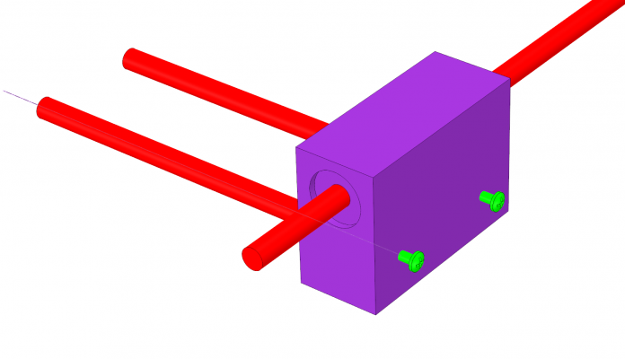
In your design you're using the X axis guide rails as the structural backbone of the X axis. That means you need to cut the rails to exact lengths and then make sure that the bearing blocks at the Y axis come right up to the ends of the X axis rails. If there's any space between the end of the rail and the bearing block, the X axis belt tension is going to pull the bearing blocks closer together and flex the Y axis rails inward.
I think it would be better to have a couple screws in one of the Y axis bearing blocks that would allow you to "close the gap" between the ends of the guide rails and the bearing block so you could ensure that the spacing is constant and correct regardless of X axis belt tension. You wouldn't have to cut the rails to accurate lengths and you wouldn't have to make the bearing blocks so precise, at least in that dimension.
Ultra MegaMax Dominator 3D printer: [drmrehorst.blogspot.com]
|
Re: Vertical vs Horizontal X rods arrangement? What distance between rods? April 09, 2016 07:14PM |
Registered: 11 years ago Posts: 1,049 |
That is because of your green plastic mount.
Why are you designing for the plastic to take the load
in a way that it is cracking in half
Use the plastic in compression or tension
Do these LU bearings use circulating balls or just a line of balls?
Better yet ditch these rods and LULUs
Use real guide rails SGRs (round rod) or MGNs (dovetail)
For a guy that wants all this precision you sure like the cheep crap

|
Re: Vertical vs Horizontal X rods arrangement? What distance between rods? April 09, 2016 07:23PM |
Registered: 9 years ago Posts: 1,035 |
@d_d: Thanks for the input, i've never thought of that. My X rods are cut to length (340mm) by the vendor but then the Y carriages have to be pretty exact as you say. I was trying by this design to have the X rods and Y rods on as close as possible planes. But the back screws suggestion is a good one and I actually remember seeing it on the solidoodle Y carriages if I am not mistaken.
@Cozmicray: I already have the rods so i'd better use them for now.
Edited 2 time(s). Last edit at 04/09/2016 07:56PM by realthor.
RepRap Lander concept on Concept Forge
RepRap Lander concept on RepRap Forums
My Things, mostly experimental stuff
@Cozmicray: I already have the rods so i'd better use them for now.
Edited 2 time(s). Last edit at 04/09/2016 07:56PM by realthor.
RepRap Lander concept on Concept Forge
RepRap Lander concept on RepRap Forums
My Things, mostly experimental stuff
|
Re: Vertical vs Horizontal X rods arrangement? What distance between rods? April 10, 2016 03:25PM |
Registered: 9 years ago Posts: 1,035 |
Ok, I listened and got to an arrangement that I kind of like. I know this is diverting from the thread itself but I felt obliged to follow-up.
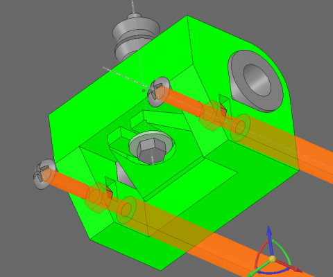
I got the screw-backed rods like @the_digital_dentist suggested and the plastic part is now in tension as @cozmicray suggested. But, compared to the vertical stack in my previous post, this design just takes more space and the footprint of the frame is somewhat larger than what is needed for that particular design (the downside is that the vertical stacked rods design suffers from what @the_digital_dentist warned, having no "stop" for the rods).
So here it is:
The linear bearings are clamped firmly by the central bolt that acts also as the spindle for the radial bearings above. The rods will be forcefully driven into the plastic part in this particular design as the Y carriages are quite tiny. BTW, I've taken a look around and you can't imagine how hard it is to find a design complying with the advises you guys have given me here.
Edited 2 time(s). Last edit at 04/11/2016 07:33PM by realthor.
RepRap Lander concept on Concept Forge
RepRap Lander concept on RepRap Forums
My Things, mostly experimental stuff
|
Re: Vertical vs Horizontal X rods arrangement? What distance between rods? May 18, 2016 02:25PM |
Registered: 8 years ago Posts: 776 |
ok so just as a cross-reference, i tried vertical rods (as opposed to and specifically distinct from vertical linear rails, as well as specifically distinct from horizontal rods): they're an unmitigated disaster. details here: [forums.reprap.org]
Edited 1 time(s). Last edit at 05/18/2016 02:26PM by lkcl.
Edited 1 time(s). Last edit at 05/18/2016 02:26PM by lkcl.
Sorry, only registered users may post in this forum.
