Printer design: ParalaXXY
Posted by ParalaX
|
Printer design: ParalaXXY May 01, 2020 10:41AM |
Registered: 7 years ago Posts: 6 |
Hi everyone!
About 3 years ago I started into 3D printing with a P3Steel Toolson MK2. I still use it as of today, and recently, I printed a few of stuff for the COVID-19 medical teams. While my printer can produce quiet nice result, it is a bit small, and a bit slow, so I figured I'd make a new one
After much reading, I decided to go with the coreXY style, and took a good reading at this great blog: [drmrehorst.blogspot.com].
I see that the author is on the forum, so if you come in this topic, thanks a lot for putting all this information out!
So, about the project. First of all, the goals I'd like to achieve:
- Bed of around 400mmx400mm, with 500mm linear rails for motion
- Smallest footprint possible
- Dual extrusion, with a chimera and Bowden setup
- Head as light as possible in order to be able to crank up the speed.
- I'd like to have a cost less than 700€ if possible, and no more then 1000€ in all cases
The main point of the construction will be:
- 3mm aluminimum laser cut frame (or steel if needed)
- 500mm linear rails
- As much metal as possible for the moving part
- I think (but I'm not entirely sure about that) about a 3 point fixation for the Z axis, with one motor and a belt
At the moment, I just started the design, with the XY carriage and motor mount. Here is an overview:
I'll use bearings staks on top of each other, but I'll use 624ZZ instead of 608ZZ as they are smaller, but the same radius than the GT2 20 tooth belt pulley, so I should be fine regarding the bending radius:
The alignment is calculated so that the important segment are parallels.
I can only put a 6mm belt, but maybe I'll make a washer between the ball bearings, or add a third, thin one, to get the 9mm.
I haven't included the screws yet, but the bearings will be held in place with a M4x30 screw, and I will use 4 screws that goes from the top to the rails to fix everything in place
I know it is early work, but do you already see some mistakes in my construction? Any suggestions?
Regards,
ParalaX
Edited 1 time(s). Last edit at 05/01/2020 10:43AM by ParalaX.
About 3 years ago I started into 3D printing with a P3Steel Toolson MK2. I still use it as of today, and recently, I printed a few of stuff for the COVID-19 medical teams. While my printer can produce quiet nice result, it is a bit small, and a bit slow, so I figured I'd make a new one
After much reading, I decided to go with the coreXY style, and took a good reading at this great blog: [drmrehorst.blogspot.com].
I see that the author is on the forum, so if you come in this topic, thanks a lot for putting all this information out!
So, about the project. First of all, the goals I'd like to achieve:
- Bed of around 400mmx400mm, with 500mm linear rails for motion
- Smallest footprint possible
- Dual extrusion, with a chimera and Bowden setup
- Head as light as possible in order to be able to crank up the speed.
- I'd like to have a cost less than 700€ if possible, and no more then 1000€ in all cases
The main point of the construction will be:
- 3mm aluminimum laser cut frame (or steel if needed)
- 500mm linear rails
- As much metal as possible for the moving part
- I think (but I'm not entirely sure about that) about a 3 point fixation for the Z axis, with one motor and a belt
At the moment, I just started the design, with the XY carriage and motor mount. Here is an overview:

I'll use bearings staks on top of each other, but I'll use 624ZZ instead of 608ZZ as they are smaller, but the same radius than the GT2 20 tooth belt pulley, so I should be fine regarding the bending radius:

The alignment is calculated so that the important segment are parallels.
I can only put a 6mm belt, but maybe I'll make a washer between the ball bearings, or add a third, thin one, to get the 9mm.
I haven't included the screws yet, but the bearings will be held in place with a M4x30 screw, and I will use 4 screws that goes from the top to the rails to fix everything in place

I know it is early work, but do you already see some mistakes in my construction? Any suggestions?
Regards,
ParalaX
Edited 1 time(s). Last edit at 05/01/2020 10:43AM by ParalaX.
|
Re: Printer design: ParalaXXY May 01, 2020 12:35PM |
Registered: 11 years ago Posts: 5,780 |
What sort of frame will that be mounted on? The thin plate isn't going to be very rigid. That 3 mm sheet probably won't be very flat, which means your Y axis guides may not be sitting in the same plane. I used 1/4" (6.35 mm) cast tooling plate because it is milled flat on both surfaces, and wouldn't flex much. That was bolted to 4040 t-slot to ensure rigidity.
Will you be heating the enclosure? If so, don't skip the second bearing block for the X axis. When the printer's frame heats up it will expand and the Y axis guide rails will move apart. Linear guides are very intolerant of that sort of thing. Your X axis rail may be a bit too flexible to use without some support like a metal tube to help stiffen it.
If you're not planning to heat the enclosure (or not planning to enclose at all) I suggest you reconsider. You won't be able to print much ABS on an open printer, so you'll end up printing a lot of PLA. The problem with PLA is that it can't take any heat at all. Leave it in a hot car and it will melt. It's good for printing stuff you are going to throw away, but not for stuff you expect to keep around for a long time. It would be a shame to spend so much building a good printer and be unable to print ABS. Mount the electronics outside of the enclosure to maximize operating life.
Regarding speed... there's a limit to how fast you can melt filament and squirt it out of a nozzle. Extrusion is the limiting factor in FDM printing, not moving the mechanism. A Bowden setup will keep moving mass down a bit, but will also prevent printing flexible filament like TPU. Try some TPU if your current printer has a direct extruder- it's extremely tough, flexible stuff with many uses.
Ultra MegaMax Dominator 3D printer: [drmrehorst.blogspot.com]
|
Re: Printer design: ParalaXXY May 01, 2020 02:44PM |
Registered: 7 years ago Posts: 6 |
Hello!
Thanks a lot for your feedback!
I will make the frame myself, also from aluminium sheets, so I can add reinforcement where needed. But I haven't got to this part yet...
I didn't think 3mm wouldn't be enough... I will use this site to do the laser cutting: [www.john-steel.com]. So there is plenty of material to choose from, and aluminium 6mm is in the list So I'll take that. Or do you think it would be best to use steel for the plate, and aluminium for the rest?
I know ABS Is very nice, but unluckily it's also toxic, so I won't be using it unless I can make a full enclosure with HEPA filter, so I'd like to prepare everything needed to enclose the printer, and do the update later. I'll see how I can stiffen the X axis. For the X, sorry but I don't understand what you mean about the second bearing block?
About the flexible printing, my initial idea was to use a chimera "head", with Bowden extruder, but be able to easily swap (just the 4 screws of the rail) for a direct drive extruder. I don't mind spending 30min to change tools between prints as I won't be using a lot of flexible filament. If in the future that happen to change, I can also create a hybrid extruder with one Bowden and one direct drive for instance
Thanks a lot for your remarks! I'll implement that for sure and come back when the project moves on.
Thanks a lot for your feedback!
I will make the frame myself, also from aluminium sheets, so I can add reinforcement where needed. But I haven't got to this part yet...
I didn't think 3mm wouldn't be enough... I will use this site to do the laser cutting: [www.john-steel.com]. So there is plenty of material to choose from, and aluminium 6mm is in the list
So I'll take that. Or do you think it would be best to use steel for the plate, and aluminium for the rest?I know ABS Is very nice, but unluckily it's also toxic, so I won't be using it unless I can make a full enclosure with HEPA filter, so I'd like to prepare everything needed to enclose the printer, and do the update later. I'll see how I can stiffen the X axis. For the X, sorry but I don't understand what you mean about the second bearing block?
About the flexible printing, my initial idea was to use a chimera "head", with Bowden extruder, but be able to easily swap (just the 4 screws of the rail) for a direct drive extruder. I don't mind spending 30min to change tools between prints as I won't be using a lot of flexible filament. If in the future that happen to change, I can also create a hybrid extruder with one Bowden and one direct drive for instance
Thanks a lot for your remarks! I'll implement that for sure and come back when the project moves on.
|
Re: Printer design: ParalaXXY May 01, 2020 05:03PM |
Registered: 11 years ago Posts: 5,780 |
This is a picture of the back side of the X axis in my printer.
Notice that there are two bearing blocks (green) on the X axis guide rail- one on the extruder carriage and one at the right end of the guide rail. On the left end of the guide rail there is a spacer (orange) that is the same thickness as the bearing blocks. The second bearing block on the far right is there to allow the Y axis rails to move apart when the printer's frame heats up. The X axis guide rail is firmly anchored to the left side Y axis rail via the spacer and the pulley mount. The guide rail is free to slide in the right side bearing block, but only in the X direction. When the Y axis rails move apart as the frame heats up, the X axis rail moves a little in that bearing block.
It's a small complication, but the extra X axis bearing block prevents the Y axis from binding when the temperature of the printer changes. I have seen posts from people who set up corexy mechanisms with linear guides in the summer and when their shop drops 20 degrees in the winter the mechanism won't move until they loosen up one of the Y axis rails and resecure it. It doesn't take much temperature change to move beyond the 20 um or so that the guide rails will tolerate.
UMMD has never had any issues with the mechanism binding, hot or cold.
Ultra MegaMax Dominator 3D printer: [drmrehorst.blogspot.com]
|
Re: Printer design: ParalaXXY May 02, 2020 07:36AM |
Registered: 4 years ago Posts: 5 |
Mounting your X rail on some kind of support plate, that is made from the same material (aluminium ?) as the rest of the frame, could also solve the issue. The support plate would then connect the two Y blocks. That way everything expands/retracts at the same rate (except for the rails - in case the frame is alu).
|
Re: Printer design: ParalaXXY May 02, 2020 01:45PM |
Registered: 7 years ago Posts: 6 |
|
Re: Printer design: ParalaXXY May 24, 2020 04:30PM |
Registered: 9 years ago Posts: 294 |
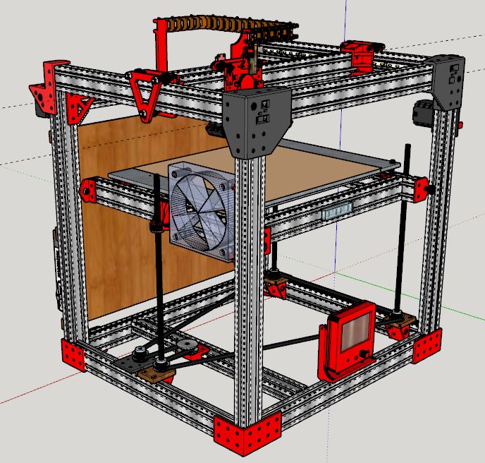
here is what I build based on Carl Feniak design on open build. Mine is 300x300x300 and is 2 inches smaller than Carl's plan.
I modeled it in Sketchup so I could insure things fit as I shrunk it. Dimensions approx 21x21x22 inches.
The thing I fell in love with is the way the belts run in the grooves of the v rails and do not cross over one another as in a typical CoreXY.
It has a piezo probe/endstop with a std dev of 0.002mm. The bed is supported on the 3 screws and only guided in the corners.
It has a MIC6 plate and 200W AC heater.
To expand it, just make the rails and screws longer.
More details if you want.
Sorry, only registered users may post in this forum.