Atfer Hbot, go to CoreXY.
Posted by zelogik
|
Re: Atfer Hbot, go to CoreXY. April 18, 2014 04:04AM |
Registered: 12 years ago Posts: 199 |
@A2:
The part holding the LM12UU bearings are actually two parts separated vertically at the center of the bearing. The screws you see in the image are used to connect the parts together. I designed it for 6 screws Two at the top (which you see in the image) two at the bottom and two in the middle. I only used 4, which seems enough.
Upto 4 screws are used to connect the part to the extrusion. Only one part is screwed to the extrusion. This way You can tighten the part securely to the extrusion without worrying about overtightening or uneven pressure on the bearings.
When designing I kept rigidity in mind, not the amount of screws or plastic. But I redesigned the outer part to this:
Hope this clears up some things.
You can find the complete design in my github
The part holding the LM12UU bearings are actually two parts separated vertically at the center of the bearing. The screws you see in the image are used to connect the parts together. I designed it for 6 screws Two at the top (which you see in the image) two at the bottom and two in the middle. I only used 4, which seems enough.

Upto 4 screws are used to connect the part to the extrusion. Only one part is screwed to the extrusion. This way You can tighten the part securely to the extrusion without worrying about overtightening or uneven pressure on the bearings.
When designing I kept rigidity in mind, not the amount of screws or plastic. But I redesigned the outer part to this:

Hope this clears up some things.
You can find the complete design in my github
|
Re: Atfer Hbot, go to CoreXY. April 18, 2014 04:33AM |
Registered: 10 years ago Posts: 1,381 |
@jand:
I'm sorry I wasn't more clear, I'm interested in how the aluminum extrusion brackets are retained.
Is this how they are typically assembled.
Got a link to the mfg.
Tks.
Edited 1 time(s). Last edit at 04/18/2014 04:33AM by A2.
I'm sorry I wasn't more clear, I'm interested in how the aluminum extrusion brackets are retained.
Is this how they are typically assembled.
Got a link to the mfg.
Tks.

Edited 1 time(s). Last edit at 04/18/2014 04:33AM by A2.
|
Re: Atfer Hbot, go to CoreXY. April 18, 2014 04:37AM |
Registered: 12 years ago Posts: 199 |
|
Re: Atfer Hbot, go to CoreXY. April 18, 2014 05:15AM |
Registered: 11 years ago Posts: 225 |
It's more a thing like that:
So you have plenty space on the other side (near X and Y motor).
The only difficulty is to not touch the XY carriage mouvement.

So you have plenty space on the other side (near X and Y motor).
The only difficulty is to not touch the XY carriage mouvement.
|
Re: Atfer Hbot, go to CoreXY. April 18, 2014 09:45AM |
Registered: 12 years ago Posts: 199 |
I am not sure I like this idea. This way you move the Z-axis to the front of the machine. Not a good idea. You can turn the machine 90 degrees and use one of the sides as the front, but i do not like that. I don't like the looks of the X-assembly moving left-right instead of front-back, like it is now.
I assume you want to place the Z-axis smooth rods at the black dots in the image. This is where the belts are crossing, so I would need another extrusion below the belts. I could shift up the one already there near the bottom.
I think it is possible, but not sure it is worth the trouble. My first priority is getting the machine printing. (Make a 1.0 release)
Besides I am very happy with the Z-axis like it is at the moment. It is running smooth and feels quite stable.
What do all of you think?
|
Re: Atfer Hbot, go to CoreXY. April 18, 2014 12:01PM |
Registered: 11 years ago Posts: 225 |
I'm an idiot ... of course the black dots are where the both belts crossing .... now that I have an enclosure I don't have seen it.
Now the only things I thinking for the others one is, there is enought space for put a E3D or Jhead or Prusa nozzle on the middle of the carriage. 18mm is large enought ... I don't have this problem because I have a custom nozzle.
For your printer, she seem beautiful and strong. I only see (maybe an optical illusion on your picture) that the Z motor is not centered between the two 12mm rods ...
Have you made some dry test with wade extruder on the carriage?
|
Re: Atfer Hbot, go to CoreXY. April 18, 2014 12:24PM |
Registered: 11 years ago Posts: 250 |
I've tried to simplify the design by using less nuts and bolts.
(Everything is still in the design phase and my CAD skills are lacking!)
Will be using zip ties instead of bolts to hold the linear bearings into place.
The roller bearings will be bolted into place
The Y axis use 12mm rods, and the X axis uses 8mm.
I'm reworking the belt retainer on the carriage. (Currently a tapered slot that tightens up on a folded belt)
(got a new nozzle and still playing with my settings so print quality isn't the greatest yet)
--------------------------------------------------------
Custom all metal CoreXY
- Duet 2 Wifi w/ PanelDue 7i
- 330mm x 360mm x 500mm
- 750w Silicon heater
Custom Mendel90
(Backup printer - Old reliable!) - Sold
(Everything is still in the design phase and my CAD skills are lacking!)
Will be using zip ties instead of bolts to hold the linear bearings into place.
The roller bearings will be bolted into place
The Y axis use 12mm rods, and the X axis uses 8mm.
I'm reworking the belt retainer on the carriage. (Currently a tapered slot that tightens up on a folded belt)
(got a new nozzle and still playing with my settings so print quality isn't the greatest yet)


--------------------------------------------------------
Custom all metal CoreXY
- Duet 2 Wifi w/ PanelDue 7i
- 330mm x 360mm x 500mm
- 750w Silicon heater
Custom Mendel90
(Backup printer - Old reliable!) - Sold
|
Re: Atfer Hbot, go to CoreXY. April 18, 2014 12:32PM |
Registered: 12 years ago Posts: 199 |
@zelogik:
Thanks for being an idiot, This meens I do not need to spend time on (thinking on) moving the Z-axis.
So I keep it like it is. If someone wants the motor at the bottom it is possible to do so without redesign.
I have an E3D hotend. It will fit, but it will be lower than on a mendel, because the ribs and fan do not fit inside the carriage. Still thinking how to solve it.
Yes you are correct the leadscrew WAS out of center.
Yes I did some dry run tests and it seems OK.
|
Re: Atfer Hbot, go to CoreXY. April 19, 2014 03:37AM |
Registered: 11 years ago Posts: 225 |
@Moga: Nice design, but ... I have just a little doubt on your design with the part who take LM12UU and bearing.
I will try to explain. When you will pull/tight your belt that part will "open".
I don't know if this design don't work at all, I just have a doubt ;-) You need to try. Normally the 8mm rod are there for that reason too. And normally ALL the tension are in the rod axis, no there is no problems of moments.
The XY carriage is really nice for single nozzle.
@Jand: Your welcome
I'm really excited to see that two printer in action, even if they have only the same belt path as my origin design Both have made amazing things.
I will try to explain. When you will pull/tight your belt that part will "open".
I don't know if this design don't work at all, I just have a doubt ;-) You need to try. Normally the 8mm rod are there for that reason too. And normally ALL the tension are in the rod axis, no there is no problems of moments.

The XY carriage is really nice for single nozzle.
@Jand: Your welcome
I'm really excited to see that two printer in action, even if they have only the same belt path as my origin design
Both have made amazing things.|
Re: Atfer Hbot, go to CoreXY. April 20, 2014 07:17AM |
Registered: 11 years ago Posts: 250 |
Thank you zelogik. 
I have the parts printed so I will try them, and see what happens.
I will make them stronger if they flex too much.
--------------------------------------------------------
Custom all metal CoreXY
- Duet 2 Wifi w/ PanelDue 7i
- 330mm x 360mm x 500mm
- 750w Silicon heater
Custom Mendel90
(Backup printer - Old reliable!) - Sold
|
Re: Atfer Hbot, go to CoreXY. May 07, 2014 05:28PM |
Registered: 12 years ago Posts: 199 |
My RepRap-XY has made a promotion. It has left my workbench and is allowed on my desk next to my mendel.
Jus a few images while printing the a set of belt-clamps:
I printed Nopheads famous cal.stl as one of the test objects. The results are good. The nuts are tight in the holes. I pressed them in with just my fingers. The vertical nuts on the side of the object fall out when you shake it just a little bit. Outside sizes are correct within 0.1 mm. I am happy with the results.
Another testobject was a squirrel. I am also happy with this object. You can see some horizontal banding. This is probably because I used a M8 threaded rod. So I consider replacing it with a TR10 leadscrew.
Here is a video of it printing: [youtu.be]
And finally a picture of the parent of this reprap:

Jus a few images while printing the a set of belt-clamps:


I printed Nopheads famous cal.stl as one of the test objects. The results are good. The nuts are tight in the holes. I pressed them in with just my fingers. The vertical nuts on the side of the object fall out when you shake it just a little bit. Outside sizes are correct within 0.1 mm. I am happy with the results.


Another testobject was a squirrel. I am also happy with this object. You can see some horizontal banding. This is probably because I used a M8 threaded rod. So I consider replacing it with a TR10 leadscrew.


Here is a video of it printing: [youtu.be]
And finally a picture of the parent of this reprap:

|
Re: Atfer Hbot, go to CoreXY. May 07, 2014 07:16PM |
Registered: 10 years ago Posts: 71 |
- CONGRATULATIONS -
...and let's put a pic of zelogik next to that mendel
Thanks for the vid ... now let it run at 150 mm/s and show us!
Could you give some data as to the extruder/hotend you are using now
Do your stepsticks work without any Heatsink and without fan ???
again: CONGRATULATIONS !!!
...and let's put a pic of zelogik next to that mendel
Thanks for the vid ... now let it run at 150 mm/s
and show us!Could you give some data as to the extruder/hotend you are using now
Do your stepsticks work without any Heatsink and without fan ???
again:
CONGRATULATIONS !!!
|
Re: Atfer Hbot, go to CoreXY. May 07, 2014 08:37PM |
Registered: 12 years ago Posts: 809 |
Really, really nice. Beautiful first prints. Can't wait to see more.
I am happy to say I am moving in this direction as well, but fewer printed parts and more milled aluminum.
- akhlut
Just remember - Iterate, Iterate, Iterate!
[myhomelessmind.blogspot.com]
Beautiful first prints. Can't wait to see more.I am happy to say I am moving in this direction as well, but fewer printed parts and more milled aluminum.
- akhlut
Just remember - Iterate, Iterate, Iterate!
[myhomelessmind.blogspot.com]
|
Re: Atfer Hbot, go to CoreXY. May 08, 2014 01:04AM |
Registered: 11 years ago Posts: 290 |
|
Re: Atfer Hbot, go to CoreXY. May 08, 2014 02:36AM |
Registered: 12 years ago Posts: 199 |
@reinhold:
Speed is not my first priority. My first priority is a stable, solid, rigid, reliable, etc. printer. But I will give it a try and share the results soon. I will give some more details on the extruder/hotend later today/tomorrow.
Yes the motor drivers are working fine without extra cooling. I can touch them without burning my fingers. Will add heatsinks later anyway.
@akhlut:
actually these are not the first prints, more like number 5 and 6. First print was with taulman 618 without the heated bed. If I can find it I will make a picture of the real first print.
@zingmann:
I guess it is OK to start printing, but wait unlit I updated my github. I will do that tonight.
The mendel is a Sells mendel or original mendel. the X-ends are from the durbie printer by romscraj. see [github.com]
This is where I got the idea for the Z-axis nut holder.
Edited 1 time(s). Last edit at 05/08/2014 11:07AM by jand.
|
Re: Atfer Hbot, go to CoreXY. May 08, 2014 02:39PM |
Registered: 12 years ago Posts: 199 |
Just a quick update.
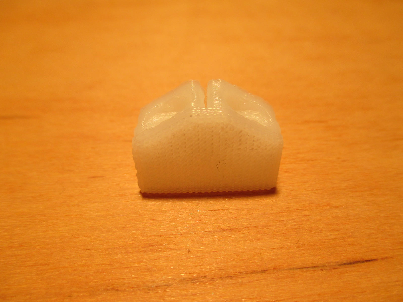
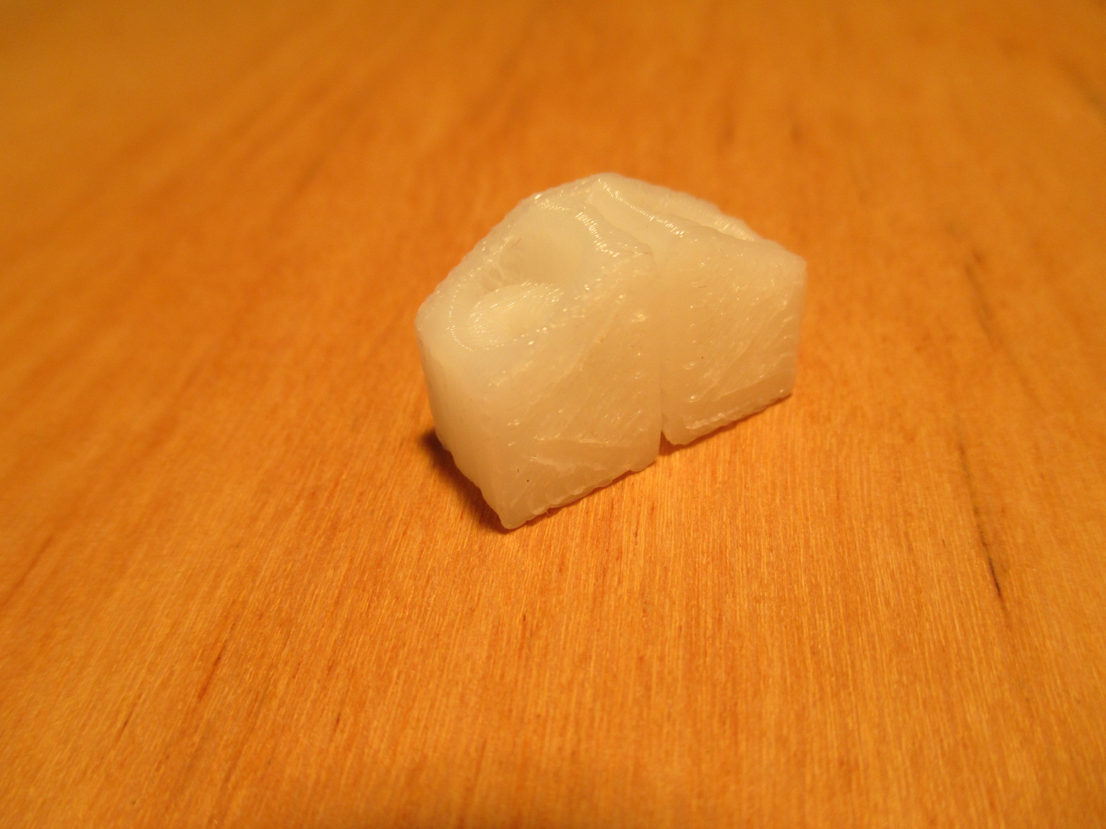
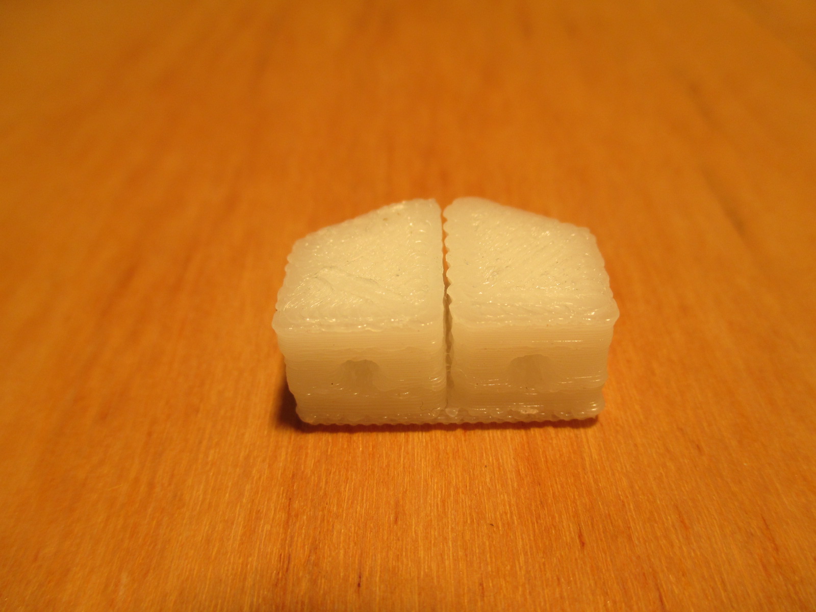
I found the actual first object I printed on this printer. It is a belt-clamp to connect the belt to the carriage.
I printed it in taulman 618, because at that time I did not have the resistors mounted on the heated bed. And I desperately wanted to print something.
As you can hopefully see in the bad quality pictures It has way to much plastic.
Not to bad for a first print. Way better than my first on the mendel, which was more like a plate of spagetty than a cube.
For those who want to start printing I updated the github. I think it is pretty much complete now. The only thing missing are the X and Y endstops. The adjustable Z endstop is in there
|
Re: Atfer Hbot, go to CoreXY. May 08, 2014 03:06PM |
Registered: 12 years ago Posts: 809 |
Even for a first print that's not bad at all. I posted your video to the Ingentis Builders Community on Google+ so others can see your hard work!
- akhlut
Just remember - Iterate, Iterate, Iterate!
[myhomelessmind.blogspot.com]
- akhlut
Just remember - Iterate, Iterate, Iterate!
[myhomelessmind.blogspot.com]
|
Re: Atfer Hbot, go to CoreXY. May 08, 2014 05:55PM |
Registered: 12 years ago Posts: 199 |
|
Re: Atfer Hbot, go to CoreXY. May 10, 2014 10:26AM |
Registered: 10 years ago Posts: 71 |
Hi Jan
Would you mind explaining/confirming some details of your heated table?
(it seems reality is "at least in part" unlike drawing )
0) Table size x mm x y mm (220x220) ?
1) (Borosilicate ?) Glass plate thickness h1 (3 mm) ?
2) Aluminium plate thickness h2 mm (6 mm)?
3) What sort of heater are you using? (4 different cable types confuse me ;-) )
4) The gap between Extrusion and upper Aluminum plate is because...?
5) "?" you have 3 (4?) springs with M5 screws to adjust table height?
6) Any special insulation used ?
7) Aluminium plate thickness h3 mm (6 mm)?
8) Do you print on the naked Glass plate
9) at which temperature (with PLA, Nylon, ABS) ?
10) ... how is the plate fixed to the extrusions... ;-)
(lot's of screws through the top aluminum plate...but)
How do you adjust the table height for a print anyway?
BOM: (^_*)
2 x Aluminum plate 220x220x 6mm
1 x Borosilicate plate 220x220x 3mm
Heater...
Temp Sensor...
Insulation ...
Springs...
screws M5 ...M4
P.S.:
The layer height for the squirrel print was 0.1mm ?
Those cool running Wantai motors are 42BYGHW609 (1.8°,1.7A,4000gcm,40mm) ?
P.P.S.: THANKS
Would you mind explaining/confirming some details of your heated table?
(it seems reality is "at least in part" unlike drawing )

0) Table size x mm x y mm (220x220) ?
1) (Borosilicate ?) Glass plate thickness h1 (3 mm) ?
2) Aluminium plate thickness h2 mm (6 mm)?
3) What sort of heater are you using? (4 different cable types confuse me ;-) )
4) The gap between Extrusion and upper Aluminum plate is because...?
5) "?" you have 3 (4?) springs with M5 screws to adjust table height?
6) Any special insulation used ?
7) Aluminium plate thickness h3 mm (6 mm)?
8) Do you print on the naked Glass plate
9) at which temperature (with PLA, Nylon, ABS) ?
10) ... how is the plate fixed to the extrusions... ;-)
(lot's of screws through the top aluminum plate...but)
How do you adjust the table height for a print anyway?
BOM: (^_*)
2 x Aluminum plate 220x220x 6mm
1 x Borosilicate plate 220x220x 3mm
Heater...
Temp Sensor...
Insulation ...
Springs...
screws M5 ...M4
P.S.:
The layer height for the squirrel print was 0.1mm ?
Those cool running Wantai motors are 42BYGHW609 (1.8°,1.7A,4000gcm,40mm) ?
P.P.S.: THANKS
|
Re: Atfer Hbot, go to CoreXY. May 10, 2014 11:17AM |
Registered: 12 years ago Posts: 199 |
Quote
Reinhold
Hi Jan
Would you mind explaining/confirming some details of your heated table?
(it seems reality is "at least in part" unlike drawing )
You are correct. In my model the sandwich of the printbed is on top of the extrusions. In real hardware the extrusions are in between the two alu plates.
0) Table size x mm x y mm (220x220) ?
The table size is 220 x 200 mm. I ordered the alu plates together with the extrusions at motedis. You can order plates there upto 200 mm wide. I would have prefered 220x220
1) (Borosilicate ?) Glass plate thickness h1 (3 mm) ?
I use normal window glass. This is perfectly OK if you have a good heat spreader like the alu plate used here.
2) Aluminium plate thickness h2 mm (6 mm)?
Yes 6 mm. This is probably overkill. I think 4 mm is OK, maybe even 3 mm. Reason mentioned above
3) What sort of heater are you using? (4 different cable types confuse me ;-) )
I use 4 power resistors of 4.7 ohm, the 50W type. These are all in parallel (2 by 2 and connected together in the terminal block), so gives 1.2 ohm Which makes 122.6 W at 12V.
4) The gap between Extrusion and upper Aluminum plate is because...?
To level the bed.
5) "?" you have 3 (4?) springs with M5 screws to adjust table height?
I have three M4 screws with springs to level the bed. Two at the back in the corners and one in the front center.
A screw enters at top top alu plate and is secured with a nut at the back. A spring is slided over the screw and rests on the bottom alu plate. At the back of the bottom alu plate is a thumb-nut. These twree thumb-nuts are used to level the bed.
6) Any special insulation used ?
Nothing special just rockwool.
7) Aluminium plate thickness h3 mm (6 mm)?
6 mm same as above
8) Do you print on the naked Glass plate
Yes, for ABS I use haispray. Apply hairspray, let it dry and then spread it with a paper towel wetted with spiritus.
For nylon I use woolglue. Just a few drops and spread it with a wet paper towel.
9) at which temperature (with PLA, Nylon, ABS) ?
110 deg for ABS and room temperature for nylon.
10) ... how is the plate fixed to the extrusions... ;-)
Just 4 m4 screws through the lower alu plate
(lot's of screws through the top aluminum plate...but)
These are for the power resistors.
How do you adjust the table height for a print anyway?
Using the Z-endstop
BOM: (^_*)
Yes, I know, I have to work on that.
2 x Aluminum plate 220x220x 6mm
1 x Borosilicate plate 220x220x 3mm
Heater...
Temp Sensor...
Insulation ...
Springs...
screws M5 ...M4
P.S.:
The layer height for the squirrel print was 0.1mm ?
0.2 mm layer, 0.35 nozzle
Those cool running Wantai motors are 42BYGHW609 (1.8°,1.7A,4000gcm,40mm) ?
More on that later.
P.P.S.: THANKS
|
Re: Atfer Hbot, go to CoreXY. May 10, 2014 01:21PM |
Registered: 12 years ago Posts: 199 |
The motor I used is this one:
I think it is important to choose motors the use 1.7 A instead of moters that use 2.5 A. Usually these motors have the same torque. For repraps you do not need all of the 0.4 Nm torque. If you run the motors at only 80% of the current they do not get hot. You can run these motors with just a little over 1 A.
When you use a 2.5 A motor and run this at about 80% you need 2 A.
With 2A you definitly need forced cooling on the stepper drivers. And you are very close to the overpower protection of the drivers. With 1A a heatsink is usually enough.
The stepper drivers I use have the chips at the other side. (between the pins) The copper at the topside is used as a heatsink. you can add a heatsink here if necessary. So at the copper layer instaed of at the chip
The resistors I used are like this:
I know this solution is more expensive than a PCB as heated bed. A PCB is flexible so it is more difficult to transfer the heat from the PCB to your printsurface. And these PCBs usually have a resistance between 1.5 an 2.5 ohm. If yous has 2.5 ohm you will never reach the temperature needed for ABS.
When I build my mendel the PCBs did not yet exist, so we had to use nichome wire or resistors. I tried nichrome wire, but found it not very reliable. I switched to resistors after a few weeks, because the nichrome wire broke. I found these resistors very reliable. That is why I use these resistors.
Of cource you can use a PCB if you like.

I think it is important to choose motors the use 1.7 A instead of moters that use 2.5 A. Usually these motors have the same torque. For repraps you do not need all of the 0.4 Nm torque. If you run the motors at only 80% of the current they do not get hot. You can run these motors with just a little over 1 A.
When you use a 2.5 A motor and run this at about 80% you need 2 A.
With 2A you definitly need forced cooling on the stepper drivers. And you are very close to the overpower protection of the drivers. With 1A a heatsink is usually enough.
The stepper drivers I use have the chips at the other side. (between the pins) The copper at the topside is used as a heatsink. you can add a heatsink here if necessary. So at the copper layer instaed of at the chip
The resistors I used are like this:

I know this solution is more expensive than a PCB as heated bed. A PCB is flexible so it is more difficult to transfer the heat from the PCB to your printsurface. And these PCBs usually have a resistance between 1.5 an 2.5 ohm. If yous has 2.5 ohm you will never reach the temperature needed for ABS.
When I build my mendel the PCBs did not yet exist, so we had to use nichome wire or resistors. I tried nichrome wire, but found it not very reliable. I switched to resistors after a few weeks, because the nichrome wire broke. I found these resistors very reliable. That is why I use these resistors.
Of cource you can use a PCB if you like.
|
Re: Atfer Hbot, go to CoreXY. May 10, 2014 05:16PM |
Registered: 10 years ago Posts: 71 |
A BIG "Thanks" from me for for the detailed reply
That "Hotplate Design" of yours has obviously profited a lot from previous experience.
YOU adding a BOM to your github ...will force me to buy all those parts (&build?!)
From my side I could add some to stepper/driver design but you said it all...
(except maybe for DirectDrive Extruder steppers & torque & 1/32 driver but this is probably not the place)
BTW: (printing now...)
I am a non-happy 3mm only ALU and non-happy LED MK3 PCB user
...and my 3 point adjust is fighting the ultimaker/CURA 4 point setup
One of these days I will try to learn how to do this hairspray-ing successfully
That "Hotplate Design" of yours has obviously profited a lot from previous experience.
YOU adding a BOM to your github ...will force me to buy all those parts
(&build?!)From my side I could add some to stepper/driver design but you said it all...
(except maybe for DirectDrive Extruder steppers & torque & 1/32 driver but this is probably not the place)
BTW: (printing now...)
I am a non-happy 3mm only ALU and non-happy LED MK3 PCB user
...and my 3 point adjust is fighting the ultimaker/CURA 4 point setup One of these days I will try to learn how to do this hairspray-ing successfully
|
Re: Atfer Hbot, go to CoreXY. May 10, 2014 06:26PM |
Registered: 11 years ago Posts: 8 |
Quote
jand
BOM: (^_*)
Yes, I know, I have to work on that.
I just extracted this from the STP assembly... It is not everything, but can be an Starting point...
Today I started to print the pieces... I am interested in the X-Y... not the Z.
Regards
P.S:Upsss... I just realized that you updated today the assembly... now it is with more components... Do you have plans to continue updating? I can generate the previous file in a couple of minutes (if you want), but I prefer to do with the latest version of the assembly
Edited 1 time(s). Last edit at 05/10/2014 06:34PM by fleming.
|
Re: Atfer Hbot, go to CoreXY. May 10, 2014 06:36PM |
Registered: 12 years ago Posts: 199 |
I started working on the BOM this evening. Please check the github.
There is a start of the BOM. in the doc folder.
@fleming
Please update from github. I made a few small changes today. In your BOM there is still a spacer-1, which is the same as spacer-9mm4.
In the model I did not put any screws and nuts. Just a few washers around the bearings.
Edited 1 time(s). Last edit at 05/10/2014 06:44PM by jand.
|
Re: Atfer Hbot, go to CoreXY. May 10, 2014 06:43PM |
Registered: 12 years ago Posts: 199 |
|
Re: Atfer Hbot, go to CoreXY. May 10, 2014 06:58PM |
Registered: 11 years ago Posts: 8 |
|
Re: Atfer Hbot, go to CoreXY. May 10, 2014 07:06PM |
Registered: 12 years ago Posts: 199 |
|
Re: Atfer Hbot, go to CoreXY. May 11, 2014 06:58AM |
Registered: 10 years ago Posts: 71 |

...<
wow> fleming what print time did you have for THAT plate 
Quote
jand
The Z-axis is actually quite stable...
(pls don't get me wrong!) IT'S built like a tank ... what do you expect !!!

Now when you stated your primary goals "up there", this "Z" fits to the design goals...
...I wouldn't call that stage "foudroyante..." though...
...can I still have a small vid "printing at 150mm/s (or faster)" later, maybe of that squirrel
,
|
Re: Atfer Hbot, go to CoreXY. May 11, 2014 07:57AM |
Registered: 12 years ago Posts: 199 |
@reihold
You don't have to convince me about the "tank" (maybe Fleming)
And no I don't get you wrong. It was actually intendend that way, so I take it as a compilent.
Maybe it is overkill, I don't know.
What do you mean by "foudroyante", Google translate was not very helpfull.
The 150 mm/s vid will have to wait until after the BOM
Edited 1 time(s). Last edit at 05/11/2014 08:00AM by jand.
|
Re: Atfer Hbot, go to CoreXY. May 11, 2014 09:58AM |
Registered: 11 years ago Posts: 8 |
@jand hahahaha, no, sorry I did not explaining properly... I am not interested (yet) in the Z-Axis because I was looking for a XY manipulator to develop a LOW COST Immersion Ultrasound Scanning machine to inspect unbound layers (or other defectology) in CFRP.
I was looking the Zerologik design, but my milling machine is under maintenance (for 5 moths... and not to much time to finish soon), but suddenly you appeared with the "plastic" version... So I will start playing with your design... when I move to the aluminium version, I will give a second chance to your Z-Axis and finish the XY-printer
Regarding to the "wobler compensator", it is intended to be an anti-backslash nut? I mean, is there a spring between the two nuts? I think that in our machines (not in the CNC routers/milling machines) we do not need anti-backSlash, gravity is always in our side, we do no have any load against gravity... but this is just a feeling. If you want to improve the the Z-Axis, I would suggest an Acme rood, instead a metric one...
@Reinhold: 08:52:something all the night printing...
Reagrds.


Sorry, only registered users may post in this forum.