Atfer Hbot, go to CoreXY.
Posted by zelogik
|
Re: Atfer Hbot, go to CoreXY. July 24, 2014 12:49PM |
Registered: 11 years ago Posts: 225 |
|
Re: Atfer Hbot, go to CoreXY. July 26, 2014 01:52PM |
Registered: 11 years ago Posts: 225 |
For people who have some doubt about cantilever Z axis.
Before done that I made a simulation on inventor at work. If the Z axis have a weight of 1kilos, if I add 2kilos on the printing table in the center, the both 12mm rod bend and the Z table down from 0.005mm (near each limit) to 0.08mm in the center of the rod (at 100mm). (distance on Z at opposite of 12mm Z rod).
And in conclusion I don't see problem, even makerbot, ultimaker and some stratasys us that, and each have pretty good result.
But i'm here to say that my printer is near to be finishhhhhhhhh.
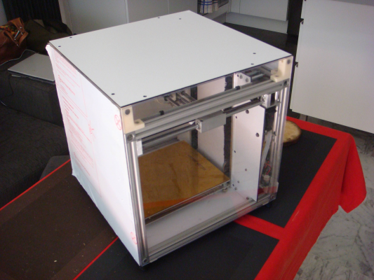
It's a Cube of 400mm x 400mm x 400mm. NOTHING are out of this frame :-D (only power supply), with a printing area of 220mm x 220mm x 215mm (I can add 10mm on each axis but I don't care...)
And it's a full enclosure :-D
(And it's WIFI enabled )
)
I will post some picture quickly.
Edited 1 time(s). Last edit at 07/26/2014 01:54PM by zelogik.
Before done that I made a simulation on inventor at work. If the Z axis have a weight of 1kilos, if I add 2kilos on the printing table in the center, the both 12mm rod bend and the Z table down from 0.005mm (near each limit) to 0.08mm in the center of the rod (at 100mm). (distance on Z at opposite of 12mm Z rod).
And in conclusion I don't see problem, even makerbot, ultimaker and some stratasys us that, and each have pretty good result.
But i'm here to say that my printer is near to be finishhhhhhhhh.
It's a Cube of 400mm x 400mm x 400mm. NOTHING are out of this frame :-D (only power supply), with a printing area of 220mm x 220mm x 215mm (I can add 10mm on each axis but I don't care...)
And it's a full enclosure :-D
(And it's WIFI enabled
 )
)I will post some picture quickly.
Edited 1 time(s). Last edit at 07/26/2014 01:54PM by zelogik.
|
Re: Atfer Hbot, go to CoreXY. July 29, 2014 08:03AM |
Registered: 9 years ago Posts: 3 |
I finally decided on the size of the exrusions It will be 360 mm horizontal and 400 mm vertical. This gives a nice 40 cm cube. I'll give the "add+20mm-Drill-Hole-and-connect-to-center-M6-opposite-profile" option a try. Although I will probably use 10mm.
I ordered the extrusions and two 12mm h6, ground and hardened shafts. Also the F624zz and LM12UU bearings are ordered.So hopefully I can build something next week.
I ordered the extrusions and two 12mm h6, ground and hardened shafts. Also the F624zz and LM12UU bearings are ordered.So hopefully I can build something next week.
|
Re: Atfer Hbot, go to CoreXY. July 29, 2014 08:19AM |
Registered: 12 years ago Posts: 199 |
@sammy66 that is the same size a my printer. Nice to see another build, keep us updated. The 20mm is actually an error. This was mend for 40mm extrusions. So 10mm should be the size to use.
Hope you have better luck with your LM12UU bearings. Mine were send twice and returned to sender for some reason. After that we agreed to cancel the order, and I had to order them somewhere else. This time it was just a few days.
Hope you have better luck with your LM12UU bearings. Mine were send twice and returned to sender for some reason. After that we agreed to cancel the order, and I had to order them somewhere else. This time it was just a few days.
|
Re: Atfer Hbot, go to CoreXY. July 31, 2014 07:47AM |
Registered: 11 years ago Posts: 112 |
As I am having both H-Bot and Corexy, I appreciate much more the H-Bot for the fluidity of the move.
I am using the same Marlin firmware for both. The H-bot is a Bowden 1.75 style extruder and for the Corexy I use a the same extruder as Jand, a Greg with 3mm filament.
I print much faster with the H-bot with less noise, and my print are perfect..
Ok, I am on my first print on the Corexy, so some adjustment might improve my first tough. Maybee due to the heavyness of the Greg extruder ?
|
Re: Atfer Hbot, go to CoreXY. August 02, 2014 12:30PM |
Registered: 9 years ago Posts: 2 |
|
Re: Atfer Hbot, go to CoreXY. August 13, 2014 08:40AM |
Registered: 10 years ago Posts: 341 |
Latest version, nearly 20% less plastic than previous version. Separated and flipped the motors, removed the tensioner bearings, so now the belts can be tensioned by sliding the motor mount along the slot. Moved the z-rods down to the next bar to gain more z height, i had 500mm sides so now i get 275mm build height.
|
Re: Atfer Hbot, go to CoreXY. August 15, 2014 07:49AM |
Registered: 9 years ago Posts: 7 |
|
Re: Atfer Hbot, go to CoreXY. August 16, 2014 04:46AM |
Registered: 9 years ago Posts: 1,159 |
Quote
marcossf
One question to all of you
Where to buy shoulder screws (4mm and 5mm shoulder diameter and 25 mm shoulder long)?? I was unable to find everywhere and also its hard to find on internet.
Marcoss try Stainless hardware from UK
Hope this helps I have used them for most of my Screws and they are very good and quick.
Doug
|
Re: Atfer Hbot, go to CoreXY. August 16, 2014 04:56AM |
Registered: 11 years ago Posts: 225 |
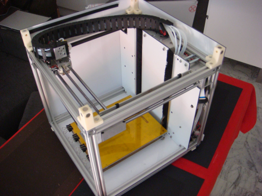
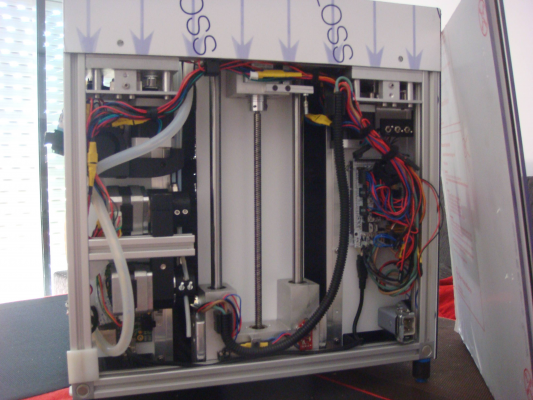
As promise some photos of the printer.
Almost finished printer :-D
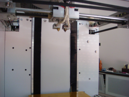
Dual nozzle (one for PLA/Soft filament and the other for ABS/High temperature filament..):
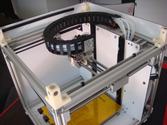
Top view of the cable chain:
Rear view, need to clean cables near the ramps system
Full enclosure, mount & dismount = 5sec (thanks to magnets)
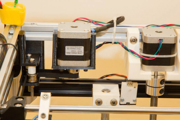
@sdavi: Nice, my first plan was to make rectangular hole ("trou oblong" in french) for fixating the motor.But it's more difficult to tight the belt with this system than a bearing like real "industrial" system.
@14thCarrot: Yes it's 12mm rod for the Z axis.
@ybm: Of course than adding an extruder on your printer make it noisier instead of a bowden system less heavier.
Edited 1 time(s). Last edit at 08/16/2014 04:57AM by zelogik.
Almost finished printer :-D
Dual nozzle (one for PLA/Soft filament and the other for ABS/High temperature filament..):
Top view of the cable chain:
Rear view, need to clean cables near the ramps system

Full enclosure, mount & dismount = 5sec
 (thanks to magnets)
@sdavi: Nice, my first plan was to make rectangular hole ("trou oblong" in french) for fixating the motor.But it's more difficult to tight the belt with this system than a bearing like real "industrial" system.
@14thCarrot: Yes it's 12mm rod for the Z axis.
@ybm: Of course than adding an extruder on your printer make it noisier instead of a bowden system less heavier.
Edited 1 time(s). Last edit at 08/16/2014 04:57AM by zelogik.
|
Re: Atfer Hbot, go to CoreXY. August 16, 2014 05:08AM |
Registered: 9 years ago Posts: 1,159 |
Hi all Been following this thread for a while and am under way with my own build which is going to be 660x660x660 outside using 30x30 type B extrusion from Motodis,
this will give 600x600x600 internal and will use 16mm rods for the Y axis 12mm rods for the Z axis (X4 1 in each corner) and 10 mm rods for the X Axis.
Will be using a E3D Kraken 4 head hotend with Bowden Extruders Nema 23 on the Z
(due to the weight of the bed which is 500x500 sq with a 400x400x6 thick Aluminium bed heated with 20 x 12 ohm 25 watt resistors arranged to give 60 ohms which will be 240V AC Fed via a SSR)
Nema17's on all other axis and will probably use either a Duet+Duex controller or a X3 Pro
Have got some of the frame assembled and the Z frame hope to get the full frame assembled with the carriages later today and will post some Pictures then.
Doug
|
Re: Atfer Hbot, go to CoreXY. August 16, 2014 11:34AM |
Registered: 9 years ago Posts: 1,159 |
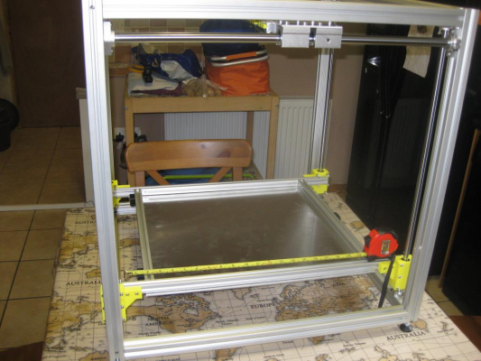
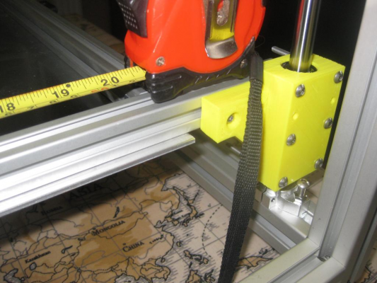
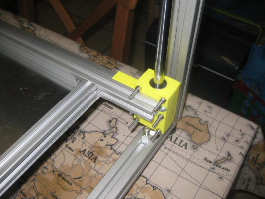
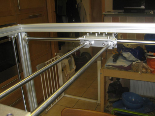
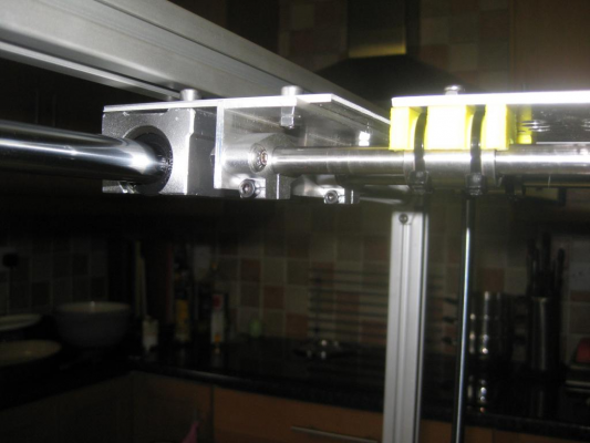
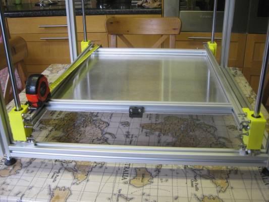
Well here is the photos of the assembled Frame and Carriages.
Think I may have to re-think the Y carriages as they take up to much room
Any Comments welcome
Got the Y carriage prob sorted simple really turn the X Carriage upside down so it Hangs from rather than sits on the rails gives me the full 400 mm + of movement to cope with all 4 extruder hot ends.
Happier now just need to square everything up. add the belt guides and motors and decide on the electronics.
Edited 1 time(s). Last edit at 08/18/2014 05:26AM by dougal1957.
|
Re: Atfer Hbot, go to CoreXY. August 17, 2014 01:27PM |
Registered: 10 years ago Posts: 553 |
|
Re: Atfer Hbot, go to CoreXY. August 18, 2014 02:51AM |
Registered: 9 years ago Posts: 1,159 |
Not in the 16mm diam Y carriage and there is so little weight on the X that the 10mm rod is pretty solid also so No. don't think there would be with 8 mm rod to be honest
But I am still not happy with the Y Carriages
Wonder if JLAND if you read this is there any chance you could modify your STL's for me to take LM16UU bearings (28mm outside diameter and 10mm dia Rods for the X spaced at 76mm.)
I am still trying to get my head around the various Cad packages
I am starting to get somewhere with Freecad but it is a slow learning curve.
Wish I could find someone local to me that uses it cos a demonstration is far better then reading tutorials!
Doug
p.s Have managed to redesign the XY Carriages using freecad so hopefully they will work (Got one side printed) have also done a X Carriage to take LM10LUU Bearings and the E3D Kraken Quad extruder hot end so not to bad off now unfortunately funds are getting low so maybe the Electronics this month so I can at least get the motions going and then the Kraken next month!
Edited 1 time(s). Last edit at 08/19/2014 11:39AM by dougal1957.
|
Re: Atfer Hbot, go to CoreXY. August 19, 2014 02:14PM |
Registered: 12 years ago Posts: 199 |
@Doug redesigning for ML16UU bearings is not so easy. Just making the holes bigger will not work, because there is not enough plastic to hold the bearings and the rods, So the motor-block, motor-block-top, idler-block, idler-block-top, XY-block and XY-block-top have to be changed and everything has to be carefully aligned again.
This is a lot of work. Also because FreeCAD is not very helpful here. It is probably faster to make each object from scratch rather than trying to modify them.
A 16mm smooth rod will not fit in the same position as the 8mm rod. This will give only 2 mm space between the bar and the outside of the frame. This is probably OK, but the bearing with the holder will stick outside the frame, so the position also has to change too.
If you don't mind sticking parts outside the frame you may get away with making the holes bigger in the motor-blocks and hope the the plastic around the rod is strong enough. Then you only have to redesign the XY-block. That is doable.
PS: if you have questions about how a specific part was made just ask.
Edited 1 time(s). Last edit at 08/19/2014 02:26PM by jand.
|
Re: Atfer Hbot, go to CoreXY. August 19, 2014 05:13PM |
Registered: 9 years ago Posts: 1,159 |
@Jland
Yes I realise that Now however I think I am there with this as I have managed to get things to look right (I am using 30x30 extrusion for the frame.)
I have managed to re-do the XY Blocks and they seem ok and also the X carriage to accommodate the X3D Kraken block (which is very small).
so hopefully good to go just need to make sure all the idler's are aligned correctly.
Doug
PS will keep the thread upto date with progress!
Edited 1 time(s). Last edit at 08/19/2014 05:14PM by dougal1957.
|
Re: Atfer Hbot, go to CoreXY. August 20, 2014 12:39AM |
Registered: 12 years ago Posts: 199 |
|
Re: Atfer Hbot, go to CoreXY. August 30, 2014 10:11PM |
Registered: 10 years ago Posts: 140 |
|
Re: Atfer Hbot, go to CoreXY. September 01, 2014 02:38AM |
Registered: 12 years ago Posts: 199 |
|
Re: Atfer Hbot, go to CoreXY. September 01, 2014 12:36PM |
Registered: 10 years ago Posts: 140 |
|
Re: Atfer Hbot, go to CoreXY. September 01, 2014 02:12PM |
Registered: 12 years ago Posts: 199 |
Correct, to get 50mm more in Z you need to increase the 400mm extrusions and the leadscrew by 50 mm.
You also have to increase the Z smooth bars by 50mm, or you add another 360mm extrusion just below the motor blocks and move the Z-axis clamps to this extrusion.
Oeps, the values have to go down by one line, I just did the correction. Did you find any more errors in the BOM?
|
Re: Atfer Hbot, go to CoreXY. September 01, 2014 02:52PM |
Registered: 10 years ago Posts: 140 |
|
Re: Atfer Hbot, go to CoreXY. September 01, 2014 03:38PM |
Registered: 12 years ago Posts: 199 |
Quote
3DRapidClone
None that I can see. Do you have a list of which printed parts use which size screw? Or is it just trial and error?
Have a look in the second sheet in BOM.ods (M3 and M4) Which is the source for the numbers in the first sheet. It shows the number of screws/nuts/washers per part. This makes the trial and error a bit smaller
|
Re: Atfer Hbot, go to CoreXY. September 01, 2014 03:56PM |
Registered: 10 years ago Posts: 140 |
|
Re: Atfer Hbot, go to CoreXY. September 01, 2014 04:11PM |
Registered: 12 years ago Posts: 199 |
In the middle of the sheet (Column Q) you see for instance 'Motor-block' (Q5) the number in the next column (R5) in the number of motor-blocks you need in the printer. (Two in this case)
When you want to know how many T-nuts you need for one motor block look at the left column (B5) so 4 nuts per motor-block.
The number at the right (C5) gives the total number of T-nuts for the two motor-blocks.
And so on for the next rows (parts).
The number at the bottom of the row (C18) is the total number of T-nuts needed. This number is filled in at the first sheet (Overview)
Hope this makes some sense?
|
Re: Atfer Hbot, go to CoreXY. September 01, 2014 04:17PM |
Registered: 10 years ago Posts: 140 |
|
Re: Atfer Hbot, go to CoreXY. September 01, 2014 11:05PM |
Registered: 9 years ago Posts: 15 |
|
Re: Atfer Hbot, go to CoreXY. September 01, 2014 11:07PM |
Registered: 10 years ago Posts: 140 |
|
Re: Atfer Hbot, go to CoreXY. September 02, 2014 12:45AM |
Registered: 12 years ago Posts: 199 |
|
Re: Atfer Hbot, go to CoreXY. September 02, 2014 12:00PM |
Registered: 12 years ago Posts: 1,450 |
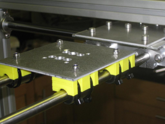
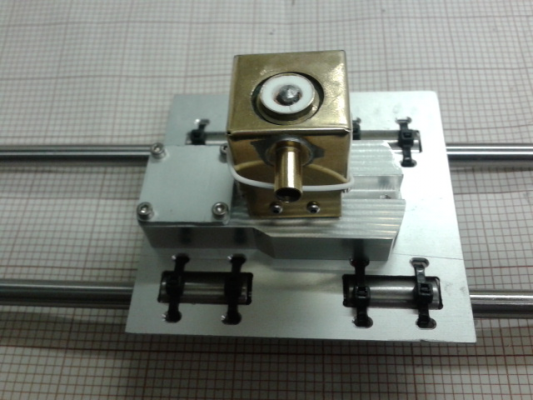
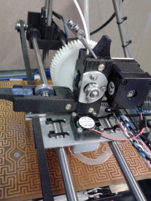
I was lurking through this thread and noticed the August16 posting from dougal1957 where one photo shows a carriage made from a plate with a comment "Think I may have to re-think the Y carriages as they take up to much room". Possibly these may be of help to him and anybody else that finds the idea helpful.
The square cutouts, in this case in 2mm hard aluminium, have chamfers for the LM8UU bearings to rest on.
Mike
The square cutouts, in this case in 2mm hard aluminium, have chamfers for the LM8UU bearings to rest on.
Mike
Sorry, only registered users may post in this forum.
