CoreXY construction details
Posted by polyglot
|
CoreXY construction details September 26, 2014 10:45AM |
Registered: 9 years ago Posts: 42 |
I'm pondering building a CoreXY+Z system and have a couple questions that I'm hoping you can help with.
Does anyone know of an affordable source of GT2 idler pulleys? With shipping to Australia? The only ones I see on eBay are $15 each shipped and I need lots of them.
If not, does anyone know of an easy way to hack up an idler with flanges (to stop the belt wandering off the sides), e.g. from a couple of washers? Otherwise I think I'll be spending a day in front of the lathe and machining a bunch out of Delrin to press-fit onto 608ZZs and then stacking that onto a shoulder bolt above a spacer. The price is right but it's a lot of work.
The majority (8 of 10) of the pulleys on a CoreXY basic stage are in contact with the cogged side of the belt. Will it cause undue tooth wear to use smooth idlers instead of using cogged pulleys as idlers? See the corexy-invert.jpg attachment which shows a CoreXY with the belt inverted (cogs facing outwards). It uses two extra idlers but now we have 10 idlers on the back of the belt and just two touching the face of the belt, compared with 8 idlers touching the face and 2 touching the back. My intuition is that this should result in greatly reduced belt tooth wear on the parts of the belt that the motor pulleys frequently traverse and therefore less frequent belt replacements.
Has anyone tried this inverted belt configuration? I don't know that the back of the belt is designed to be a wear surface like the teeth are though, so that concerns me a little.
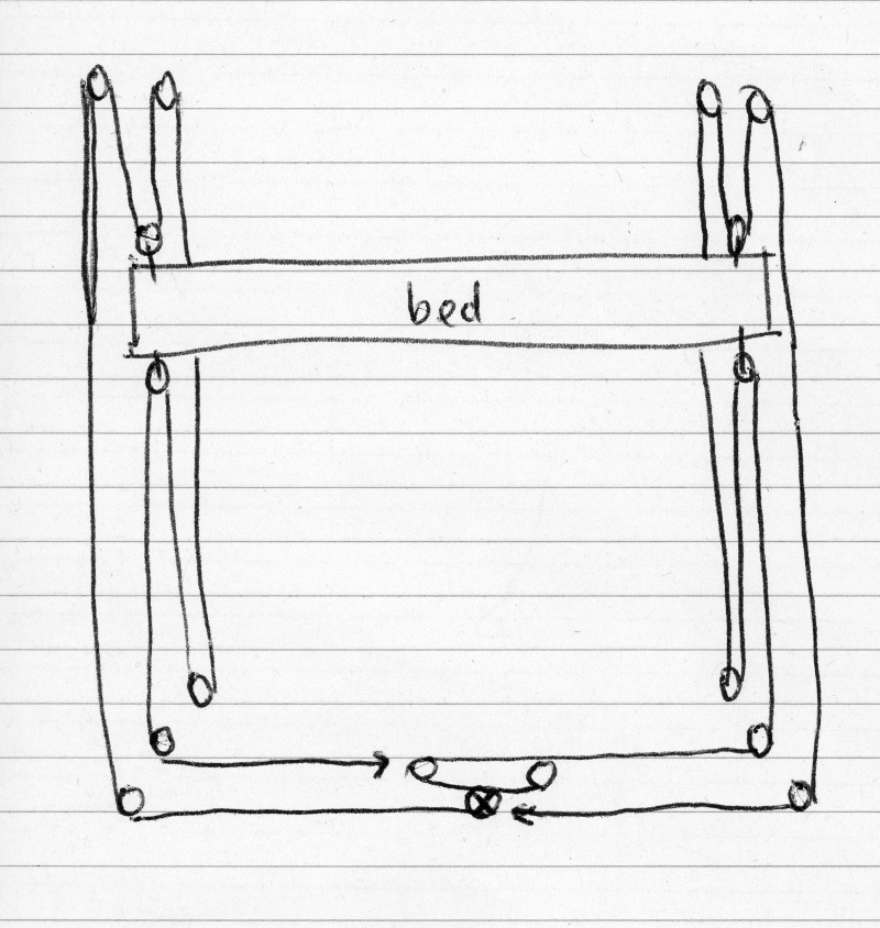
For Z, consider the attached chicken-scratching (triple-z.jpg), which describes the Z mechanism for one side of the bed, with tripled pulleys for more lifting force and finer movements. The "motor" pulley at bottom centre is actually four pulleys on a 5mm ground shaft that runs across the width of the machine. It's drawn in the classic configuration of teeth-inwards but could be inverted just like the XY stage without needing extra pulleys because the motor is already in an S-bend; the inverted config would have only 4 idlers (the ones on the bed) touching belt teeth, and they will wear on a very small section of belt with little or no overlap with the section used by the motor.
My arrangement depends on torsion of the ground rod (8mm would be an easy choice) to keep the bed straight+level. Do you expect it to be more or less stable than a bed which has just a single Z drive knot (per the diagram) in the XZ plane and is supported in the YZ plane by a pair of classic moving knots depicted in [www.corexy.com] ?
Any opinions? Stupidities? Stuff I should have thought of but didn't?
Edited 1 time(s). Last edit at 09/26/2014 10:46AM by polyglot.
Does anyone know of an affordable source of GT2 idler pulleys? With shipping to Australia? The only ones I see on eBay are $15 each shipped and I need lots of them.
If not, does anyone know of an easy way to hack up an idler with flanges (to stop the belt wandering off the sides), e.g. from a couple of washers? Otherwise I think I'll be spending a day in front of the lathe and machining a bunch out of Delrin to press-fit onto 608ZZs and then stacking that onto a shoulder bolt above a spacer. The price is right but it's a lot of work.
The majority (8 of 10) of the pulleys on a CoreXY basic stage are in contact with the cogged side of the belt. Will it cause undue tooth wear to use smooth idlers instead of using cogged pulleys as idlers? See the corexy-invert.jpg attachment which shows a CoreXY with the belt inverted (cogs facing outwards). It uses two extra idlers but now we have 10 idlers on the back of the belt and just two touching the face of the belt, compared with 8 idlers touching the face and 2 touching the back. My intuition is that this should result in greatly reduced belt tooth wear on the parts of the belt that the motor pulleys frequently traverse and therefore less frequent belt replacements.
Has anyone tried this inverted belt configuration? I don't know that the back of the belt is designed to be a wear surface like the teeth are though, so that concerns me a little.
For Z, consider the attached chicken-scratching (triple-z.jpg), which describes the Z mechanism for one side of the bed, with tripled pulleys for more lifting force and finer movements. The "motor" pulley at bottom centre is actually four pulleys on a 5mm ground shaft that runs across the width of the machine. It's drawn in the classic configuration of teeth-inwards but could be inverted just like the XY stage without needing extra pulleys because the motor is already in an S-bend; the inverted config would have only 4 idlers (the ones on the bed) touching belt teeth, and they will wear on a very small section of belt with little or no overlap with the section used by the motor.
My arrangement depends on torsion of the ground rod (8mm would be an easy choice) to keep the bed straight+level. Do you expect it to be more or less stable than a bed which has just a single Z drive knot (per the diagram) in the XZ plane and is supported in the YZ plane by a pair of classic moving knots depicted in [www.corexy.com] ?
Any opinions? Stupidities? Stuff I should have thought of but didn't?
Edited 1 time(s). Last edit at 09/26/2014 10:46AM by polyglot.
|
Re: CoreXY construction details September 26, 2014 11:29AM |
Registered: 9 years ago Posts: 42 |
Oooh, 2 of 604ZZ flanged bearings stacked ought to make a nice flat idler. And a stack of three or so MR84ZZ inside a toothed pulley with 8mm bore ought to make a passable toothed idler.
Still seeking opinions on the inverted belt configuration and the relative merits of moving knot vs torsion bar for keeping the bed straight.
Still seeking opinions on the inverted belt configuration and the relative merits of moving knot vs torsion bar for keeping the bed straight.
|
Re: CoreXY construction details September 26, 2014 12:20PM |
Registered: 9 years ago Posts: 1,159 |
try Robotdigg.com for toothed pulleys and belts he is very cheap (Approx $2 US each)
20 tooth GT2 pulley 8mm bore
20 tooth GT2 pulley 8mm bore
|
Re: CoreXY construction details September 26, 2014 12:22PM |
Registered: 9 years ago Posts: 1,159 |
Also see After H-Bot go Core XY
|
Re: CoreXY construction details September 26, 2014 07:34PM |
Registered: 9 years ago Posts: 23 |
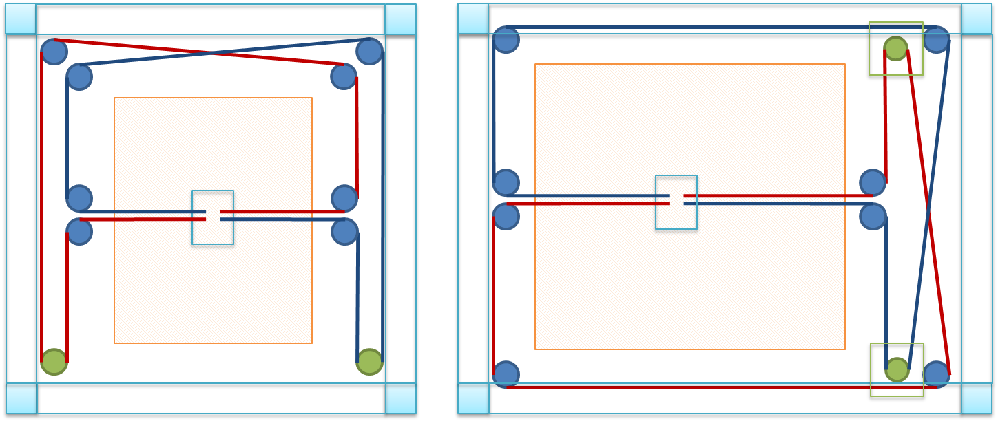
I think that your proposed inverted XY design has merit. I've been working on something very close to that configuration for a couple of months. Basically, I rotated the crossover 90 degrees so that it was on the side, and then rotated the motors 90 degrees so that they were on the same side. So if you move the stepper motors to where your right inside idler bearing is and eliminate the extra idler for the motor, the setups would be the same. Then if you rotate the belts at the crossover 180 degrees, it not only helps them cross without using two levels, it also makes it so that only the back of the belt runs on the idlers. No GT2 idlers are necessary. For a given footprint, I think this design will give more print area.
I've got my design framed up and I'm printing some of the carriages now, but it will probably be about two weeks before I get around to running tests. To keep the belts on the idler bearing, I'm just printing some spacers. I don't know if they will work yet.
I've got my design framed up and I'm printing some of the carriages now, but it will probably be about two weeks before I get around to running tests. To keep the belts on the idler bearing, I'm just printing some spacers. I don't know if they will work yet.
|
Re: CoreXY construction details September 26, 2014 09:42PM |
Registered: 9 years ago Posts: 42 |
Thanks for the robotdigg link, it looks like they're the upstream supplier from our local shop and half the price on everything 
I also hadn't thought of twisting belts. Taking rcengr's diagram on the right and putting a twist in the belts where they cross would mean all idlers running on the back of the belt and no extra idlers required. Twisting the belt next to the motor worries me a bit though because it will be going onto the pulley slightly funny and I would expect more wear on the tooth edges.
I also hadn't thought of twisting belts. Taking rcengr's diagram on the right and putting a twist in the belts where they cross would mean all idlers running on the back of the belt and no extra idlers required. Twisting the belt next to the motor worries me a bit though because it will be going onto the pulley slightly funny and I would expect more wear on the tooth edges.
|
Re: CoreXY construction details September 26, 2014 11:56PM |
Registered: 10 years ago Posts: 229 |
Or you could just look on Ebay - [www.ebay.com]]
And 5M GT2 belt - [www.ebay.com]
The pulley is $2.01 cheaper than robotdigg after you figure in the shipping (quoted me $4.00 shipping on one pulley!!) They look like they have cheap prices, but bend you over and rape you raw on shipping charges. I saved over $30.00 NOT buying from them when I built my Smartrap, and in several cases I got a better quality part than what they were selling. So... Not a fan of robotdigg here. Regardless, if your budget minded, it can pay to shop around a bit.
I am looking at a CoreXY for my next printer. I have and really like my Smartrap, but would like to have a larger build area and I like the concept of the CoreXY.
@ rcengr - I like your idea of belt routing scheme. but don't you end up with an extra bar in there for the Y axis? I'll have to give it some thought as I work on my design. I have the limitation of needing all the parts be able to print out on my little Smartrap. That, and I want to try to keep the cost to bare minimum and still have a reliable and accurate printer.
Edited 2 time(s). Last edit at 09/26/2014 11:58PM by markstephen.
From FreeCAD To The Real World- Demo video using FreeCAD and featuring the Smartrap 3D Printer
|
Re: CoreXY construction details September 27, 2014 10:50AM |
Registered: 9 years ago Posts: 42 |
|
Re: CoreXY construction details September 27, 2014 01:30PM |
Admin Registered: 11 years ago Posts: 3,096 |
Got my stuff from Robotdigg.. Man, they are just up to standards! No quality flaws in any part, the only thing that didn't work were the small 8mm posts. They were too thick, but only by a few micron. I had no tools to grind them down, so I decided to find another solution.
Sadly there is a problem with my frame and I have not been able to fix this due to working on my thesis for my graduation year at the art academy. The bronze bushings somehow are not rolling smooth enough and I am seriously doubting to go on with bronze bushings. I had such great fantasies of using bronze bushings, but linear ball bearings are just so much easier and they don't mind a 0.01mm incorrectness
http://www.marinusdebeer.nl/
|
Re: CoreXY construction details September 28, 2014 01:15AM |
Registered: 9 years ago Posts: 42 |
Quote
Ohmarinus
the only thing that didn't work were the small 8mm posts. They were too thick, but only by a few micron. I had no tools to grind them down, so I decided to find another solution.
They're probably expecting you to press them into bearings using a bearing press. It's meant to be an interference fit.
|
Re: CoreXY construction details September 28, 2014 01:10PM |
Admin Registered: 11 years ago Posts: 3,096 |
They are these:
[www.robotdigg.com]
I tried to fit the F608ZZ on them, but would not fit, not even with a press. It's too tight. When I emailed them about the problem they told me to slightly sand them down. Ehhh yeah, no.
So now I got some brass rods that I use as a rod to fit the smaller flanged 624 bearings on works even better, less mass and the belts fit exactly in between two of those.
Edited 1 time(s). Last edit at 09/28/2014 01:11PM by Ohmarinus.
http://www.marinusdebeer.nl/
[www.robotdigg.com]
I tried to fit the F608ZZ on them, but would not fit, not even with a press. It's too tight. When I emailed them about the problem they told me to slightly sand them down. Ehhh yeah, no.
So now I got some brass rods that I use as a rod to fit the smaller flanged 624 bearings on
works even better, less mass and the belts fit exactly in between two of those.Edited 1 time(s). Last edit at 09/28/2014 01:11PM by Ohmarinus.
http://www.marinusdebeer.nl/
Sorry, only registered users may post in this forum.