Openbeam CoreXY in Construction
Posted by RepRot
|
Openbeam CoreXY in Construction September 29, 2014 11:20PM |
Registered: 14 years ago Posts: 128 |
Hi,
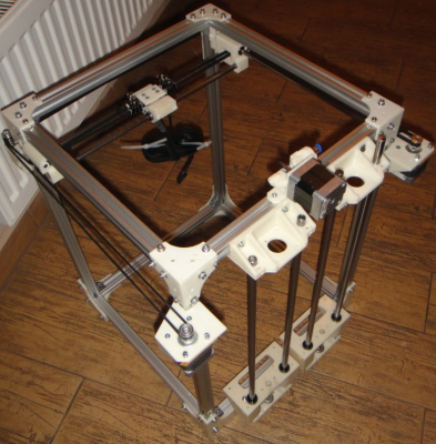
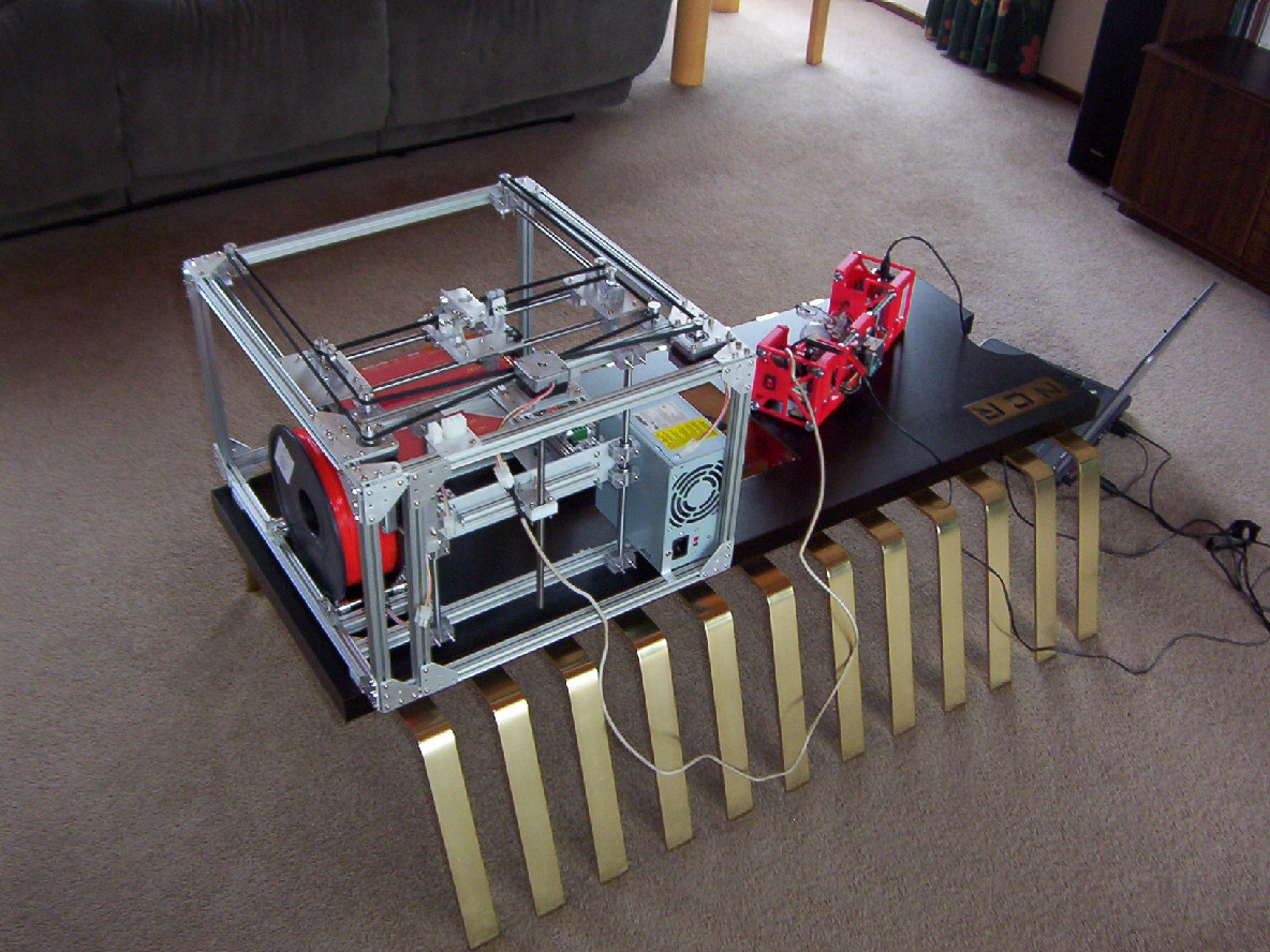
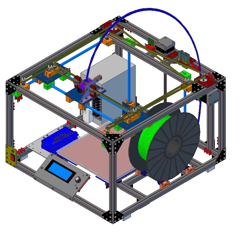
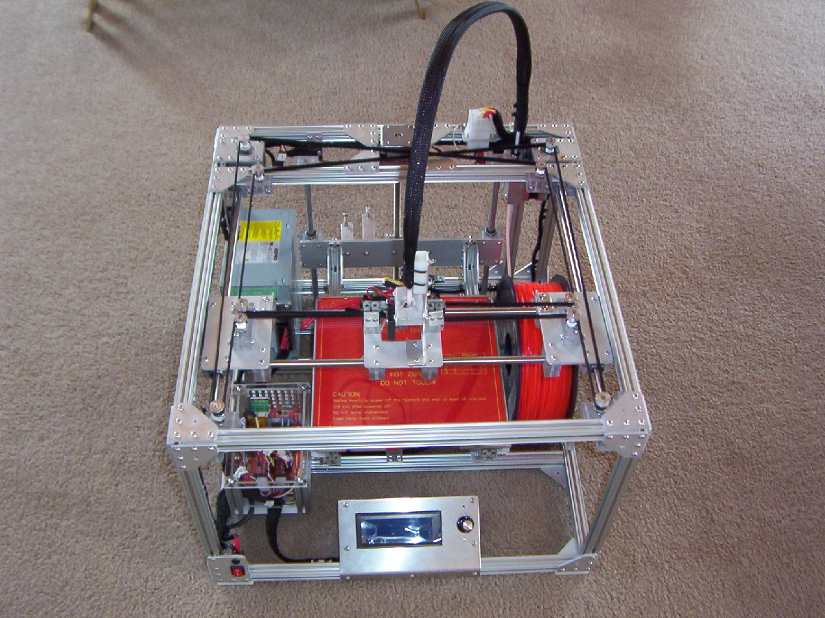
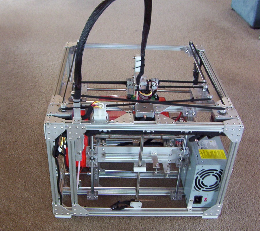
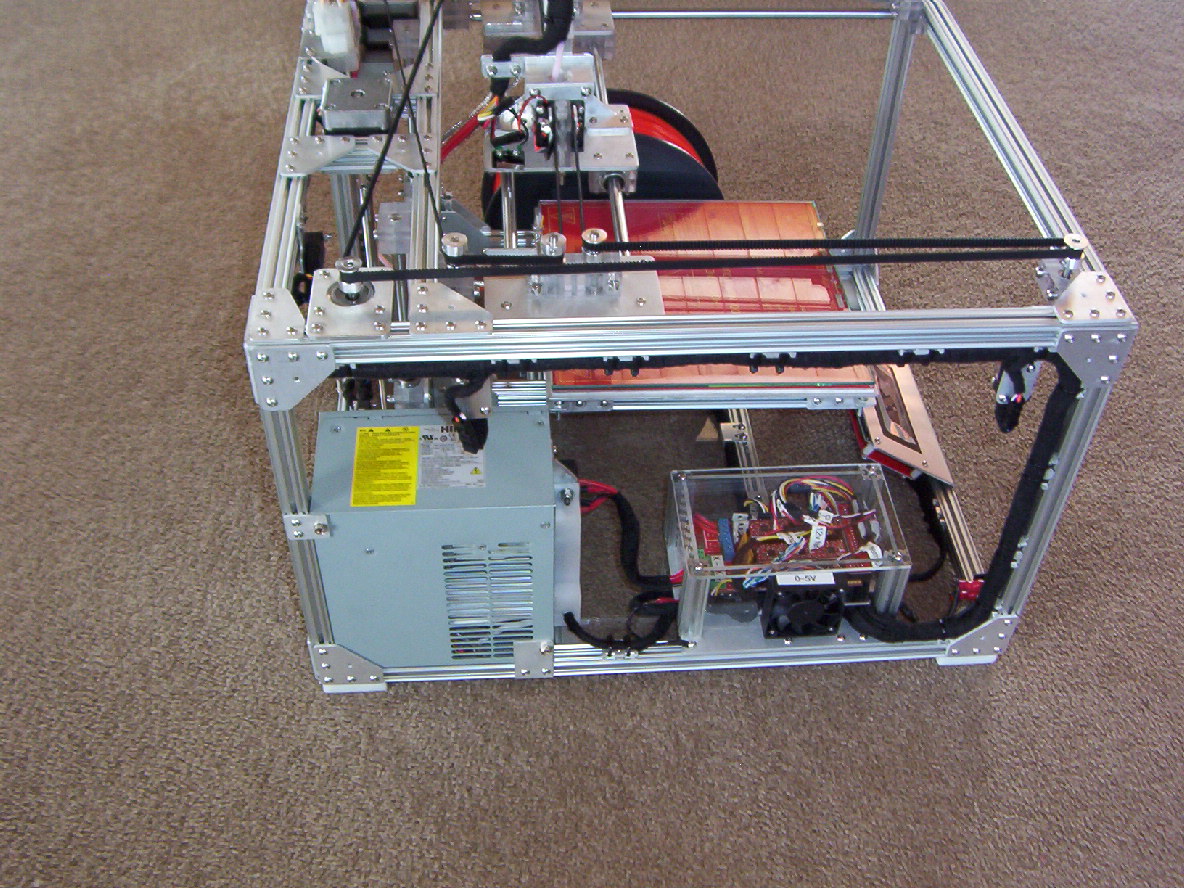
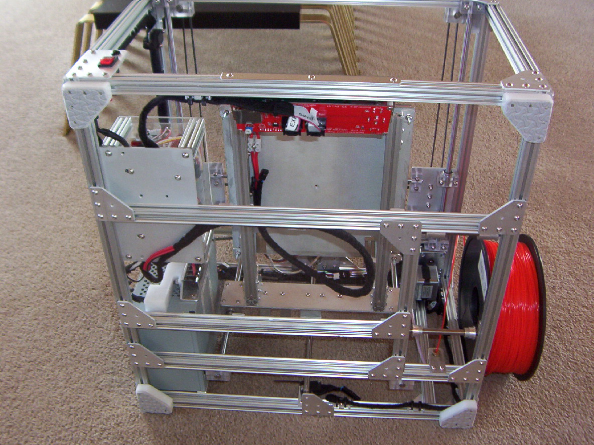
Some pictures of a CoreXY Openbeam I have designed and currently building in Rotorua, New Zealand.. A good few hours on the CAD program....
Still got to source a bulk lot of screws and nuts and a Bowden extruder head assembly. Then I will do the final assembly. (Currently using temporary screws and nuts. The nuts I had don't fit the Openbeam extrusions).
Still finishing the extruder motor assembly, need to drill and thread a couple of holes for the filament (1.75mm) . Will properly need to source a larger Nema17 motor than what I currently have.
Used my golf ball printer (eggbot) to test that the Z drive as the print platform is quite heavy. Using Nema17 (32mm long) Ex ATM money machine, seems to work good and doesn't slip.
Had the Openbeam corner brackets with a water jet cut out of 2mm Aluminium. I did a home anodising job to all the corner brackets and other Aluminium parts by using car battery sulphuric with a bench power supply.
All Pulleys are mounted with two small bearings 5x10x4 mm. Uses 11 standard 8mm linear bearings. All bearings blocks, linear shafts have been machined out of Polycarbonate.
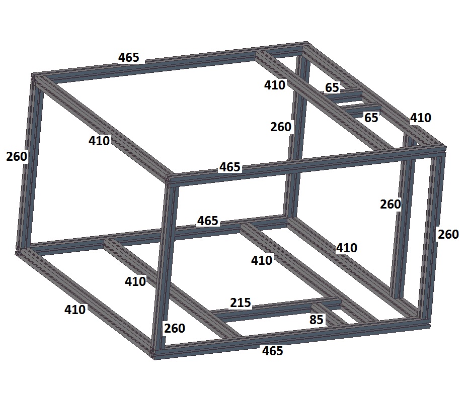
Using Openbeam extrusions makes alignment of the whole frame and pulley position very easy.
Using a standard modified ATX PC power supply. Have also allowed a +5volt output for a cooling fan as I am planning to have a cover over the Mega/ramps PCB's.
For the heated bed, I have used a aluminium plate with a 3mm ceramic pad and MK2 heater with a harden 4mm glass plate.. I would have liked 3mm but could only get 4mm. May make some changes to this design.
My main aim was to try and keep everything in the Openbeam box area except for the top area.
Have made some Aluminium pieces that can be screwed onto the Openbeam to enable cable ties to be used to keep the wiring tidy.
While it is sitting on a large IC, the print area should be 200mm x 200mm x 200mm. Print height may change subject to the head assembly I end up using.
Cheers
Some pictures of a CoreXY Openbeam I have designed and currently building in Rotorua, New Zealand.. A good few hours on the CAD program....
Still got to source a bulk lot of screws and nuts and a Bowden extruder head assembly. Then I will do the final assembly. (Currently using temporary screws and nuts. The nuts I had don't fit the Openbeam extrusions).
Still finishing the extruder motor assembly, need to drill and thread a couple of holes for the filament (1.75mm) . Will properly need to source a larger Nema17 motor than what I currently have.
Used my golf ball printer (eggbot) to test that the Z drive as the print platform is quite heavy. Using Nema17 (32mm long) Ex ATM money machine, seems to work good and doesn't slip.
Had the Openbeam corner brackets with a water jet cut out of 2mm Aluminium. I did a home anodising job to all the corner brackets and other Aluminium parts by using car battery sulphuric with a bench power supply.
All Pulleys are mounted with two small bearings 5x10x4 mm. Uses 11 standard 8mm linear bearings. All bearings blocks, linear shafts have been machined out of Polycarbonate.
Using Openbeam extrusions makes alignment of the whole frame and pulley position very easy.
Using a standard modified ATX PC power supply. Have also allowed a +5volt output for a cooling fan as I am planning to have a cover over the Mega/ramps PCB's.
For the heated bed, I have used a aluminium plate with a 3mm ceramic pad and MK2 heater with a harden 4mm glass plate.. I would have liked 3mm but could only get 4mm. May make some changes to this design.
My main aim was to try and keep everything in the Openbeam box area except for the top area.
Have made some Aluminium pieces that can be screwed onto the Openbeam to enable cable ties to be used to keep the wiring tidy.
While it is sitting on a large IC, the print area should be 200mm x 200mm x 200mm. Print height may change subject to the head assembly I end up using.
Cheers
Attachments:
open | download - CoreXY Openbeam-1.JPG (339.8 KB)
open | download - CoreXY Openbeam-2.JPG (323.6 KB)
open | download - CoreXY Openbeam-3.JPG (344.6 KB)
open | download - CoreXY Openbeam-4.JPG (319.2 KB)
open | download - Openbeam CoreXY Printer-.jpg (206.6 KB)
open | download - Frame.jpg (168.7 KB)
|
Re: Openbeam CoreXY in Construction September 30, 2014 09:53AM |
Registered: 10 years ago Posts: 553 |
Looks nice! I like that everything is contained within the frame.
Are you going to put panels/enclosure on it?
greghoge.com
HUGE 3D PRINTER PARTS SALE!!!
Are you going to put panels/enclosure on it?
greghoge.com
HUGE 3D PRINTER PARTS SALE!!!
|
Re: Openbeam CoreXY in Construction September 30, 2014 04:24PM |
Registered: 12 years ago Posts: 809 |
Nice!
And awesome coffee table too!
- akhlut
Just remember - Iterate, Iterate, Iterate!
[myhomelessmind.blogspot.com]
And awesome coffee table too!
- akhlut
Just remember - Iterate, Iterate, Iterate!
[myhomelessmind.blogspot.com]
|
Re: Openbeam CoreXY in Construction September 30, 2014 11:59PM |
Registered: 14 years ago Posts: 128 |
Thanks for the good comments,
One of my aims with this design is make it a multi tool. 3D printer, laser cutter, soft material router and possibly use a high voltage electric arc to cut thin aluminium if the EMF emission doesn't take down the phone network or blow the electronics. (plasma cutter).
I have used a couple of large connector sockets at the top right rear for the electrical connections to the printhead assembly. The aim is that the head assembly (fan and printhead) is only attached with 2 screws and should be able to be removed with the cable harness quickly and replaced with a laser module. Heated bed can easy be exchanged with disconnecting electrical cables and loosening 4 screws and sliding the bed out.
Don't see it needs panels as a 3D printer unless there is a high noise issue. For other applications it would be a must with magnetic switches as interlocks..
Cheers
|
Re: Openbeam CoreXY in Construction October 01, 2014 09:51AM |
Registered: 9 years ago Posts: 376 |
|
Re: Openbeam CoreXY in Construction December 01, 2014 11:28PM |
Registered: 14 years ago Posts: 128 |
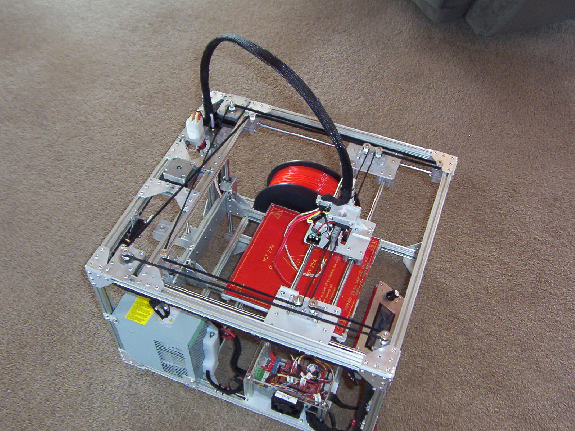
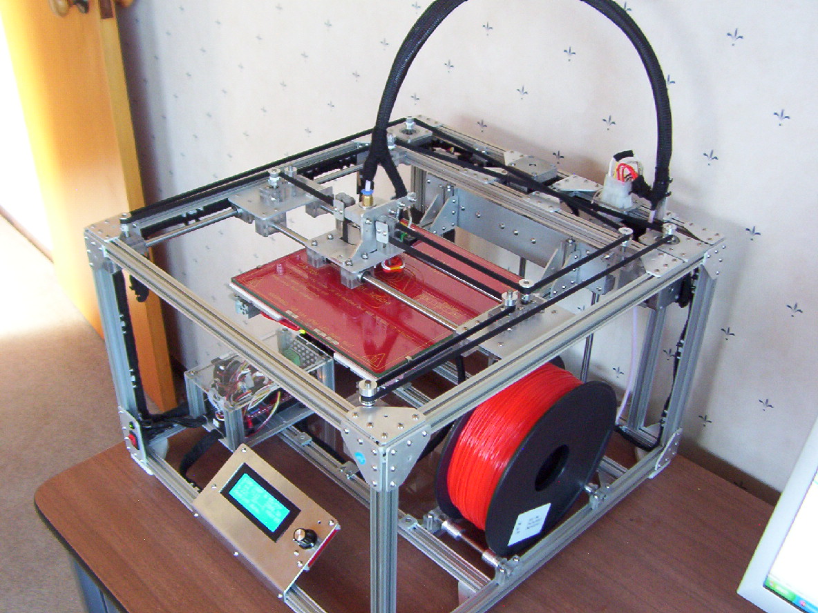
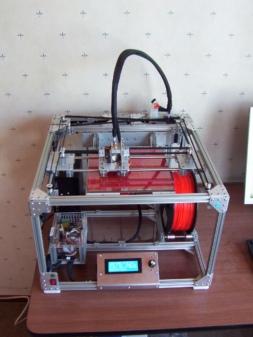
Some more pictures of my Openbeam CoreXY build..
Wiring now added with Min and Max switches on all axis. Still awaiting my hot head and bed thermistor to arrive.
I made a couple of changes with the mounting of the Z motor to allow the wiring harness to be better attached. Also it makes it easier to adjust the Z motor for better alignment.
Added two mechanical end stops on the Y axis, X axis doesn't need them, Z axis has a couple of screws that are end stops for Min position.
Mega and ramps have been housed in a box. Openbeam was used for the corner brackets and 2mm perspex sheets for the covers.
About to start testing that the ramps will work.
Cheers.
|
Re: Openbeam CoreXY in Construction December 20, 2014 05:13AM |
Registered: 10 years ago Posts: 12 |
|
Re: Openbeam CoreXY in Construction December 20, 2014 06:33PM |
Registered: 14 years ago Posts: 128 |
Hi Linuxbaba,
I used Alibre CAD, unless you have Alibre I don't think you can view the CAD pictures. I can export it to a PDF file which gives a 3D view (7.11M .
.
Sent me a PM with your email address if you would like a copy.
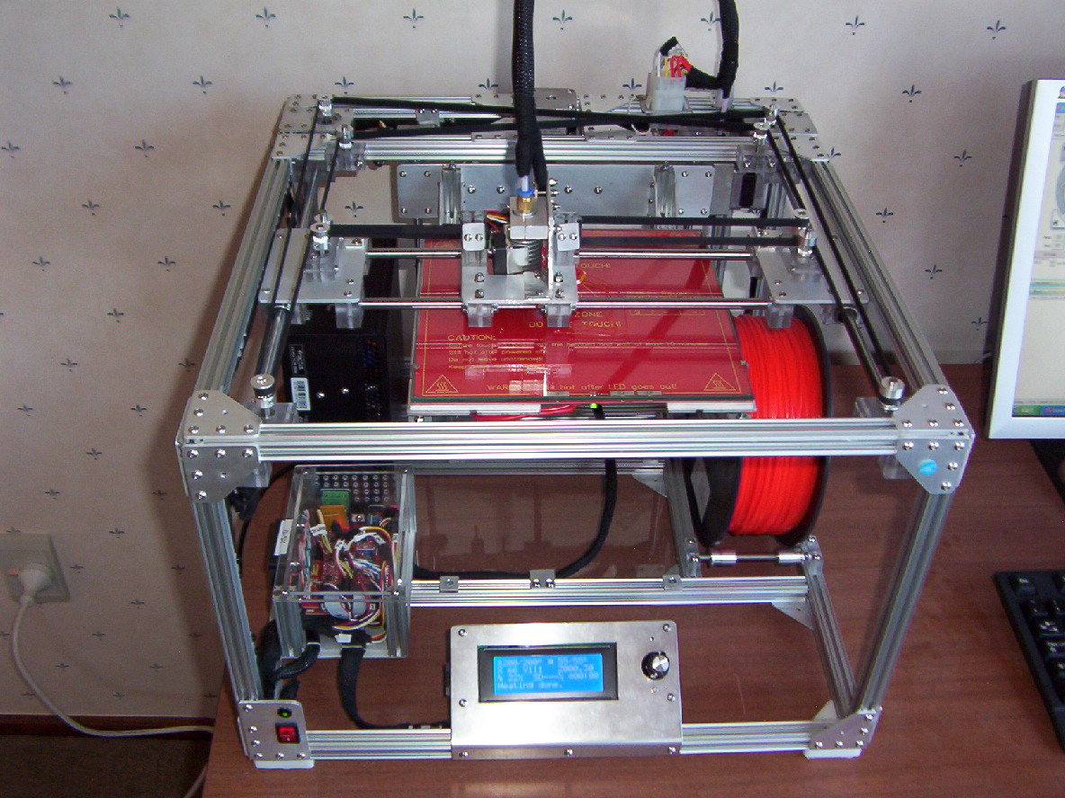
Current status...........................
I have got all the firmware working for moving the XYZ axis motors as well as the extruder motor. Using both Min and Max end stops on all three axis. SD card and LCD working.
I have a print area of 200mm (Y axis ) x 190mm(X axis) approx 200mm for the z axis. (subject to hotend).
The X axis is reduced to 190mm as I am using four Swiss clips to hold the glass plate to the head bed which is on an Aluminium plate. I don't wish to allow the hotend to hit these Swiss clips.
I had to follow up with hotend supplier as my order looks as if it has been lost in the post.
The ATX power supply that I have is rated at 18 amps for the 12 volt output. (only using 12 volts for all electronics). However I have found that the 12 volts is being pulled down to 11.5v and has dropped out when testing the hot bed. I have ordered a DC to DC converter (300watt) to see if reducing the hot bed voltage will get around this issue, no doubt it will increase the time it takes to heat the bed. If it takes too long I will get a bigger rated power supply, have already found one that I can source that will fit the space. I think that as the heat bed heats up the current draw changes. At US$6 for a converter via ebay, it may be good cheap option for others if it works. My other 3D printer (Mendel M5 battle tank- can be googled..), I used a separate AC lighting transformer with a sold state switch for the heated bed.
Cheers.
I used Alibre CAD, unless you have Alibre I don't think you can view the CAD pictures. I can export it to a PDF file which gives a 3D view (7.11M
.Sent me a PM with your email address if you would like a copy.
Current status...........................
I have got all the firmware working for moving the XYZ axis motors as well as the extruder motor. Using both Min and Max end stops on all three axis. SD card and LCD working.
I have a print area of 200mm (Y axis ) x 190mm(X axis) approx 200mm for the z axis. (subject to hotend).
The X axis is reduced to 190mm as I am using four Swiss clips to hold the glass plate to the head bed which is on an Aluminium plate. I don't wish to allow the hotend to hit these Swiss clips.
I had to follow up with hotend supplier as my order looks as if it has been lost in the post.
The ATX power supply that I have is rated at 18 amps for the 12 volt output. (only using 12 volts for all electronics). However I have found that the 12 volts is being pulled down to 11.5v and has dropped out when testing the hot bed. I have ordered a DC to DC converter (300watt) to see if reducing the hot bed voltage will get around this issue, no doubt it will increase the time it takes to heat the bed. If it takes too long I will get a bigger rated power supply, have already found one that I can source that will fit the space. I think that as the heat bed heats up the current draw changes. At US$6 for a converter via ebay, it may be good cheap option for others if it works. My other 3D printer (Mendel M5 battle tank- can be googled..), I used a separate AC lighting transformer with a sold state switch for the heated bed.
Cheers.
|
Re: Openbeam CoreXY in Construction December 21, 2014 02:57AM |
Registered: 10 years ago Posts: 12 |
|
Re: Openbeam CoreXY in Construction January 12, 2015 02:39AM |
Registered: 14 years ago Posts: 128 |
Hi Linuxbaba,
Just purchased a Fractal Tesla R2 500w power supply. Measures 150mm x 86mm x 165mm. So it fitted with no problems. Outputs up to 41 amps for the 12v supply.
Very easy to modify, needed to jump a few voltage sense wires within the power unit. I feed out 3 wires to each of the 4 ramps power connections. Very quite unit.
Hot end heats from 22 degrees C to 200 in 1.5 minutes. - Heat bed heats from 22 to 55 in 4.5 minutes (using 4mm glass plate and ceramic mat).
Got my hot end from China, ended up taking 2 months to arrive, supplier sent another one at no cost after I got back to them that it hadn't arrived. This one arrived in 1 week.
Just been testing the extruder and hot end. I was given all 4 stepper and but thought that I would need to upgrade the extruder one which has proved correct. Have ordered one which should arrive in the next couple of days.
Only thing that I may change at a later date is that with the print bed canter levered, it does have a small amount of spring, not sure whether this may be an issue, all depends on the weight of the object that is being printed. I think that the two 8mm carbon steel rods may be flexing rather than the Openbeam frame. I had planned to use 2 mm glass but only could get 4mm heat treated glass which increased the heat bed weight. If it is a problem I will look at using 10mm steel rods (50% stronger) and bigger linear bearings.
May need to do some work around the hot end to get the correct heat zone. Made a aluminium bracket for the cooling fan, not sure if its making too small heat change zone, can always move it up a bit if needed.
Will look at possibly adding a air tube from a fan fixed to the Openbeam frame to the head assembly for cooling the printed plastic once everything is printing correctly.
Happy that everything is moving and heating correctly, just need to get it feeding plastic correctly.
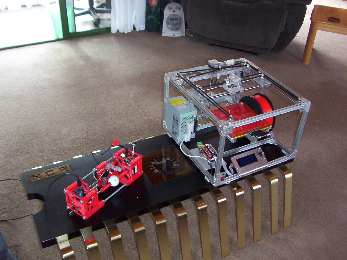
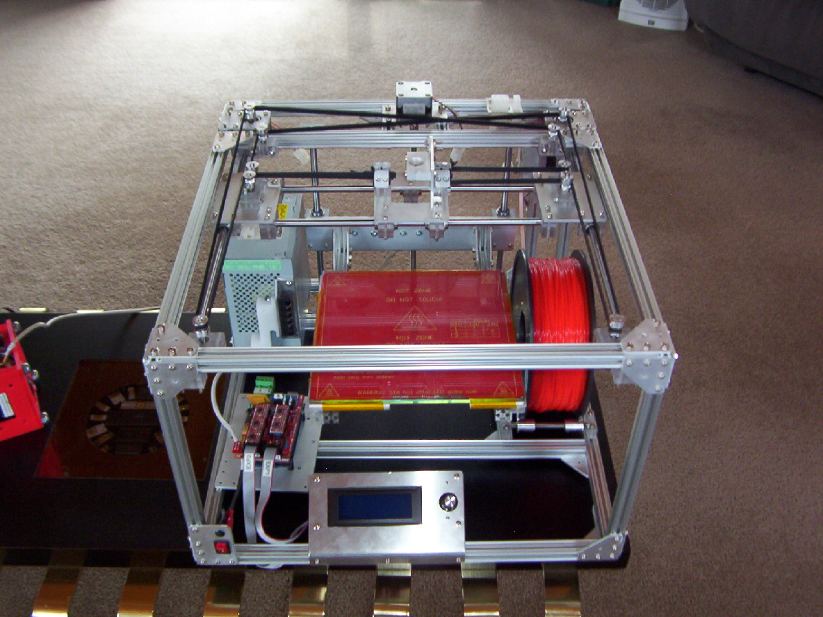
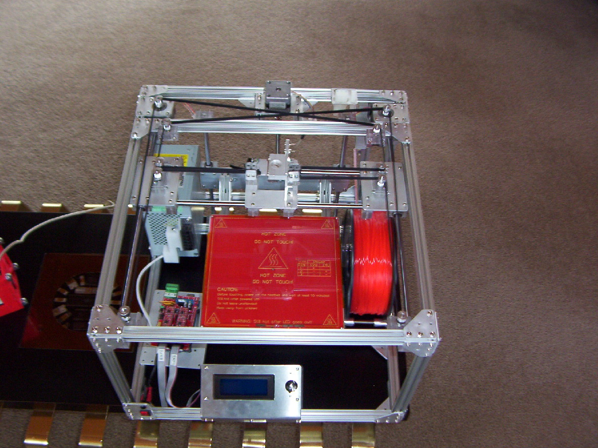
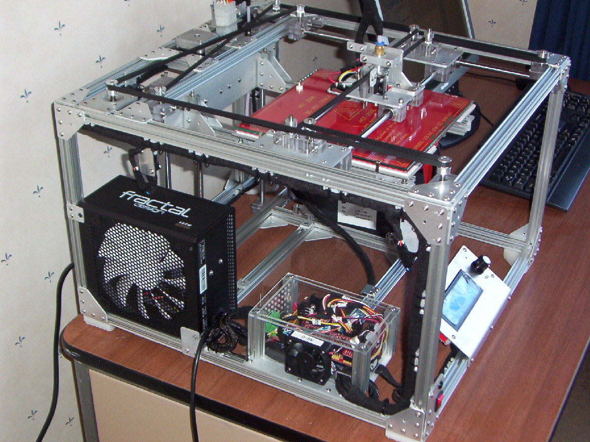
Some pictures of the current build with power supply and hot end installed.
Cheers
Just purchased a Fractal Tesla R2 500w power supply. Measures 150mm x 86mm x 165mm. So it fitted with no problems. Outputs up to 41 amps for the 12v supply.
Very easy to modify, needed to jump a few voltage sense wires within the power unit. I feed out 3 wires to each of the 4 ramps power connections. Very quite unit.
Hot end heats from 22 degrees C to 200 in 1.5 minutes. - Heat bed heats from 22 to 55 in 4.5 minutes (using 4mm glass plate and ceramic mat).
Got my hot end from China, ended up taking 2 months to arrive, supplier sent another one at no cost after I got back to them that it hadn't arrived. This one arrived in 1 week.
Just been testing the extruder and hot end. I was given all 4 stepper and but thought that I would need to upgrade the extruder one which has proved correct. Have ordered one which should arrive in the next couple of days.
Only thing that I may change at a later date is that with the print bed canter levered, it does have a small amount of spring, not sure whether this may be an issue, all depends on the weight of the object that is being printed. I think that the two 8mm carbon steel rods may be flexing rather than the Openbeam frame. I had planned to use 2 mm glass but only could get 4mm heat treated glass which increased the heat bed weight. If it is a problem I will look at using 10mm steel rods (50% stronger) and bigger linear bearings.
May need to do some work around the hot end to get the correct heat zone. Made a aluminium bracket for the cooling fan, not sure if its making too small heat change zone, can always move it up a bit if needed.
Will look at possibly adding a air tube from a fan fixed to the Openbeam frame to the head assembly for cooling the printed plastic once everything is printing correctly.
Happy that everything is moving and heating correctly, just need to get it feeding plastic correctly.
Some pictures of the current build with power supply and hot end installed.
Cheers
|
Re: Openbeam CoreXY in Construction January 15, 2015 10:50AM |
Registered: 9 years ago Posts: 2 |
|
Re: Openbeam CoreXY in Construction January 17, 2015 02:48AM |
Registered: 14 years ago Posts: 128 |
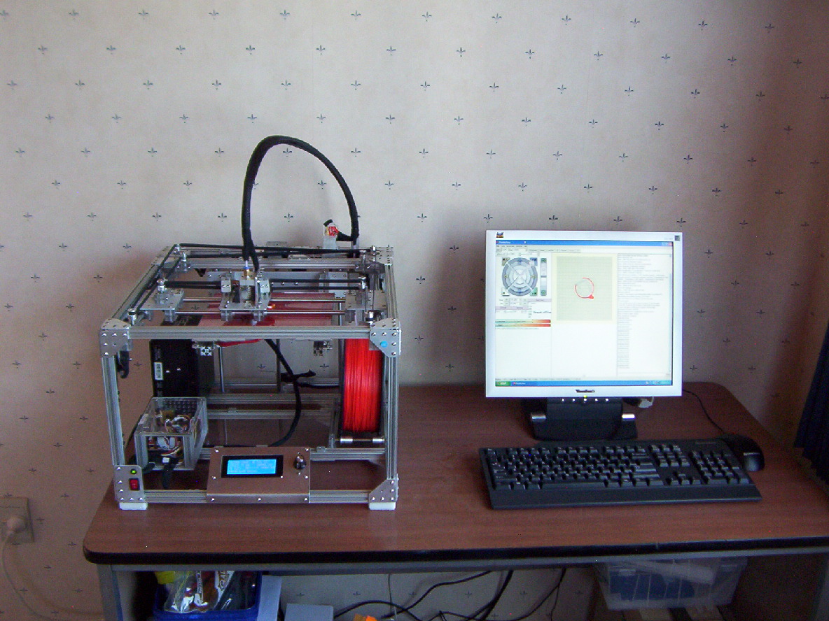
Sorry no BOM at this stage. I do have a number of drawings in Coreldraw of most of the parts. I don't have the time at present with other summer activities. Hopefully will get time in the near future.
Just starting to fine tune the printing. Using Pronterface and Slic3r.
Hotend is all metal one with no Teflon tube. Very pleased with CoreXY and have all the min and max end stops working.
Print area is
X:190mm
Y: 200mm
Z: 195 mm
Z feeds to 200mm which is when the bed sits on the bottom frame which makes it firm for removing printed objects. Due to how parallel the Openbeam bed frame is to the Openbeam bottom frame there will normally be a small tilt movement that will occur when it sits on the stops and thus you don't want to print at the 200mm Z position. (Bed is finely adjusted with 4 screws on each corner of the heated bed support plate which means the heated bed is parallel to the hotend although the bed support frame may not be).
The print bed glass is held down using 4 slightly modified 11mm Swiss clips. Limiting the X axis to 190mm keeps the hotend well clear of these Swiss clips.
One thing I found that it was best to set the X home position to about minus 3 which means that there is no chance that the home switch could be activated when printing. When homing, the head is moved slowly, however when printing at high speed the switch gets hit harder which can give a wrong switch activation for home position.
Also allowed some clearance for the max position endstop to make sure that it will only activate if the head moves out of alignment. (similar issue can result if switch is set to close to max position.
Same thing for Y axis but I had a bit more room to play with and could keep the full 200mm. ( No Swiss clips can be hit for Y movements).
Allowing for this issue reduced the 200mm that I had designed for, however with using the Swiss clips I don't see it as a major issue as you don't ever wish for the hotend to hit a bed hold down clip etc...
If someone did want a full 200mm X movement then they could slightly reduce the width of the 2 side plates that hold the move on the Y axis.
Note: If you think that you can just increase the Openbeam frame to increase the X or Z movement, you will end up with a lot more costs with having to use another length of Openbeam and more 8mm linear shafts etc...
I purchased 2 one metre lengths of 8mm carbon steel for all the shafts with no waste, and purchase 8 one metre lengths of Openbeam with only a couple of very small bits left over.
I designed the Z axis motor mounted at the top (facing down) , this was done as many stepper motors have spring loaded bearings, When using motors at the bottom facing up can cause shaft movements with different downward weights.
Doing this way meant using a 5mm universal joint to connect motor to lead screw to allow some movement with the alignment. Other types of couplers are either to fixed or are the spring based and different weights could cause movements errors for the z axis.
The X and Y motors if you can call them that, can be moved slightly back and forth to make small adjustments to the drive belts. Also bearing blocks can be moved back and forth to make small adjustments... One of the great things with using Openbeam.
If you need any information I will try and help.
Cheers.
Edited 1 time(s). Last edit at 01/17/2015 02:50AM by RepRot.
|
Re: Openbeam CoreXY in Construction January 22, 2015 04:53PM |
Registered: 10 years ago Posts: 478 |
RepRot, nice printer you've got here.
And having the belts inside is a good ideea, especially if you want to build an enclosure...
Mine, see below....I still don't know how to build a clear and ISOLATED housing!
I'm determined to build a tight enclosure so that I can reach about 50C inside.
And I still don't know how due to the belts and motors that are on the outside of the cube...
Damn'.....
Congratulations for yours.
Sorry, only registered users may post in this forum.