Compact CoreXY Build
Posted by rcengr
|
Re: Compact CoreXY Build March 01, 2015 12:10PM |
Registered: 9 years ago Posts: 1,011 |
Hm. You're right for the pic, I lost the good one, I will republish later.
Collective intelligence emerges when a group of people work together effectively. Prusa i3 Folger (A lot of the parts are wrong, boring !)
Collective intelligence emerges when a group of people work together effectively. Prusa i3 Folger (A lot of the parts are wrong, boring !)
|
Re: Compact CoreXY Build March 02, 2015 11:04AM |
Registered: 9 years ago Posts: 252 |
|
Re: Compact CoreXY Build March 02, 2015 12:33PM |
Registered: 9 years ago Posts: 1,011 |
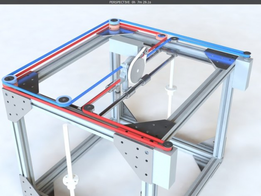
Yep it was close of this one, but with the gantry perpendicular.
Collective intelligence emerges when a group of people work together effectively. Prusa i3 Folger (A lot of the parts are wrong, boring !)
Collective intelligence emerges when a group of people work together effectively. Prusa i3 Folger (A lot of the parts are wrong, boring !)
|
Re: Compact CoreXY Build March 02, 2015 07:53PM |
Registered: 9 years ago Posts: 23 |
I think the two level system has merit, I was just trying to see if I could do a CoreXY while keeping the belts on the same level.
If you like the two level belt system, check out this new thread: Smartrap Core The designer has a good job of keeping everything simple. I've spent some time playing with the JSCAD and really liked what I saw. I think if I didn't already have a new a machine that I would build one.
If you like the two level belt system, check out this new thread: Smartrap Core The designer has a good job of keeping everything simple. I've spent some time playing with the JSCAD and really liked what I saw. I think if I didn't already have a new a machine that I would build one.
|
Re: Compact CoreXY Build June 20, 2015 07:16PM |
Registered: 9 years ago Posts: 53 |
Still liking your design and the idea of the belts on the same level. If the belts are on two levels a torque momment will be introduced at the hot end X-carriage when the entire cross arm starts to accelerate.
Direct rubber on rubber where the belts cross is bound to create some wear. Any updates on the silicone or a separator made out of PLA, Teflon or even a polished steel pin?
Look at how close the Smartrap Core bed is to its rail supports. You had to add quite a bit of arm length and cantilever the bed out to clear the Y slider. How about moving the Z supports and Zscrew to an adjacent side of the cube which allows the bed to be moved closer to the Z rails?
Lots of things can cause Z artifacts. Did you try a dial indicator mounted to the X carriage to look for wiggle and repeatability?
|
Re: Compact CoreXY Build September 28, 2015 09:04PM |
Registered: 9 years ago Posts: 23 |
It has taken me a while to answer this post because it has taken me a while to fix all my z axis issues. But I want to share my results as they may help other makers.
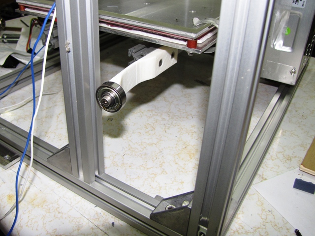
First, in regards to the long arm length on the bed. This does cause some problems, as very small movements at the bearings or z-axis screw are amplified out on the bed. My answer was to pre-load the bearing slightly with an arm on the base of the bed. It's just a printed 608 bearing holder that rides on an extra 2020 extrusion. By bending the arm slightly, it presses the bed to one side.
After trying various changes to my z-axis screw, including moving from a 10mm to 8mm screw, without any results, I finally got around to seriously analyzing the problem. First I printed out some 25mm cubes with single and double walls and did some careful measurements. It was soon evident that my problem was z-ribbing, rather than z-wobble. Each bulge on a side was also matched by a bulge at the same z height on the other side. If the problem had been z-wobble, the side opposite the bulge would be inset. The period of the bulges matched the pitch of the screw.
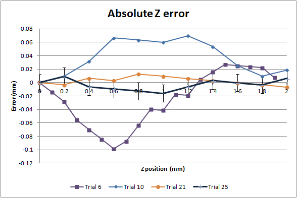
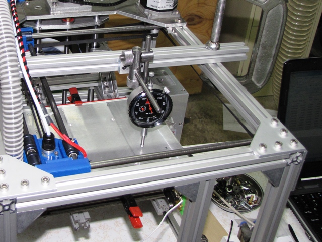
I put a dial indicator on the bed and jogged the bed down 2mm (the screw pitch) stopping every 0.1mm and taking a reading. When plotted the height variation was obvious. I had an error of about 0.12mm peak to peak. That's a lot when using layer heights of 0.25mm.
After a lot of reading, it seemed that there were 3 main causes of z-ribbing. The most common cause was rounding error when using a imperial screw with metric heights. Since I'm running a metric lead screw and using layer heights that were divisible by full steps, this seemed very unlikely.
The second cause was bed temperature variation, normally due to bang-bang control. I'm using PID control on the bed, so I didn't think this was my problem. I watched the bed temperature read out on Repetier Host and it varied less than +- 0.5 degrees C. I also put a dial indicator on the bed and it didn't move.
The last common cause I found was a misaligned axis and screw. Since I was using the lead screw nut holder to also tie the sides of the bed support together, I thought this might be part of the problem. So first I put a piece of 2020 extrusion between the bed sides. That allowed my to take my z lead screw nut holder and move it around to get the best alignment. As a result, I eliminated about 1/2 of the error (trial 10 on the chart).
To eliminate the rest of the error I tried many different alignments of the lead nut holder. I tilted it, moved it left and right, in and out, all for no real change in the error. I also tried different bearing arrangements: thrust bearing only at the top, 608 bearing at the top, and 608 bearings top and bottom. Nothing improved the error.
Finally after reading about a lot of the different z-screw connectors that fixed other z-ribbing issues, I changed out the coupler. I was running a spiral cut aluminum coupler and I put a rigid coupler made from brass in its place. That eliminated most of the rest of the error (trial 21 on the chart). My dial indicator has graduations of 0.001 inches (+-0.0127mm) so when you add the error bars to the chart, almost every point is within the measurement error.
Even with this small error, z-ribbing was still evident in the printed parts. I tried some other adjustments, but nothing really improved the prints. Plus the error was too small to really track down with the dial indicator that I was using.
At this point I suspect the plastic nut was causing my problems. Maybe the initial running of the screw in the misaligned position caused the nut to wear unevenly. I considered buying another replacement lead screw and/or nut, but I decided I wanted to stop messing with the problem regardless of the cost. So I ordered a stepper motor with an integrated lead screw from Pololu (https://www.pololu.com/product/2268) with a brass nut rather than a plastic one. Installation of the new stepper motor and lead screw eliminated all of my z-ribbing.
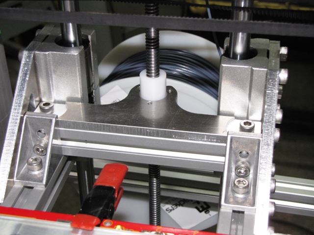
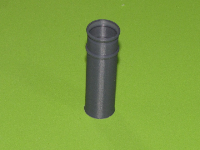
I still had some z artifacts, but now they were no longer the same spacing at the lead screw pitch. I had the filament twist out my extruder a couple of times as it got to the tightly coiled part at the end of the reel, so I added a filament guide made using 4" of nylon tubing. It not only eliminated the tendency for the filament to twist out, it also eliminated most of my remaining z artifacts. I guess the filament was wandering side-to-side and causing a variation in the extruded plastic. As a bonus, the filament is much easier to load now.
The printer has in excess of 150 hours on it now. The crossed belts are still working fine, with little wear visible other than a slight shininess to the belts.
Edited 3 time(s). Last edit at 09/29/2015 08:13PM by rcengr.
First, in regards to the long arm length on the bed. This does cause some problems, as very small movements at the bearings or z-axis screw are amplified out on the bed. My answer was to pre-load the bearing slightly with an arm on the base of the bed. It's just a printed 608 bearing holder that rides on an extra 2020 extrusion. By bending the arm slightly, it presses the bed to one side.
After trying various changes to my z-axis screw, including moving from a 10mm to 8mm screw, without any results, I finally got around to seriously analyzing the problem. First I printed out some 25mm cubes with single and double walls and did some careful measurements. It was soon evident that my problem was z-ribbing, rather than z-wobble. Each bulge on a side was also matched by a bulge at the same z height on the other side. If the problem had been z-wobble, the side opposite the bulge would be inset. The period of the bulges matched the pitch of the screw.
I put a dial indicator on the bed and jogged the bed down 2mm (the screw pitch) stopping every 0.1mm and taking a reading. When plotted the height variation was obvious. I had an error of about 0.12mm peak to peak. That's a lot when using layer heights of 0.25mm.
After a lot of reading, it seemed that there were 3 main causes of z-ribbing. The most common cause was rounding error when using a imperial screw with metric heights. Since I'm running a metric lead screw and using layer heights that were divisible by full steps, this seemed very unlikely.
The second cause was bed temperature variation, normally due to bang-bang control. I'm using PID control on the bed, so I didn't think this was my problem. I watched the bed temperature read out on Repetier Host and it varied less than +- 0.5 degrees C. I also put a dial indicator on the bed and it didn't move.
The last common cause I found was a misaligned axis and screw. Since I was using the lead screw nut holder to also tie the sides of the bed support together, I thought this might be part of the problem. So first I put a piece of 2020 extrusion between the bed sides. That allowed my to take my z lead screw nut holder and move it around to get the best alignment. As a result, I eliminated about 1/2 of the error (trial 10 on the chart).
To eliminate the rest of the error I tried many different alignments of the lead nut holder. I tilted it, moved it left and right, in and out, all for no real change in the error. I also tried different bearing arrangements: thrust bearing only at the top, 608 bearing at the top, and 608 bearings top and bottom. Nothing improved the error.
Finally after reading about a lot of the different z-screw connectors that fixed other z-ribbing issues, I changed out the coupler. I was running a spiral cut aluminum coupler and I put a rigid coupler made from brass in its place. That eliminated most of the rest of the error (trial 21 on the chart). My dial indicator has graduations of 0.001 inches (+-0.0127mm) so when you add the error bars to the chart, almost every point is within the measurement error.
Even with this small error, z-ribbing was still evident in the printed parts. I tried some other adjustments, but nothing really improved the prints. Plus the error was too small to really track down with the dial indicator that I was using.
At this point I suspect the plastic nut was causing my problems. Maybe the initial running of the screw in the misaligned position caused the nut to wear unevenly. I considered buying another replacement lead screw and/or nut, but I decided I wanted to stop messing with the problem regardless of the cost. So I ordered a stepper motor with an integrated lead screw from Pololu (https://www.pololu.com/product/2268) with a brass nut rather than a plastic one. Installation of the new stepper motor and lead screw eliminated all of my z-ribbing.
I still had some z artifacts, but now they were no longer the same spacing at the lead screw pitch. I had the filament twist out my extruder a couple of times as it got to the tightly coiled part at the end of the reel, so I added a filament guide made using 4" of nylon tubing. It not only eliminated the tendency for the filament to twist out, it also eliminated most of my remaining z artifacts. I guess the filament was wandering side-to-side and causing a variation in the extruded plastic. As a bonus, the filament is much easier to load now.
The printer has in excess of 150 hours on it now. The crossed belts are still working fine, with little wear visible other than a slight shininess to the belts.
Edited 3 time(s). Last edit at 09/29/2015 08:13PM by rcengr.
|
Re: Compact CoreXY Build September 29, 2015 08:18AM |
Registered: 9 years ago Posts: 346 |
Hey Rcengr,
Your post is very interesting. It is rare that somebody goes into such depth to investigate problems.
I would like to know more about how your parts looked throughout the process. It will help me in the future if I come across something like it.
Any chance you can take some pictures of your older parts? Especially I am interested how it looked before you fixed the filament issue.
|
Re: Compact CoreXY Build September 29, 2015 08:11PM |
Registered: 9 years ago Posts: 23 |
As an engineer I always want more information, hence all the research. 
The previous version of the z-axis you can find on the first page of this thread, look about 2/3 the way down.
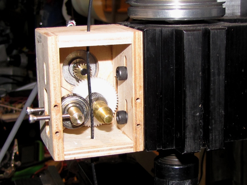
I've attached a picture of my extruder. It's an original design, made from materials on-hand and with my CNC mill. It was only supposed to last until I got the printer going and then I was going to print a more common design. However, it has worked so well that I haven't been motivated to change it.
As you can see from the first picture, there's a hole at the top and bottom to guide the filament but nothing else until the drive gear.
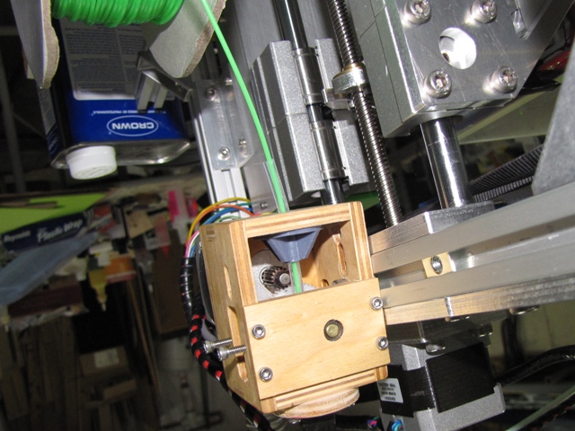
The second picture shows the new grey filament support. It's printing right now so I can't take the shaft support off for a better picture. The nylon feed tube extends right up to the drive gear. On the other side, the Bowden tube extends down to the drive gear, so the filament is constrained over almost it's entire path through the extruder.
Edited 1 time(s). Last edit at 09/29/2015 08:17PM by rcengr.
The previous version of the z-axis you can find on the first page of this thread, look about 2/3 the way down.
I've attached a picture of my extruder. It's an original design, made from materials on-hand and with my CNC mill. It was only supposed to last until I got the printer going and then I was going to print a more common design. However, it has worked so well that I haven't been motivated to change it.
As you can see from the first picture, there's a hole at the top and bottom to guide the filament but nothing else until the drive gear.
The second picture shows the new grey filament support. It's printing right now so I can't take the shaft support off for a better picture. The nylon feed tube extends right up to the drive gear. On the other side, the Bowden tube extends down to the drive gear, so the filament is constrained over almost it's entire path through the extruder.
Edited 1 time(s). Last edit at 09/29/2015 08:17PM by rcengr.
|
Re: Compact CoreXY Build December 16, 2015 04:46AM |
Registered: 13 years ago Posts: 301 |
When I saw the drawing of your CoreXY respin I instantly knew it was the belt path I wanted to try. [plus.google.com]
|
Re: Compact CoreXY Build December 16, 2015 04:57AM |
Registered: 9 years ago Posts: 3,385 |
|
Re: Compact CoreXY Build December 16, 2015 02:48PM |
Registered: 9 years ago Posts: 23 |
Quote
Skimmy
And get new belts every 3 months?
Not quite. I've been using my machine for over a year and there is still no visible wear on the belts. I'll have to look at my logs for the latest number, but last time I checked I had over 200 hours of print time. I haven't even needed to re-tension the belts.
|
Re: Compact CoreXY Build December 16, 2015 03:08PM |
Registered: 9 years ago Posts: 23 |
Quote
billyzelsnack
When I saw the drawing of your CoreXY respin I instantly knew it was the belt path I wanted to try. [plus.google.com]
I like your machine.
|
Re: Compact CoreXY Build December 18, 2015 12:33PM |
Registered: 12 years ago Posts: 45 |
|
Re: Compact CoreXY Build December 19, 2015 10:00AM |
Registered: 9 years ago Posts: 23 |

Sorry, only registered users may post in this forum.