Would this work?
Posted by Dave_robinson_022
|
Would this work? April 23, 2015 09:43PM |
Registered: 9 years ago Posts: 25 |
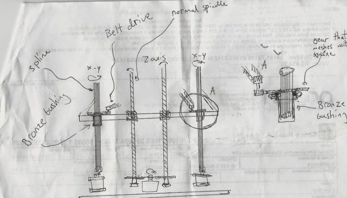
I was having a think about CoreXY solutions and had a look at the X3D XS CoreXY which looked good but still has Z axis moving. I was wondering if I removed the stepper motors from the gantry with the CoreXY and had this sliding on rods (probably unconstrained at the top end) if I could not extend the idea to the Z axis as well. Obviously the rear two 'rods' would need to be able to turn the spindles on the gantry to be able to control the X and Y Axis so I would suggest a Triangular rod. This would then have to allow Z axis movement so I came up with a quick bearing support. I would implenment the gantry movement on the underside and alow gravity to hold them in place. As the gantry is suspended, unless it drops at a rate to allow the spindles to move up then this shouldn't be an issue.
What do you guys think? As I said, it was a quick lunchtime musing and I haven't worked out finer details; that is why the concept is hand drawn.
Cheers,
Dave
What do you guys think? As I said, it was a quick lunchtime musing and I haven't worked out finer details; that is why the concept is hand drawn.
Cheers,
Dave
|
Re: Would this work? April 24, 2015 10:22AM |
Registered: 9 years ago Posts: 346 |
First off, I don't understand the red and blue lines in the lower left corner. It looks like you want the X-Y belts to also run in the Z axis - But at the same time it is my understanding that you want two Z axis rods to double as linear guides and transfer rotation to the X-Y gantry?
Assuming you want to make a normal system but with the steppers transferring through these linear rods -
I don't think it will work.
Look at your rectangular rod which is supposed to turn and transfer rotational movement to the outer cape. What is preventing your rectangular rod from just rotating? The friction force from the rod turning and pushing the steel ball to one side and thus creating a lock will maybe be enough but I am not so sure. It will anyway require some steep tolerances to avoid that you over time wear down the balls - Especially if you then afterwards have movement in the z direction and the ball does not start to turn - That will make a flat point on the ball.
The idea certainly has merits. You could use a standard spline and grease that heavily and let a bronze bushing run on the outer diameter. It will create some more friction for the Z-axis to overcome and you will maybe end up needing two spindles drive to avoid skewing and thus locking - But should work.
I made a quick sketch:
A spline intermeshing looks like this:
It is important to understand that when the Z-axis moves up and down this connection will have to slide by the grease / lubrication that would need to be applied. For this reason it could be necessary to encapsulate the entire thing to avoid plastic, hairspray and what not to stick to the spline.
Edited 1 time(s). Last edit at 04/24/2015 10:30AM by LarsK.
|
Re: Would this work? April 24, 2015 10:41AM |
Registered: 9 years ago Posts: 346 |
|
Re: Would this work? April 25, 2015 06:23PM |
Registered: 9 years ago Posts: 25 |
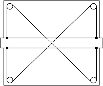
Apologies for the lack of clarity on my drawings. You are correct that I want to transfer the rotary motion through the rear supporting rods and your spline idea is what I was trying to get at. The second diagram is a little confusing; basically I was trying to implement a smaller idea:
to the Z-axis. This may be over engineering the solution, but I notice that most Z-Axis ate fixed and moved along the rear plane... I thought that if I could balance the control by trying to apply the above diagram to either side then this may help with levelling? The other option i considered was using the exact plan above mired on the left and right side, driven by an axel to operate both simultaneously?
What I am trying to achieve overall is to keep the gantry as light as possible as in a delta style by removing the stepper motors from them but keeping the control as direct as possible and removing the complications of delta math from the situation. Is there anything else like this?
|
Re: Would this work? April 27, 2015 08:56AM |
Registered: 10 years ago Posts: 553 |
That design would need to be driven by 2 motors the way it is drawn. That wouldn't get rid of a level problems. It would be the same as using 2 lead screws on opposite ends of the bed; if one skips a step or binds slightly, your bed will become un-level.
If you are trying to keep the gantry as light as possible, why not just use a corexy system? The X and Y motors are static and the gantry can be made pretty light with the right design. Making the Z axis super light is kinda a moot point, be cause doesn't make large move while printing. As long as the z axis is stiff and the motor is strong enough, it should be good.
greghoge.com
HUGE 3D PRINTER PARTS SALE!!!
|
Re: Would this work? April 28, 2015 07:06AM |
Registered: 9 years ago Posts: 25 |
Quote
gmh39
That design would need to be driven by 2 motors the way it is drawn. That wouldn't get rid of a level problems. It would be the same as using 2 lead screws on opposite ends of the bed; if one skips a step or binds slightly, your bed will become un-level.
If you are trying to keep the gantry as light as possible, why not just use a corexy system? The X and Y motors are static and the gantry can be made pretty light with the right design. Making the Z axis super light is kinda a moot point, be cause doesn't make large move while printing. As long as the z axis is stiff and the motor is strong enough, it should be good.
2 stepper motors still weigh quite a bit. The idea was to achieve the advantages of a delta design with lightness and speed of effector movement without the delta math.
|
Re: Would this work? April 28, 2015 07:31AM |
Registered: 10 years ago Posts: 14,672 |
Quote
Dave_robinson_022
2 stepper motors still weigh quite a bit. The idea was to achieve the advantages of a delta design with lightness and speed of effector movement without the delta math.
While it would be nice to see a CoreXY design that is as fast, stable and mechanically simple (e.g. fixed bed) as a delta - or simpler and even more stable, delta math is a solved problem. Segmentation of long moves into lots of short moves is no longer necessary, using modern electronics and firmware. I think there are still issues with some delta designs, but math isn't one of them.
Edited 1 time(s). Last edit at 04/28/2015 07:32AM by dc42.
Large delta printer [miscsolutions.wordpress.com], E3D tool changer, Robotdigg SCARA printer, Crane Quad and Ormerod
Disclosure: I design Duet electronics and work on RepRapFirmware, [duet3d.com].
|
Re: Would this work? April 28, 2015 10:36AM |
Registered: 10 years ago Posts: 553 |
Quote
Dave_robinson_022
Quote
gmh39
That design would need to be driven by 2 motors the way it is drawn. That wouldn't get rid of a level problems. It would be the same as using 2 lead screws on opposite ends of the bed; if one skips a step or binds slightly, your bed will become un-level.
If you are trying to keep the gantry as light as possible, why not just use a corexy system? The X and Y motors are static and the gantry can be made pretty light with the right design. Making the Z axis super light is kinda a moot point, be cause doesn't make large move while printing. As long as the z axis is stiff and the motor is strong enough, it should be good.
2 stepper motors still weigh quite a bit. The idea was to achieve the advantages of a delta design with lightness and speed of effector movement without the delta math.
If you are trying to move the gantry in the X, Y and Z directions, a spline (as mentioned above) would be your best bet. You could have the motors fixed and drive the spline remotely for the X and Y, then use a leadscrew to drive the Z axis. The gantry can move smoothly along the splines in teh Z direction, but the X and Y motors can turn the splines to drive the X and Y axis'. That'd be pretty sweet!
greghoge.com
HUGE 3D PRINTER PARTS SALE!!!
|
Re: Would this work? April 28, 2015 10:42AM |
Registered: 9 years ago Posts: 346 |
Hello Dave,
First off, I agree with the others. The concept with two motors will complicated and the gains rather limited. If you want to move the gantry then sticking to the leadscrews moved by one motor is better. But for the gantry movement motors; You should remember that the motors are not really that heavy and the Z axis do not move that often. Mass reduction versus loss of stability is not black and white.
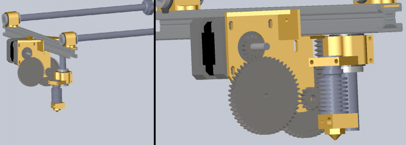
I wanted to show you something that I have been working on which is sort of related. Here I am moving just the nozzle on the carriage. This means I have to move this stepper motor all the time and thus I will lose speed. But it is more compact then having a moving bed (and in some aspects simpler). In this setup it allows me to print to a max 50mm height but I have found the vast majority of my parts to be in that range. But it is still in early design phase. My current main issue is resolution on the z axis. When driving without gears (directly on the stepper) it will move the nozzle too much.
This was particularly bad on my first design and in this design I would also have the problem that the movement would not be entirely linear and I would maybe need software for that.
This is the current design:
Sorry, only registered users may post in this forum.


