"Project Locus" - *gasp* My Plastic Frame - CoreXY Build Thread
Posted by redhatman
|
"Project Locus" - *gasp* My Plastic Frame - CoreXY Build Thread May 09, 2015 11:46PM |
Registered: 9 years ago Posts: 57 |
Hello Fellow RepRappers,
After some brainstorming with other members and deciding which route to take with my new printer build, I decided to go the CoreXY route. ( [forums.reprap.org] )
With a target goal of a cubic foot build area, yet a low budget of roughly $500, compromises had to be made wherever possible. The main one budget cut was substituting the standard 20x20 Aluminum Extrusions. After doing some calculations and estimating the cost of aluminum extrusions/brackets, I was well over where I wanted to be. From what I remember; aluminum extrusions alone would run ~$100, as well as a minimum of 24 right angle brackets ($2-3 each). This doesn't include any other small brackets which would be needed other than simply making a cube of the desired size.
Here's where the controversy begins... Instead of using the Aluminum extrusions, I wanted to entertain the idea of creating similar extrusions from PLA using my Prusa i2. After some prototype testing, I decided to begin ordering parts, as well as a few spools of filament to get printing. I figured even if I used 6 spools of filament, that would only cost me $120, and combined with CAD skills, I could make the entire printer.
Now, onto the build. Being I decided to start this thread at 10pm on a Saturday night, I'll likely only start the thread, and finish uploading pictures later.
Edited 1 time(s). Last edit at 05/09/2015 11:47PM by redhatman.
- "Project Locus" - Mostly all printed parts, Corexy, Bowden Setup, 12x12 heatbed, ~1 cubic foot build volume
- SeeMeCNC Rostock Max V2
|
Re: "Project Locus" - *gasp* My Plastic Frame - CoreXY Build Thread May 11, 2015 08:05PM |
Registered: 10 years ago Posts: 553 |
So you're trying to save ~$30 for in the hope that printed extrusion will hold up? I'm sure there are much better ways to accomplish your goal.
Are you set on designing the printer yourself? If not, check out the Smart Core. It's a CoreXY designed by the guys that did the Smart Rap printer.
If you are, I'm 100% positive you can get enough to make the frame (a basic cube) for less than $100 from OpenBuilds (500mm 2020 extrusion, corner cube brackets, and 25mm screws).
Either way, I'm still interested in seeing how this turns out.
greghoge.com
HUGE 3D PRINTER PARTS SALE!!!
|
Re: "Project Locus" - *gasp* My Plastic Frame - CoreXY Build Thread May 13, 2015 12:50AM |
Registered: 9 years ago Posts: 57 |
Quote
gmh39
So you're trying to save ~$30 for in the hope that printed extrusion will hold up? I'm sure there are much better ways to accomplish your goal.
Are you set on designing the printer yourself? If not, check out the Smart Core. It's a CoreXY designed by the guys that did the Smart Rap printer.
If you are, I'm 100% positive you can get enough to make the frame (a basic cube) for less than $100 from OpenBuilds (500mm 2020 extrusion, corner cube brackets, and 25mm screws).
Either way, I'm still interested in seeing how this turns out.
To be honest, I hadn't heard of openbuilds when I was shopping around, the cheapest I found was either through dealers on eBay or Misumi. Regardless, this is more of a proof of concept, paving a path of sorts, because I believe it could be done. Don't get me wrong, I understand aluminum extrusions are likely the best option, however as I mentioned, budget was the main factor.
Yes, I am set on designing the entire printer myself, minus basic belt path. Leaving the "dreaded crossover" for me to figure out.
I'm glad to hear there's some interest in this, and I appreciate the critiques, honestly. The printer is operational now, I just have to post the pictures and do some write-ups.
- "Project Locus" - Mostly all printed parts, Corexy, Bowden Setup, 12x12 heatbed, ~1 cubic foot build volume
- SeeMeCNC Rostock Max V2
|
Re: "Project Locus" - *gasp* My Plastic Frame - CoreXY Build Thread May 13, 2015 07:47AM |
Registered: 9 years ago Posts: 346 |
Hello Redhatman,
MichelleF over at the laser forum part posted about her Kickstarter campaign; [www.kickstarter.com]
They do what you say, use plastic printed parts for the frame (but only XY, no Z because it is a laser).
Also you may want to have a look at SlotBot ( [www.thingiverse.com] ) and Uconduit ( [www.thingiverse.com] ). Both these printers are using other frames then extruded alu.
Finally, when talking about extruded profiles I really think that the nuts must be taken into account. With my vendor here in Brazil I pay:
1m 20x20 - 5 USD
1 nut for 20x20 - 0.5 USD
90 deg angle - 2.15 USD
I just checked and it looks like Openbuilds charges roughly the same.
So If I want to use angles on all sides and 2 bolts/nuts then the costs really build up.
|
Re: "Project Locus" - *gasp* My Plastic Frame - CoreXY Build Thread May 14, 2015 11:48PM |
Registered: 9 years ago Posts: 57 |
LarsK, those are some cool links you provided! Thanks!
I meant to get all of the pictures I have posted last night, however I was trying to resize them to comply with the forum limits and after using 2 different programs on 100 photos I had no desirable results worth dealing with. Currently uploading to photobucket as we speak, so we'll just have to go that route.
- "Project Locus" - Mostly all printed parts, Corexy, Bowden Setup, 12x12 heatbed, ~1 cubic foot build volume
- SeeMeCNC Rostock Max V2
|
Re: "Project Locus" - *gasp* My Plastic Frame - CoreXY Build Thread May 15, 2015 12:53AM |
Registered: 9 years ago Posts: 57 |
Okay... At last...
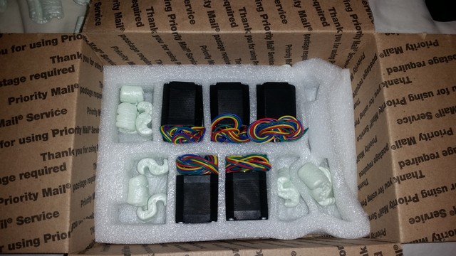
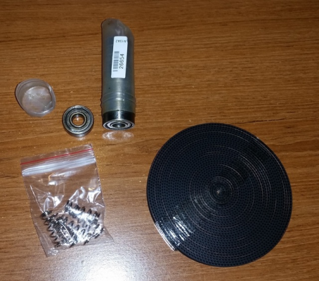
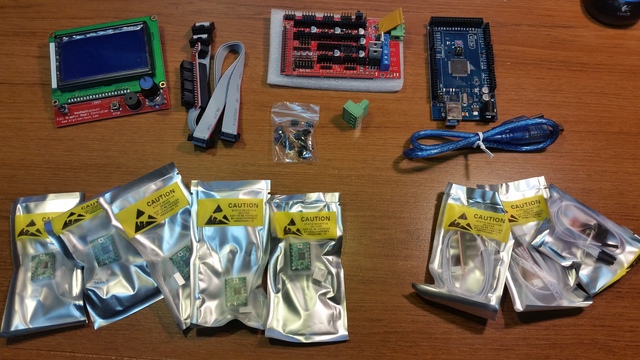
Once doing lots of brainstorming and sketching during class (whoops), I decided I wanted to use common parts, and build the printer around those. Some of which, but not limited to (I'm sure I'll forget some things) are:
-Nema 17 Motors
-E3D Style Hot End
-Bowden Setup
-CoreXY
-Ramps 1.4 / Mega
-Lots of 608 Bearings
-GT2 Belts
-8mm Smooth Rod
-8mm x 1.25 Threaded Rod (WAY cheaper than leadscrew)
-LCD Screen w/SD so I don't need a dedicated computer
-Computer PSU adapted for the 12v sources
-12x12" Heatbed
-40mm Fans
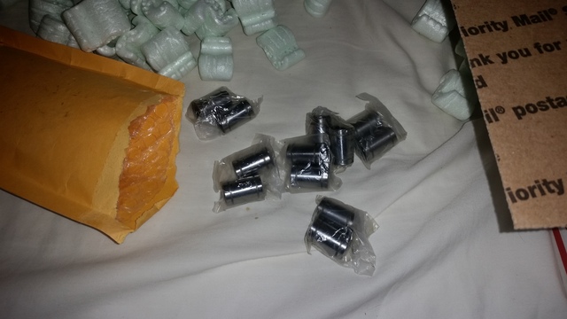
-LM8UU Bearings
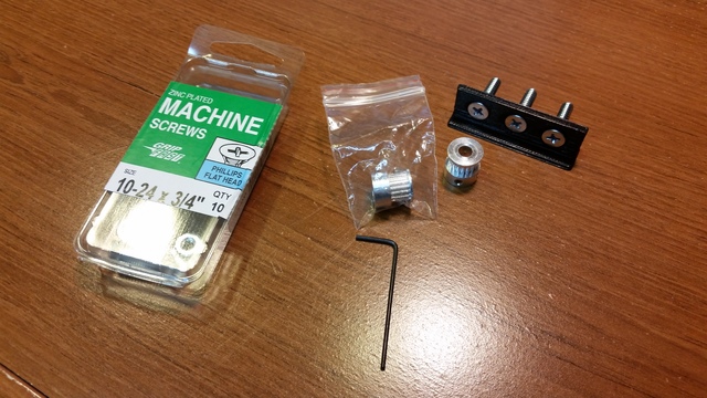
-Cheapest suitable fasteners available at hardware store
-Threaded Rod from hardware store; 5/16", not a single store around me sells 8mm rod.
With that being said, I began ordering parts before actually starting the CAD work. I would continue to do CAD as parts arrived, taking dimensions, and building around what I have.
Super awesome 12"x12" Heatbed from Jim at 3Dheatbeds (eBay name). I highly recommend their beds, customer service is nothing short of outstanding.
IMG]http://i7.photobucket.com/albums/y271/redhatman/Project%20Locus/20150204_140201_zpsk360vowf.jpg[/IMG]
Being the heatbed requires 20-24A during startup from initial temp, I needed to run a relay as well as an adequate power supply (hint: this proves to not be adequate, regardless of the 34A rating).
- "Project Locus" - Mostly all printed parts, Corexy, Bowden Setup, 12x12 heatbed, ~1 cubic foot build volume
- SeeMeCNC Rostock Max V2
|
Re: "Project Locus" - *gasp* My Plastic Frame - CoreXY Build Thread May 15, 2015 12:56AM |
Registered: 9 years ago Posts: 57 |
- "Project Locus" - Mostly all printed parts, Corexy, Bowden Setup, 12x12 heatbed, ~1 cubic foot build volume
- SeeMeCNC Rostock Max V2
|
Re: "Project Locus" - *gasp* My Plastic Frame - CoreXY Build Thread May 15, 2015 01:11AM |
Registered: 9 years ago Posts: 57 |
Time to do some experimentation and designing!
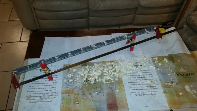
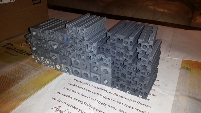
Extrusions and corners would be first, this would be the backbone of the printer. In an effort to conserve filament for the primarily plastic printer, I used expanding foam on nearly all parts. The parts were printed using anywhere from 0-20% infill, depending on where their function. I avoided using foam in places which may be exposed to heat.
The frame structure sides are made from 6 extrusions per side, with 1/4" threaded rod running through them. In a combination with the foam packed extrusions, they would also be held together in tension, with super glue bonding the mate surfaces when installed. Cleaning the foam was easy, but time consuming. Being a college student, I have a few roommates who were willing to help if I gave them some beer to pass the time while they aided in cleaning up the parts.
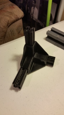
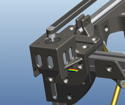
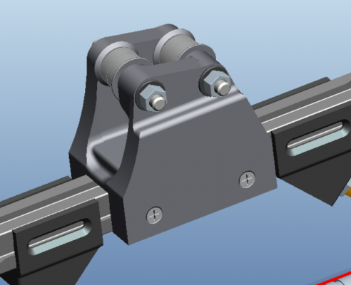
First rev of corners, knowing changes would be made, these parts were printed at a smaller scale, and only used to help get a feel for the general design.
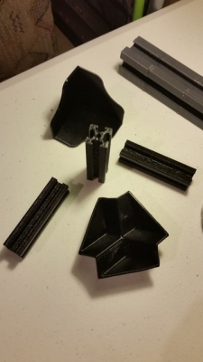
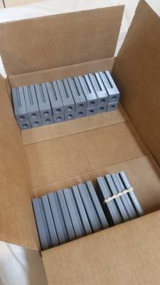
Original thought of how I would do the end pieces of each frame side. Unfortunately, I ended up changing my mind later and had 24ish of these printed at full scale (grey pla). The reason I didn't like these was because when tightening the rods in compression, it worked, but I couldn't get the rods to the desired compression before I was afraid of twisting further and breaking the extrusions from the mating surface friction between parts.
- "Project Locus" - Mostly all printed parts, Corexy, Bowden Setup, 12x12 heatbed, ~1 cubic foot build volume
- SeeMeCNC Rostock Max V2
|
Re: "Project Locus" - *gasp* My Plastic Frame - CoreXY Build Thread May 15, 2015 01:17AM |
Registered: 9 years ago Posts: 57 |
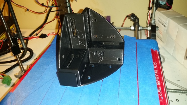
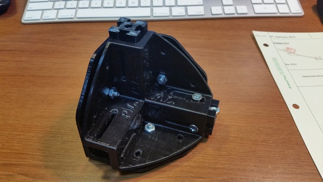
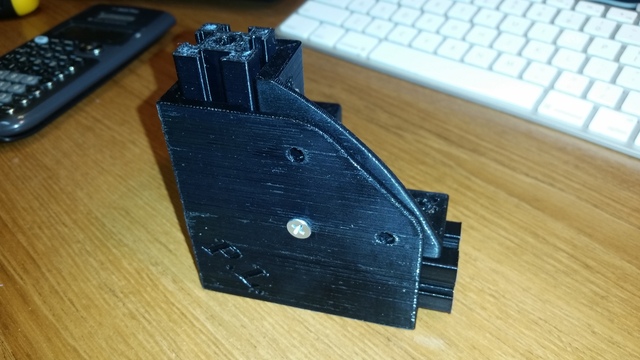
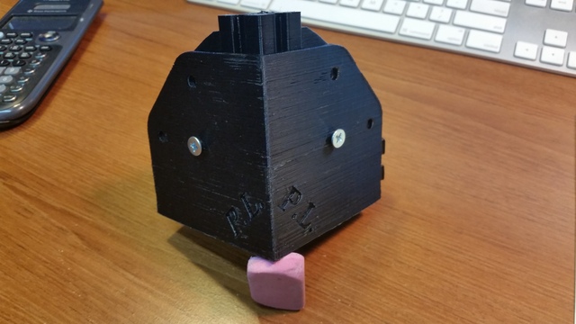
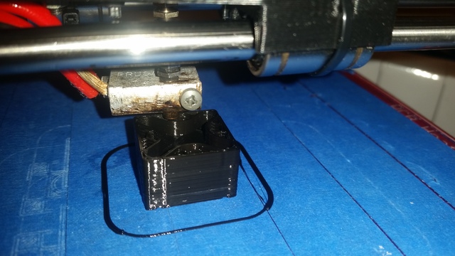
Corner pieces, almost final rev. I ended up printing 4 of these, and for the last 4, I added chamfers to countersink the bolt heads to the CAD file, leaving the first 4 brackets to chamfer by hand (drill bit). The reason I was always printing parts is because I had a time limit of 3 months to finish this project (while I had full access and time to use the Prusa). Considering these corner brackets were each at least a few hours to print, I wasted as little time as possible and kept the Prusa i2 running whenever I could.
The "P.L." is my initials. The name "Project Locus" didn't come until the end of the build.
Edited 1 time(s). Last edit at 05/15/2015 01:19AM by redhatman.
- "Project Locus" - Mostly all printed parts, Corexy, Bowden Setup, 12x12 heatbed, ~1 cubic foot build volume
- SeeMeCNC Rostock Max V2
The "P.L." is my initials. The name "Project Locus" didn't come until the end of the build.
Edited 1 time(s). Last edit at 05/15/2015 01:19AM by redhatman.
- "Project Locus" - Mostly all printed parts, Corexy, Bowden Setup, 12x12 heatbed, ~1 cubic foot build volume
- SeeMeCNC Rostock Max V2
|
Re: "Project Locus" - *gasp* My Plastic Frame - CoreXY Build Thread May 15, 2015 02:53AM |
Registered: 9 years ago Posts: 57 |
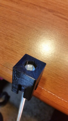
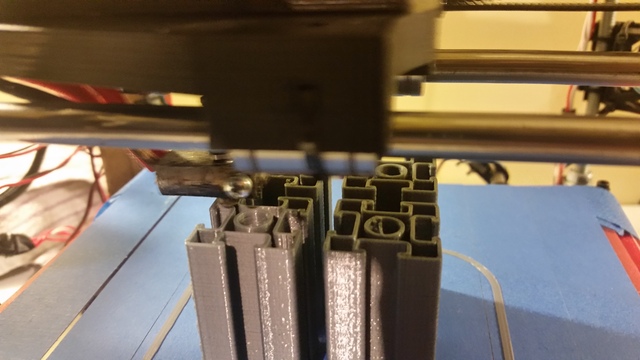
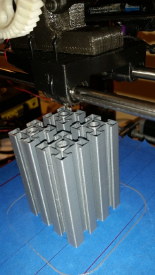
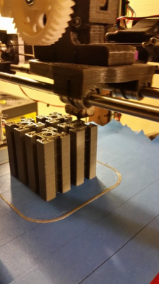
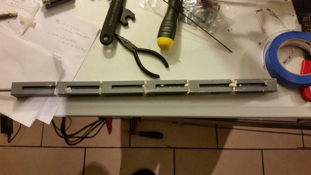
Onto the extrusions, note that these are hollow, most of the frame components ended up being foam filled and 15-20% infill as well.
2 cans for $5 at Menards
Since this stuff is such a mess to work with, and I was injecting all of these at 4 points each, I decided it would be beneficial to make some sort of divider tool to help distribute the foam vs. filling 4 holes each. I clamped them end to end so the foam would fill in as dense as possible before eventually coming out wherever it could.
The extrusions with the side chunk missing are for inserting nuts to mount components along the frame.
Edited 1 time(s). Last edit at 05/15/2015 02:54AM by redhatman.
- "Project Locus" - Mostly all printed parts, Corexy, Bowden Setup, 12x12 heatbed, ~1 cubic foot build volume
- SeeMeCNC Rostock Max V2
|
Re: "Project Locus" - *gasp* My Plastic Frame - CoreXY Build Thread May 15, 2015 03:34PM |
Registered: 10 years ago Posts: 105 |
|
Re: "Project Locus" - *gasp* My Plastic Frame - CoreXY Build Thread May 17, 2015 08:29PM |
Registered: 9 years ago Posts: 57 |
Quote
runninfarmer
Cool idea with the foam filled extrusions. I'm interested to see how well they perform!
Thanks! Again, this was in an effort to conserve filament as well as add rigidity at a low cost. So far they seem to be working pretty well!
- "Project Locus" - Mostly all printed parts, Corexy, Bowden Setup, 12x12 heatbed, ~1 cubic foot build volume
- SeeMeCNC Rostock Max V2
|
Re: "Project Locus" - *gasp* My Plastic Frame - CoreXY Build Thread May 17, 2015 08:37PM |
Registered: 9 years ago Posts: 57 |
Now onto the design. As I said, this was done over the course of roughly 2-3 months, and the printer was still being designed (and is never really complete) while parts were being printed as assembled. A few parts went through a couple of revisions, but I more so did stuff component by component, and designed around what I had available for hardware and the current design state/availability to mount parts.
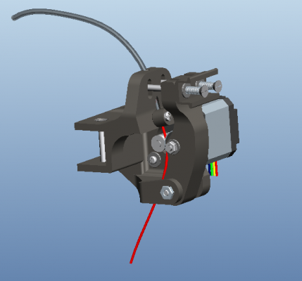
Bowden Extruder Setup, to be mounted on the rear/top of the frame.
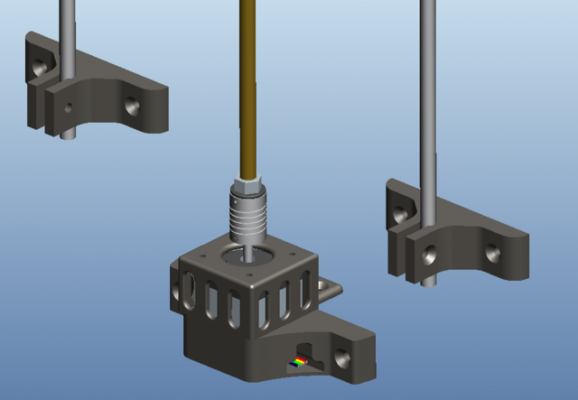
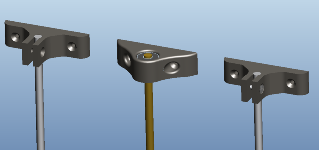
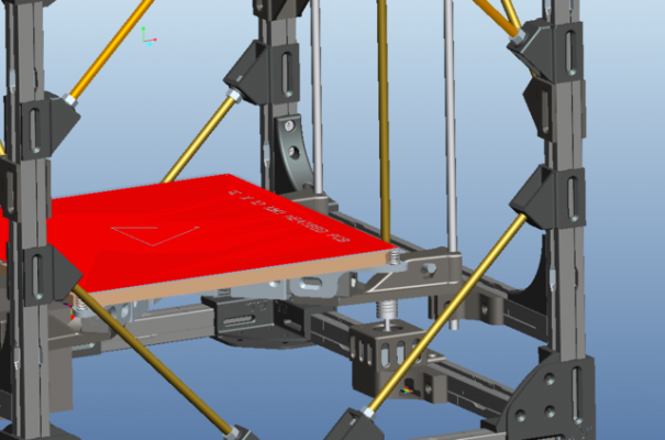
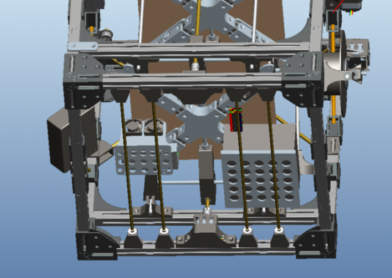
Z Motor Bucket/ Z axis components
- "Project Locus" - Mostly all printed parts, Corexy, Bowden Setup, 12x12 heatbed, ~1 cubic foot build volume
- SeeMeCNC Rostock Max V2
Bowden Extruder Setup, to be mounted on the rear/top of the frame.
Z Motor Bucket/ Z axis components
- "Project Locus" - Mostly all printed parts, Corexy, Bowden Setup, 12x12 heatbed, ~1 cubic foot build volume
- SeeMeCNC Rostock Max V2
|
Re: "Project Locus" - *gasp* My Plastic Frame - CoreXY Build Thread May 17, 2015 08:41PM |
Registered: 9 years ago Posts: 57 |
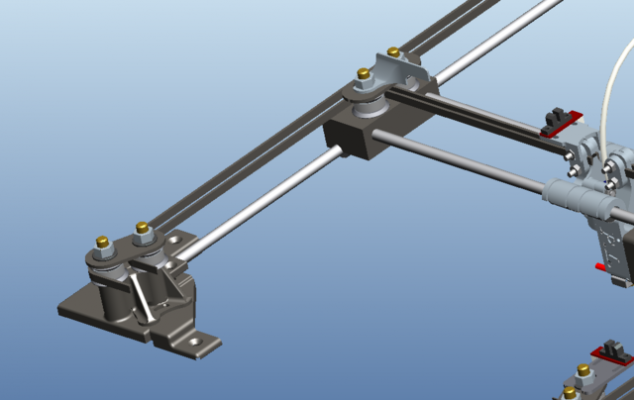
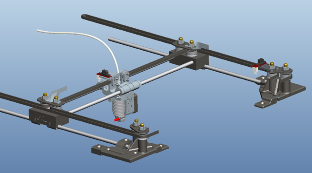
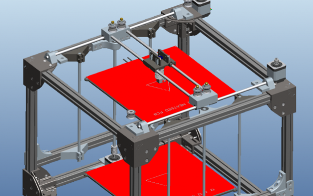
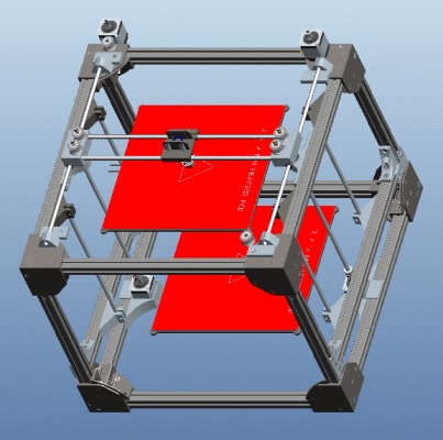
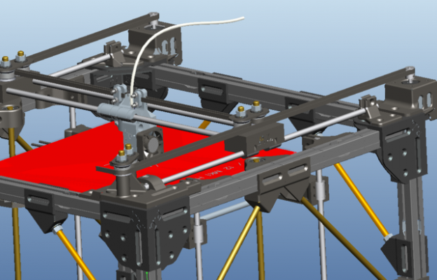
Top XY Assembly
- "Project Locus" - Mostly all printed parts, Corexy, Bowden Setup, 12x12 heatbed, ~1 cubic foot build volume
- SeeMeCNC Rostock Max V2
|
Re: "Project Locus" - *gasp* My Plastic Frame - CoreXY Build Thread May 17, 2015 08:47PM |
Registered: 9 years ago Posts: 57 |
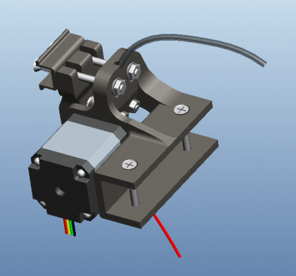
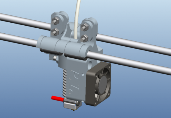
Hot End Assembly. The Carriage is a two-part design, which splits at the cross section of the Hot End.
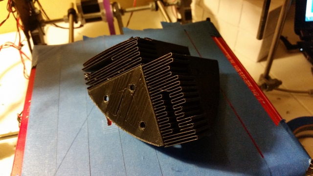
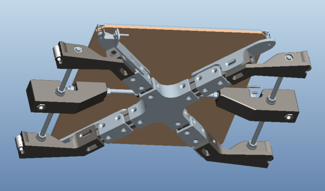
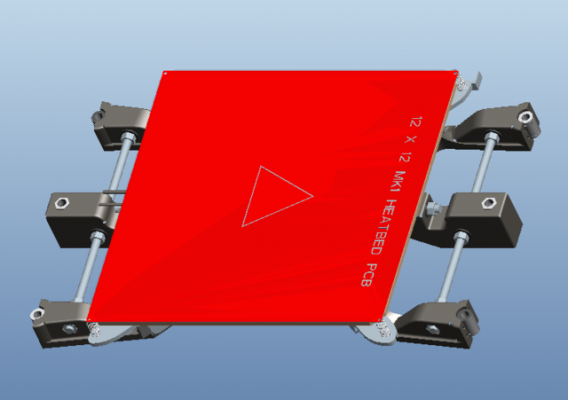
Now onto the bed. I had a few ideas for how I wanted to do the bed, most followed the standard idea of using a sheet of wood/polycarbonate/aluminum, cut to shape. However, after pricing those materials, I couldn't help but think how much I would rather use the 24 end pieces I had made before, which were for now rendered useless. After some brainstorming, sketching, and some playing around, I managed to get everything mounted that needed to be there. Plus, I think it looks kinda cool.
Edited 1 time(s). Last edit at 05/17/2015 08:49PM by redhatman.
- "Project Locus" - Mostly all printed parts, Corexy, Bowden Setup, 12x12 heatbed, ~1 cubic foot build volume
- SeeMeCNC Rostock Max V2
|
Re: "Project Locus" - *gasp* My Plastic Frame - CoreXY Build Thread May 17, 2015 08:51PM |
Registered: 9 years ago Posts: 57 |
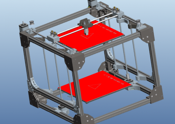
It's kinda starting to look like a printer at this point!
- "Project Locus" - Mostly all printed parts, Corexy, Bowden Setup, 12x12 heatbed, ~1 cubic foot build volume
- SeeMeCNC Rostock Max V2
- "Project Locus" - Mostly all printed parts, Corexy, Bowden Setup, 12x12 heatbed, ~1 cubic foot build volume
- SeeMeCNC Rostock Max V2
|
Re: "Project Locus" - *gasp* My Plastic Frame - CoreXY Build Thread May 17, 2015 09:06PM |
Registered: 9 years ago Posts: 57 |
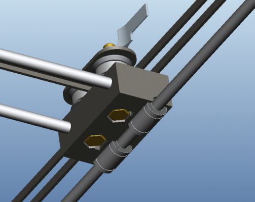
Plan for the dreaded belt cross over. This was one of the last necessary components for the printer that I designed. I had the idea in mind, however I wanted to take measurements and play around with the belt with some 608 bearings in hand before getting a design ready to print.
Belt tensioner setup for the left and right sides. I had ordered the simple spring belt tensioners, however this was an issue because of the amount of actual travel the belt makes in the "worst case" scenario. This threw a loop in the original plan that I didn't think I would have to deal with, but it really wasn't a big issue to overcome. Here's what I came up with, this utilizes two stacked 624 bearings to accommodate/allow variance in belt activity. The assembled picture illustrates the range of adjustment for tensioning the belt.
Edited 2 time(s). Last edit at 05/17/2015 09:20PM by redhatman.
- "Project Locus" - Mostly all printed parts, Corexy, Bowden Setup, 12x12 heatbed, ~1 cubic foot build volume
- SeeMeCNC Rostock Max V2
|
Re: "Project Locus" - *gasp* My Plastic Frame - CoreXY Build Thread May 17, 2015 09:29PM |
Registered: 9 years ago Posts: 57 |
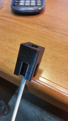
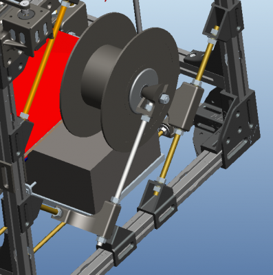
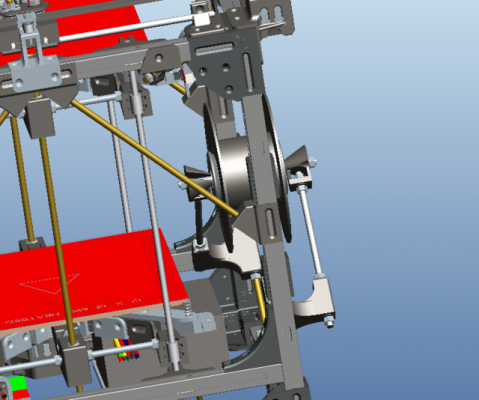
Spool Mount. This was the most recent addition, something I waited until after the machine was running to design. As I said before, the time constraints were because I had split the cost of a prusa last year with my roommate, and I really wanted to get this running by the beginning of may. I figured even if I didn't have a spool holder when it was operational, I could make do, and just print one on the new printer.
I wanted changing the filament spool to be very simple, straightforward, fast, and most of all, a stable and seamless mounting system. This would also have to accommodate the variance in spool styles that different vendors supply.
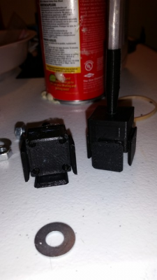
To sum up the features, the spool mounts on tapered cones, which ride on 608 bearings, on a 8mm threaded rod axis. The end nuts (for the axis) can be tightened down, while still allowing smooth spinning motion. The axis mount "holes" are slotted (vs. holes) to aid in easy removal of the spool and axis as an assembly. Everything is oriented with gravity in mind, so even with stuff finger tight, it's all operational.
- "Project Locus" - Mostly all printed parts, Corexy, Bowden Setup, 12x12 heatbed, ~1 cubic foot build volume
- SeeMeCNC Rostock Max V2
|
Re: "Project Locus" - *gasp* My Plastic Frame - CoreXY Build Thread May 17, 2015 09:45PM |
Registered: 9 years ago Posts: 57 |
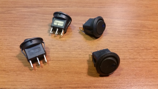
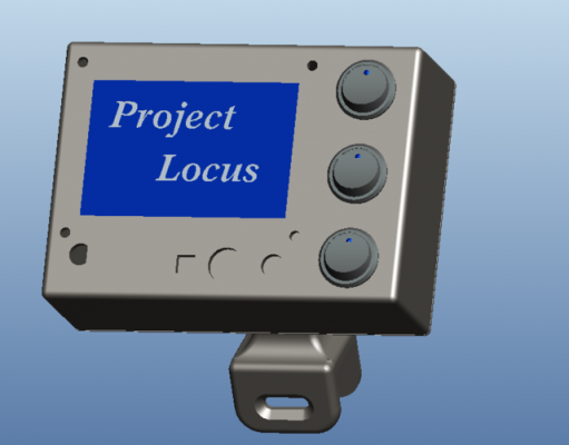
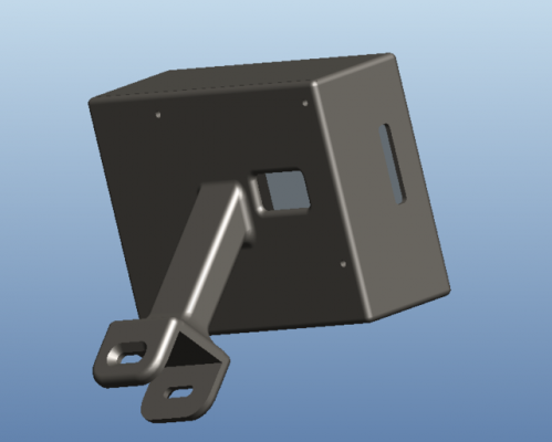
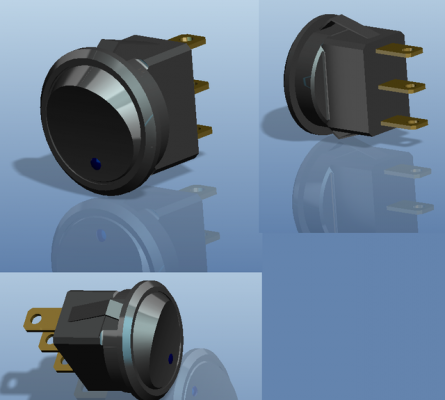
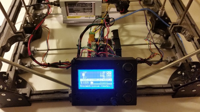
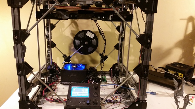
LCD Screen - To be mounted in the front of the machine. The hole in the side is for the SD Card, hole in the back is for running the 2 LCD Cables, and wires corresponding to the switches mounted on the face.
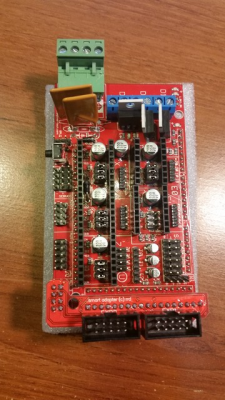
Mounting the ramps board, as well as the power supply. The bottom rods are 1/4" threaded rod, mounted to the bottom frame rails. The purpose of these rods is simply to allow a place to mount stuff. This way nearly everything is contained to the printer chassis itself
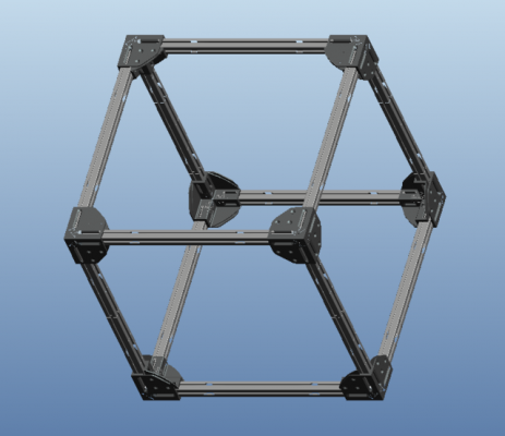
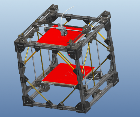
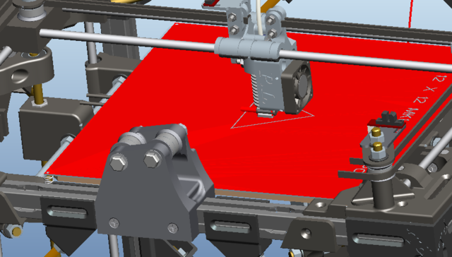
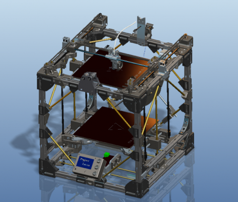
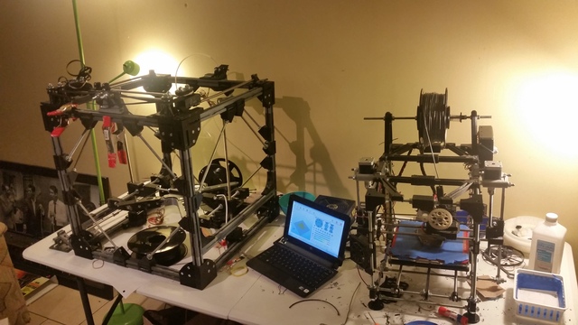
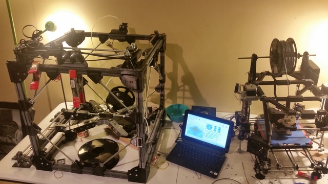
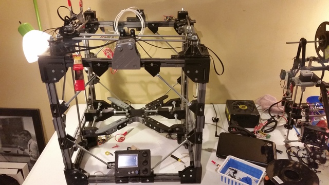
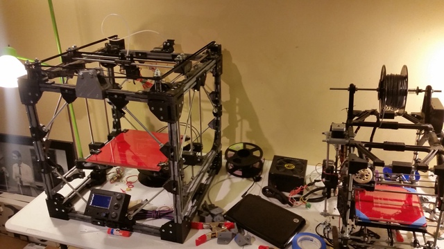
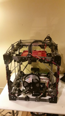
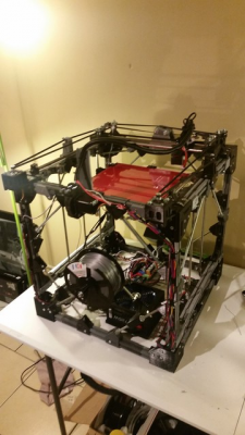
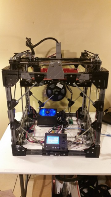
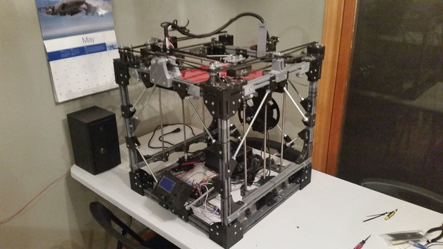
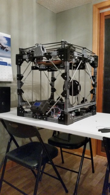
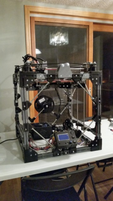
The mostly complete printer assembly (minus the spool mount):
Edited 1 time(s). Last edit at 05/18/2015 09:12AM by redhatman.
- "Project Locus" - Mostly all printed parts, Corexy, Bowden Setup, 12x12 heatbed, ~1 cubic foot build volume
- SeeMeCNC Rostock Max V2
|
Re: "Project Locus" - *gasp* My Plastic Frame - CoreXY Build Thread May 17, 2015 09:54PM |
Registered: 9 years ago Posts: 57 |
Now it's time to make the ideas come to life, and overall see if this thing actually works!
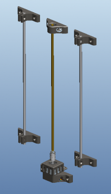
Z axis bearing guides:
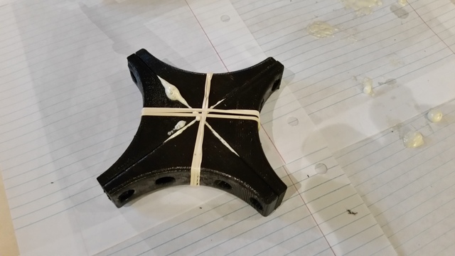
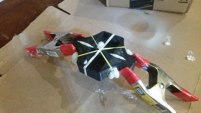
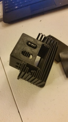
90 Degree Corner Brackets being filled with foam and clamped together. I drilled the holes in the sides which are mated together so (1) they are hidden in the final assembly, (2) they are on a flush and symmetric mating surface for easy clamping with similar parts while curing, leaving the foam with very little place to go.
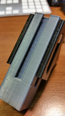
Z axis - 8mm Smooth Rod Clamps
Z Motor Buckets
- "Project Locus" - Mostly all printed parts, Corexy, Bowden Setup, 12x12 heatbed, ~1 cubic foot build volume
- SeeMeCNC Rostock Max V2
|
Re: "Project Locus" - *gasp* My Plastic Frame - CoreXY Build Thread May 17, 2015 09:59PM |
Registered: 9 years ago Posts: 57 |
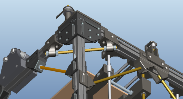
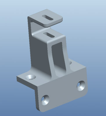
Top brackets which mount on the Top Front corners
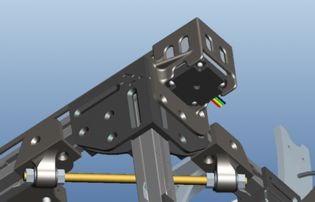
X-Y Motor Buckets
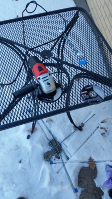
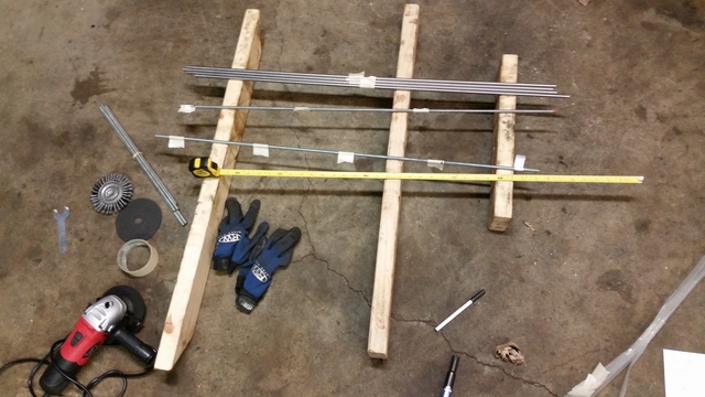
Cutting Rods in the winter yayyy
Gluing some pieces together
- "Project Locus" - Mostly all printed parts, Corexy, Bowden Setup, 12x12 heatbed, ~1 cubic foot build volume
- SeeMeCNC Rostock Max V2
X-Y Motor Buckets
Cutting Rods in the winter yayyy
Gluing some pieces together
- "Project Locus" - Mostly all printed parts, Corexy, Bowden Setup, 12x12 heatbed, ~1 cubic foot build volume
- SeeMeCNC Rostock Max V2
|
Re: "Project Locus" - *gasp* My Plastic Frame - CoreXY Build Thread May 17, 2015 10:07PM |
Registered: 9 years ago Posts: 57 |
Test fitting some brackets
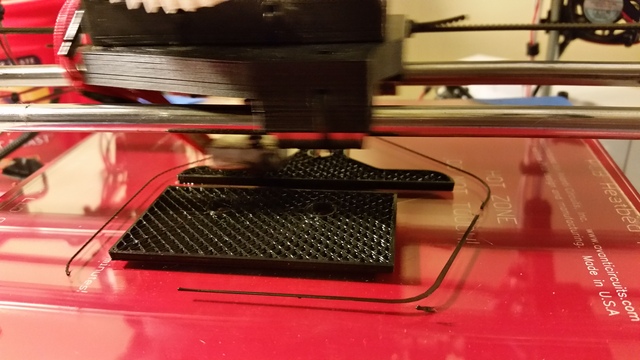
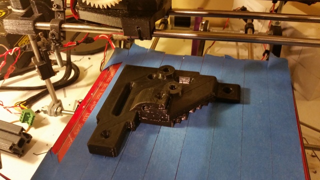
Printing the belt cross over piece
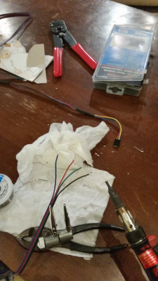
Extending wires, I nearly all steppers, endstops, fans, and the hot end needed the have extensions wired in.
Cutting some more rods at a different time, along with the 8mm smooth rod
Edited 1 time(s). Last edit at 05/17/2015 10:08PM by redhatman.
- "Project Locus" - Mostly all printed parts, Corexy, Bowden Setup, 12x12 heatbed, ~1 cubic foot build volume
- SeeMeCNC Rostock Max V2
|
Re: "Project Locus" - *gasp* My Plastic Frame - CoreXY Build Thread May 17, 2015 10:10PM |
Registered: 9 years ago Posts: 57 |
- "Project Locus" - Mostly all printed parts, Corexy, Bowden Setup, 12x12 heatbed, ~1 cubic foot build volume
- SeeMeCNC Rostock Max V2
|
Re: "Project Locus" - *gasp* My Plastic Frame - CoreXY Build Thread May 17, 2015 10:13PM |
Registered: 9 years ago Posts: 57 |
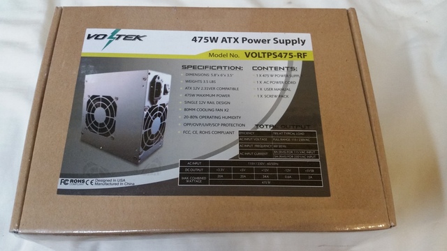
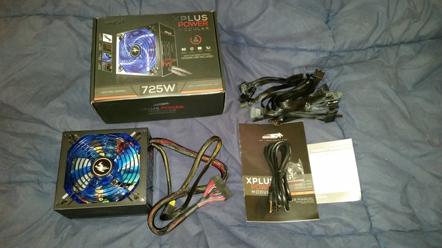
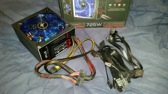
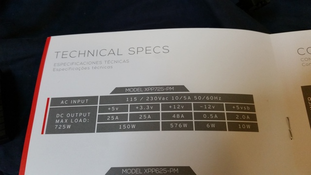
Remember that Diablotek 475W PSU I bought? Yeah... it didn't last more than 10 minutes of use with the hotend at 220 C and the bed at 70 C. So, I was set out to power supply shop again, here's what I settled with.
- "Project Locus" - Mostly all printed parts, Corexy, Bowden Setup, 12x12 heatbed, ~1 cubic foot build volume
- SeeMeCNC Rostock Max V2
|
Re: "Project Locus" - *gasp* My Plastic Frame - CoreXY Build Thread May 17, 2015 10:21PM |
Registered: 9 years ago Posts: 57 |
- "Project Locus" - Mostly all printed parts, Corexy, Bowden Setup, 12x12 heatbed, ~1 cubic foot build volume
- SeeMeCNC Rostock Max V2
|
Re: "Project Locus" - *gasp* My Plastic Frame - CoreXY Build Thread May 17, 2015 10:44PM |
Registered: 9 years ago Posts: 57 |
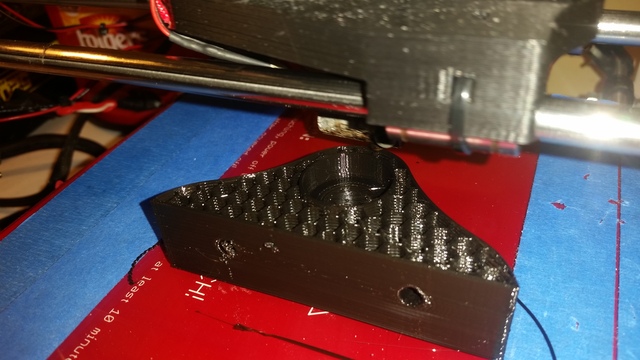
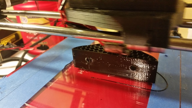
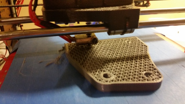
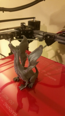
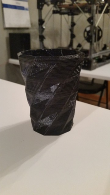
Some test prints (0.4mm nozzle, 0.3mm layer height, PLA)
Edited 1 time(s). Last edit at 05/17/2015 10:45PM by redhatman.
- "Project Locus" - Mostly all printed parts, Corexy, Bowden Setup, 12x12 heatbed, ~1 cubic foot build volume
- SeeMeCNC Rostock Max V2
Edited 1 time(s). Last edit at 05/17/2015 10:45PM by redhatman.
- "Project Locus" - Mostly all printed parts, Corexy, Bowden Setup, 12x12 heatbed, ~1 cubic foot build volume
- SeeMeCNC Rostock Max V2
|
Re: "Project Locus" - *gasp* My Plastic Frame - CoreXY Build Thread May 17, 2015 10:59PM |
Registered: 9 years ago Posts: 57 |
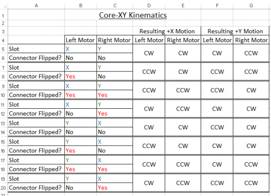
One issue I had once the printer was operational, was that the CoreXY Stepper Kinematics for the XY Motors were not correct. I knew this was nothing more than some connectors flip flopped, however, there were a total of 8 combinations to try. I decided to generate a truth table of sorts vs. keeping track by hand, and manually commanding moves on the printer. This particular table was generated based on the orientation of my two motors at the time, all that was known was the orientation (designated by me) as well as which way the motors would rotate given a desired +X command or a +Y command.
I suppose everyone wants to see a video by now.... In this video, it was printing the battery tray for the new psu (the original tray was made for the psu which didn't even last 5 minutes).
[www.youtube.com]
Features to be added:
- Bridging fan ideally controlled by slicing software
- Bed Fan(s) hooked up to one of the switches
I've also noticed some of the cheapo bearings I used are already going out, there is some rotation under operation which is non-axial (wobbling off axis). So as soon as the new bearings show up, I'll be replacing those.
That's all I got for now, feel free to comment/question/critique as you desire.
Edited 3 time(s). Last edit at 05/18/2015 09:15AM by redhatman.
- "Project Locus" - Mostly all printed parts, Corexy, Bowden Setup, 12x12 heatbed, ~1 cubic foot build volume
- SeeMeCNC Rostock Max V2
|
Re: "Project Locus" - *gasp* My Plastic Frame - CoreXY Build Thread May 18, 2015 05:23AM |
Registered: 9 years ago Posts: 977 |
First, I congratulate you for coming up with your own original design, and both the CAD design work and the impressive assembly work on your printer. The whole venture is admirable and you really have earned everybody's respect.
There are a few points that I would have done differently (e.g. I wouldn't use printed profiles, I honestly prefer them in aluminum), because I feel you have in some cases gone to great lengths to "reinvent the wheel", on the other hand, there are so many brilliant ideas in your printer that this does not in any way tarnish my general impression about it: it's awesome!
There are a few points that I would have done differently (e.g. I wouldn't use printed profiles, I honestly prefer them in aluminum), because I feel you have in some cases gone to great lengths to "reinvent the wheel", on the other hand, there are so many brilliant ideas in your printer that this does not in any way tarnish my general impression about it: it's awesome!

|
Re: "Project Locus" - *gasp* My Plastic Frame - CoreXY Build Thread May 18, 2015 09:04AM |
Registered: 10 years ago Posts: 553 |
Impressive!
Definitely stealing that CoreXY chart for my current build.
greghoge.com
HUGE 3D PRINTER PARTS SALE!!!
Definitely stealing that CoreXY chart for my current build.
greghoge.com
HUGE 3D PRINTER PARTS SALE!!!
|
Re: "Project Locus" - *gasp* My Plastic Frame - CoreXY Build Thread May 21, 2015 02:13PM |
Registered: 9 years ago Posts: 83 |
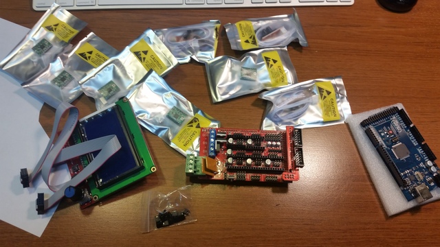
One thing to be aware of, based on personal experience: Looking at your RAMPS board, there are two things you might want to change... First, the right-angle terminal block for the power supply inputs is rated at 10A, and with ABS printing, you'll be pulling 11A+ through it. I'd look for the upgraded 15A connectors (It's a 2 x2 connectors, rather than 1 x4 connector). Sooner or later, the connector will probably start melting. You don't need to change the terminal block mounts on the PCB, just the connector itself.
Secondly, get a heatsink for the Q3 mosfet, and attach it with some heatsink compound. Also make sure it isn't touching the mosfet output terminal block, as it can get hot enough to melt it.
Otherwise, looks good!
Secondly, get a heatsink for the Q3 mosfet, and attach it with some heatsink compound. Also make sure it isn't touching the mosfet output terminal block, as it can get hot enough to melt it.
Otherwise, looks good!
Sorry, only registered users may post in this forum.
