"Project Locus" - *gasp* My Plastic Frame - CoreXY Build Thread
Posted by redhatman
|
Re: "Project Locus" - *gasp* My Plastic Frame - CoreXY Build Thread May 25, 2015 11:01PM |
Registered: 9 years ago Posts: 57 |
Quote
AndrewBCN
First, I congratulate you for coming up with your own original design, and both the CAD design work and the impressive assembly work on your printer. The whole venture is admirable and you really have earned everybody's respect.
There are a few points that I would have done differently (e.g. I wouldn't use printed profiles, I honestly prefer them in aluminum), because I feel you have in some cases gone to great lengths to "reinvent the wheel", on the other hand, there are so many brilliant ideas in your printer that this does not in any way tarnish my general impression about it: it's awesome!
Thank you for the feedback! Yes I understand what you're saying about the aluminum extrusions, and again, thanks for the feedback. As I said, the price was the deciding factor, and trying something different that I believed in was the motivating factor I guess?
Quote
gmh39
Impressive!
Definitely stealing that CoreXY chart for my current build.
Thanks! I should note that again, there is a pattern to the chart, however the orientation I assigned to "flipped" or "not flipped" may not be the same as yours. For reference, at the time of making the chart, I had assigned the left and right motor connectors as "not flipped" when the open end of the connector (the side where you can see the pins through the side), was facing the stepper motor heatsinks.
Quote
grat
One thing to be aware of, based on personal experience: Looking at your RAMPS board, there are two things you might want to change... First, the right-angle terminal block for the power supply inputs is rated at 10A, and with ABS printing, you'll be pulling 11A+ through it. I'd look for the upgraded 15A connectors (It's a 2 x2 connectors, rather than 1 x4 connector). Sooner or later, the connector will probably start melting. You don't need to change the terminal block mounts on the PCB, just the connector itself.
Secondly, get a heatsink for the Q3 mosfet, and attach it with some heatsink compound. Also make sure it isn't touching the mosfet output terminal block, as it can get hot enough to melt it.
Otherwise, looks good!
Thanks for the tips! I'm having a hard time finding those parts, I believe I found what you're talking about with the heatsink.
https://ultimachine.com/sites/default/files/imagecache/product_full/RAMPS_PAcomplete_1.4_0.jpg
If you have a minute, It would be greatly appreciated if you could provide me with a link to what you're referring to. I seem to have no idea where to shop for this type of stuff.
Edited 1 time(s). Last edit at 05/25/2015 11:06PM by redhatman.
- "Project Locus" - Mostly all printed parts, Corexy, Bowden Setup, 12x12 heatbed, ~1 cubic foot build volume
- SeeMeCNC Rostock Max V2
|
Re: "Project Locus" - *gasp* My Plastic Frame - CoreXY Build Thread May 26, 2015 01:13AM |
Registered: 9 years ago Posts: 57 |
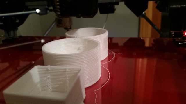
Here's something I've noticed on the last few prints... Any opinions on the odd "thick layers appearance" ? Searching the web leads me to believe it's z-axis wobble.
- "Project Locus" - Mostly all printed parts, Corexy, Bowden Setup, 12x12 heatbed, ~1 cubic foot build volume
- SeeMeCNC Rostock Max V2
- "Project Locus" - Mostly all printed parts, Corexy, Bowden Setup, 12x12 heatbed, ~1 cubic foot build volume
- SeeMeCNC Rostock Max V2
|
Re: "Project Locus" - *gasp* My Plastic Frame - CoreXY Build Thread May 26, 2015 07:41AM |
Registered: 9 years ago Posts: 977 |
|
Re: "Project Locus" - *gasp* My Plastic Frame - CoreXY Build Thread June 10, 2015 03:14AM |
Registered: 9 years ago Posts: 57 |
Here's a small preview of what I've been working on lately, any guesses as to what it's purpose is? (And yes, these are parts proposed for the printer)
Edited 1 time(s). Last edit at 06/10/2015 03:15AM by redhatman.
- "Project Locus" - Mostly all printed parts, Corexy, Bowden Setup, 12x12 heatbed, ~1 cubic foot build volume
- SeeMeCNC Rostock Max V2
Edited 1 time(s). Last edit at 06/10/2015 03:15AM by redhatman.
- "Project Locus" - Mostly all printed parts, Corexy, Bowden Setup, 12x12 heatbed, ~1 cubic foot build volume
- SeeMeCNC Rostock Max V2
|
Re: "Project Locus" - *gasp* My Plastic Frame - CoreXY Build Thread June 10, 2015 06:27AM |
Registered: 8 years ago Posts: 93 |
|
Re: "Project Locus" - *gasp* My Plastic Frame - CoreXY Build Thread June 10, 2015 10:46PM |
Registered: 8 years ago Posts: 6 |
|
Re: "Project Locus" - *gasp* My Plastic Frame - CoreXY Build Thread June 11, 2015 10:55PM |
Registered: 9 years ago Posts: 57 |
Quote
asbo
It looks like some sort of counterweight to me, perhaps to offset the weight of the bed?
Ding ding ding!
 I have modified it already since posting that picture, however the idea remains the same. Hopefully this will eliminate the z-wobble condition.
- "Project Locus" - Mostly all printed parts, Corexy, Bowden Setup, 12x12 heatbed, ~1 cubic foot build volume
- SeeMeCNC Rostock Max V2
|
Re: "Project Locus" - *gasp* My Plastic Frame - CoreXY Build Thread June 12, 2015 06:19AM |
Registered: 8 years ago Posts: 93 |
|
Re: "Project Locus" - *gasp* My Plastic Frame - CoreXY Build Thread June 12, 2015 09:42AM |
Registered: 9 years ago Posts: 346 |
Quote
redhatman
Quote
asbo
It looks like some sort of counterweight to me, perhaps to offset the weight of the bed?
Ding ding ding!I have modified it already since posting that picture, however the idea remains the same. Hopefully this will eliminate the z-wobble condition.
I am curious where you plan to install that, will you change to using belts instead of screws? Or will you remove one of the two trapezoidal screws and make that side of the system passive with the counterweight?
I am myself fighting with z-wobble these days. Last night I abandoned my trapezoidal screw and installed belts, but I am concerned for power cuts that will make the build platform drop the 300 mm. On the other hand, in mechanical engineering we have mostly abandoned counterweight systems in favor of stronger electronics and structures and control systems. Hmm
I will sure keep an eye on your experiences with this counterweight. Interesting.
|
Re: "Project Locus" - *gasp* My Plastic Frame - CoreXY Build Thread June 13, 2015 06:49PM |
Registered: 9 years ago Posts: 57 |
Quote
asbo
I'm in the process of building a CoreXY myself and I'm now thinking a counterweight might be a good idea, may have to pinch your design
Haha go for it, I plan on releasing all of the .stl files and everything associated with this printer within the next week.
Quote
LarsK
I am curious where you plan to install that, will you change to using belts instead of screws? Or will you remove one of the two trapezoidal screws and make that side of the system passive with the counterweight?
I am myself fighting with z-wobble these days. Last night I abandoned my trapezoidal screw and installed belts, but I am concerned for power cuts that will make the build platform drop the 300 mm. On the other hand, in mechanical engineering we have mostly abandoned counterweight systems in favor of stronger electronics and structures and control systems. Hmm
I will sure keep an eye on your experiences with this counterweight. Interesting.
Interesting thoughts! However, that's not what I had in mind. I actually just finished up the design, so I'll print some parts tomorrow and do a test fitting before printing parts for all four corners.
Z-Wobble is such a pesty little thing to have in prints, it's really bothering me and I sure hope this, along with checking the straightness of my rods will cure it. The power cuts concern for your z-axis is the reason I strayed from that in the original design. Although you could certainly do some sort of failsafe feature on yours to absorb the bed in the case of a freefall (power cut, belt breaking, etc). Maybe put a spring, or even two springs (to have a dual rate spring of sorts) to absorb the fall...maybe a cheap damper in there too? Perhaps a shock from a radio controlled car? Either way, the possibilities are endless.
That's interesting you say that about the M.E. Field, why is that being done? I assume to improve the factor of safety, and less maintenance on cable inspection and pulley bearings? The stronger electronics/structures/control systems part seems like a good alternative besides perhaps using more energy when compared to assisted lifting systems.
- "Project Locus" - Mostly all printed parts, Corexy, Bowden Setup, 12x12 heatbed, ~1 cubic foot build volume
- SeeMeCNC Rostock Max V2
|
Re: "Project Locus" - *gasp* My Plastic Frame - CoreXY Build Thread June 13, 2015 07:02PM |
Registered: 9 years ago Posts: 57 |
Edited 1 time(s). Last edit at 06/13/2015 07:39PM by redhatman.
- "Project Locus" - Mostly all printed parts, Corexy, Bowden Setup, 12x12 heatbed, ~1 cubic foot build volume
- SeeMeCNC Rostock Max V2
|
Re: "Project Locus" - *gasp* My Plastic Frame - CoreXY Build Thread June 13, 2015 07:02PM |
Registered: 9 years ago Posts: 57 |
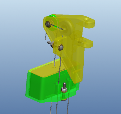
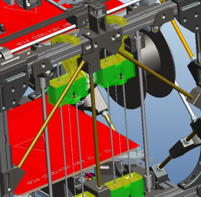
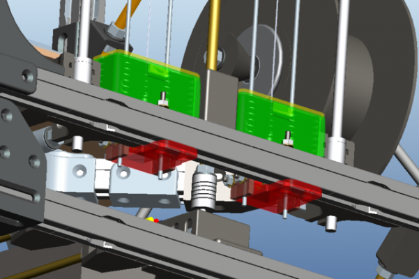
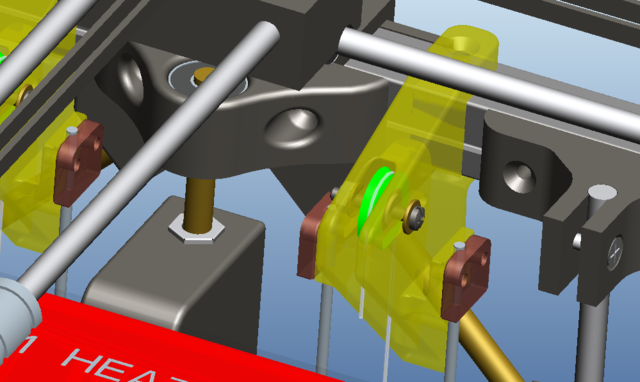
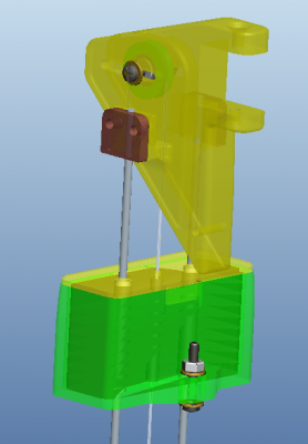
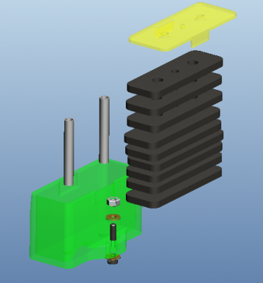
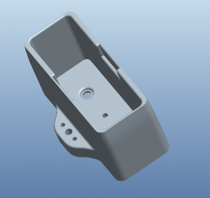
Here's what I've got for an idea of the counterweight system. I placed fasteners in most places to illustrate how stuff will go together. I took off the bed components and weighed them, the assembly weighs 5 lb, 14.6 oz, (5.9125 lb).
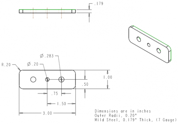
The counterweights are 1" x 3", 7 gauge (0.179") steel plates, with 3 holes cut out. The center hole is for the lifting wire to pass through (I'm using clear picture hanging wire from the hardware store, good for 50lb). The outer two holes are for 1/4" automotive brake line sections to be placed in, which is what the guide rod will run on.
The 1/4" brake line sections will remain entirely enclosed in the printed counterweight assembly, and reside in grooves in the brackets itself.
The guide rails are 1/8" mild steel rod. Although this is not an ideal fit, a 3.2mm rod in a 4.6mm hole isn't all that bad. I figured I'd incorporate the brake line to provide a smooth sliding surface. I plan on cutting out the plates on a plasma table, and want to do very little refinishing (drilling holes, etc).
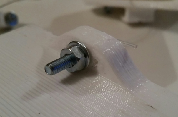
The lifting wire will run from the top, down through the CW assembly, then up through one of the bottom bolt boles, past the screw (under the washer), then back down the hole, and above the washer on the underside. The bends in the wire through the bracket effectively have friction as it is, however the bolt will be tightened to sandwich (clamp) the wire in place.
Each counterweight assembly has 9 plates, weighing ~1.25 lbs for the assembly. This would effectively be lifting 5 lbs of the 5.91 lbs that's currently sitting on the z-motors. I may add a little more weight to try and achieve equilibrium. These are pretty accurate, but will estimates for the weight. I did not get true weight values of small things such as screws, printed part weights, etc... simply because I have not printed the parts yet.
The pulley position is adjustable and rides on a single 624 bearing.
The bracket screws to the extrusions using an upper and lower screw, and will be zip tied to the 45 deg. angled bracket on the side of the machine near the bottom of the bracket (see the hole).
The wire will attach to the heatbed threaded rod using a similar fashion wire-through-bracket style clamp.
--------------- With that being said, what do ya think?
Edited 2 time(s). Last edit at 06/13/2015 07:23PM by redhatman.
- "Project Locus" - Mostly all printed parts, Corexy, Bowden Setup, 12x12 heatbed, ~1 cubic foot build volume
- SeeMeCNC Rostock Max V2
|
Re: "Project Locus" - *gasp* My Plastic Frame - CoreXY Build Thread June 14, 2015 11:02AM |
Registered: 9 years ago Posts: 346 |
It is an interesting design but I am not clear why you think this will help wobble? Wobble is the lag of centricity of you screw. When it rotates it pushes your carriage from side to side. For this reason you should see that the wobble in your printed pieces is exactly with the distance of the pitch on your screw.
The system you have made will only help if you have the problem with your linear rods binding the carriage so that it gets stuck in one side when moving up or down. But the root cause for that happening is your screw pushing the carriage to a side and increasing friction in that side and reducing the other.
Again, that is my point of view with my limited knowledge.
|
Re: "Project Locus" - *gasp* My Plastic Frame - CoreXY Build Thread June 14, 2015 12:04PM |
Registered: 9 years ago Posts: 1,159 |
Quote
LarsK
It is an interesting design but I am not clear why you think this will help wobble? Wobble is the lag of centricity of you screw. When it rotates it pushes your carriage from side to side. For this reason you should see that the wobble in your printed pieces is exactly with the distance of the pitch on your screw.
The system you have made will only help if you have the problem with your linear rods binding the carriage so that it gets stuck in one side when moving up or down. But the root cause for that happening is your screw pushing the carriage to a side and increasing friction in that side and reducing the other.
Again, that is my point of view with my limited knowledge.
It is also more pronounced if the lead screws are constrained at both ends which is why the Std Prusa style machine have the screw mounted only at the motor ends and left to move at the upper end in a larger than required hole for it.
If they are constrained at both top and bottom then any out of true will be transmitted into the Bed as Z Wobble.
Doug
|
Re: "Project Locus" - *gasp* My Plastic Frame - CoreXY Build Thread June 14, 2015 01:29PM |
Registered: 9 years ago Posts: 346 |
Quote
dougal1957
Quote
LarsK
It is an interesting design but I am not clear why you think this will help wobble? Wobble is the lag of centricity of you screw. When it rotates it pushes your carriage from side to side. For this reason you should see that the wobble in your printed pieces is exactly with the distance of the pitch on your screw.
The system you have made will only help if you have the problem with your linear rods binding the carriage so that it gets stuck in one side when moving up or down. But the root cause for that happening is your screw pushing the carriage to a side and increasing friction in that side and reducing the other.
Again, that is my point of view with my limited knowledge.
It is also more pronounced if the lead screws are constrained at both ends which is why the Std Prusa style machine have the screw mounted only at the motor ends and left to move at the upper end in a larger than required hole for it.
If they are constrained at both top and bottom then any out of true will be transmitted into the Bed as Z Wobble.
Doug
I have seen that and I don't think it is a concept that will make it into the " best practices" book. You are putting all the axial load on the small stepper bearings and they are not designed for that. I see that it works on prusa but on a big coreXY with a huge bed I don't think that is the solution - unless you make a counterweight system like redhatman is doing so that the bed Weight is reduced. Then it is feasible.
A picture example for those who wants to see what it looks like
[lh6.googleusercontent.com]
Wobble is easily solved by putting a motor and coupling at the end of this:
But when you go that route you quickly need special parts or machining on a lathe. That is why I have for now abandoned it.
|
Re: "Project Locus" - *gasp* My Plastic Frame - CoreXY Build Thread June 14, 2015 01:51PM |
Registered: 9 years ago Posts: 1,159 |
Quote
LarsK
Quote
dougal1957
Quote
LarsK
It is an interesting design but I am not clear why you think this will help wobble? Wobble is the lag of centricity of you screw. When it rotates it pushes your carriage from side to side. For this reason you should see that the wobble in your printed pieces is exactly with the distance of the pitch on your screw.
The system you have made will only help if you have the problem with your linear rods binding the carriage so that it gets stuck in one side when moving up or down. But the root cause for that happening is your screw pushing the carriage to a side and increasing friction in that side and reducing the other.
Again, that is my point of view with my limited knowledge.
It is also more pronounced if the lead screws are constrained at both ends which is why the Std Prusa style machine have the screw mounted only at the motor ends and left to move at the upper end in a larger than required hole for it.
If they are constrained at both top and bottom then any out of true will be transmitted into the Bed as Z Wobble.
Doug
I have seen that and I don't think it is a concept that will make it into the " best practices" book. You are putting all the axial load on the small stepper bearings and they are not designed for that. I see that it works on prusa but on a big coreXY with a huge bed I don't think that is the solution - unless you make a counterweight system like redhatman is doing so that the bed Weight is reduced. Then it is feasible.
A picture example for those who wants to see what it looks like
[lh6.googleusercontent.com]
Wobble is easily solved by putting a motor and coupling at the end of this:
But when you go that route you quickly need special parts or machining on a lathe. That is why I have for now abandoned it.
I agree with the loading bit which is why I have mine mounted in Self Aligning Bearing Blocks to take the vertical load with only one motor (A Large Nema 23 290 oz torque) then the 3 in a triangular pattern linked by a endless toothed belt as used in the Leapfrog printer's
|
Re: "Project Locus" - *gasp* My Plastic Frame - CoreXY Build Thread June 14, 2015 04:37PM |
Registered: 9 years ago Posts: 57 |
Quote
LarsK
It is an interesting design but I am not clear why you think this will help wobble? Wobble is the lag of centricity of you screw. When it rotates it pushes your carriage from side to side. For this reason you should see that the wobble in your printed pieces is exactly with the distance of the pitch on your screw.
The system you have made will only help if you have the problem with your linear rods binding the carriage so that it gets stuck in one side when moving up or down. But the root cause for that happening is your screw pushing the carriage to a side and increasing friction in that side and reducing the other.
Again, that is my point of view with my limited knowledge.
I apologize, I guess I never mentioned the part about straightening the 8mm rod. Here's my thought on how/why this counterweight system will help.
- The machine has progressively developed worse z-wobble with each print. (the first prints didn't have wobble near as bad)
- An 8mm Rod really isn't that hard to bend over a 1-2 foot span.
-There's over 5 lbs of weight constantly sitting on the rods.
- Lets assume that somehow, somewhere along the line, one of the rods developed a bend. Being under constant load, and varrying rotations, I assume this is where the wobble has been getting worse.
The counterweight system proposed would be done along with removing and ensuring straightness of the 8mm rods. The counterweight system is moreso to prevent the same bending from happening again.
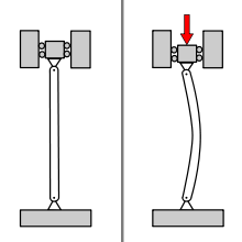
Given I have the 8mm to 5mm couplings, I can visually watch them squish and flex as the bed moves. It's not as terrible as those words make it sound, but it's certainly not desirable to have a 3 lb axial load on each motor.
Edited 1 time(s). Last edit at 06/14/2015 04:43PM by redhatman.
- "Project Locus" - Mostly all printed parts, Corexy, Bowden Setup, 12x12 heatbed, ~1 cubic foot build volume
- SeeMeCNC Rostock Max V2
|
Re: "Project Locus" - *gasp* My Plastic Frame - CoreXY Build Thread June 24, 2015 10:29AM |
Registered: 9 years ago Posts: 977 |
@ redhatmanQuote
dougal1957
Quote
LarsK
It is an interesting design but I am not clear why you think this will help wobble? Wobble is the lag of centricity of you screw. When it rotates it pushes your carriage from side to side. For this reason you should see that the wobble in your printed pieces is exactly with the distance of the pitch on your screw.
The system you have made will only help if you have the problem with your linear rods binding the carriage so that it gets stuck in one side when moving up or down. But the root cause for that happening is your screw pushing the carriage to a side and increasing friction in that side and reducing the other.
Again, that is my point of view with my limited knowledge.
It is also more pronounced if the lead screws are constrained at both ends which is why the Std Prusa style machine have the screw mounted only at the motor ends and left to move at the upper end in a larger than required hole for it.
If they are constrained at both top and bottom then any out of true will be transmitted into the Bed as Z Wobble.
Doug
Hmmm, I agree 100% with both LarsK and Doug, and I am not sure that removing the 2.5kg weight on the 8mm rods (using a complex counterweight system) and straightening them will solve your Z-wobble problem. But that is from my limited knowledge and experience: I have only used rather soft (easy to bend) 5mm galvanized carbon steel rods on my various Prusa i3 and P3Steel printers and not once I saw Z-wobble as bad as you have shown in your pictures above. In fact I never detected any significant Z-wobble distortion in any of my prints up until now on any of my printers, even though some of the 5mm rods I am using are clearly not straight! So I guess Josef Prusa's solution has some merit to it: simple, inexpensive and does the job!
Based on the above I would suggest you think about and try to design a K.I.S.S. solution to your Z-wobble problem.
Just my $0.02.

|
Re: "Project Locus" - *gasp* My Plastic Frame - CoreXY Build Thread June 26, 2015 01:04AM |
Registered: 9 years ago Posts: 57 |
Quote
AndrewBCN
@ redhatmanQuote
dougal1957
Quote
LarsK
It is an interesting design but I am not clear why you think this will help wobble? Wobble is the lag of centricity of you screw. When it rotates it pushes your carriage from side to side. For this reason you should see that the wobble in your printed pieces is exactly with the distance of the pitch on your screw.
The system you have made will only help if you have the problem with your linear rods binding the carriage so that it gets stuck in one side when moving up or down. But the root cause for that happening is your screw pushing the carriage to a side and increasing friction in that side and reducing the other.
Again, that is my point of view with my limited knowledge.
It is also more pronounced if the lead screws are constrained at both ends which is why the Std Prusa style machine have the screw mounted only at the motor ends and left to move at the upper end in a larger than required hole for it.
If they are constrained at both top and bottom then any out of true will be transmitted into the Bed as Z Wobble.
Doug
Hmmm, I agree 100% with both LarsK and Doug, and I am not sure that removing the 2.5kg weight on the 8mm rods (using a complex counterweight system) and straightening them will solve your Z-wobble problem. But that is from my limited knowledge and experience: I have only used rather soft (easy to bend) 5mm galvanized carbon steel rods on my various Prusa i3 and P3Steel printers and not once I saw Z-wobble as bad as you have shown in your pictures above. In fact I never detected any significant Z-wobble distortion in any of my prints up until now on any of my printers, even though some of the 5mm rods I am using are clearly not straight! So I guess Josef Prusa's solution has some merit to it: simple, inexpensive and does the job!
Based on the above I would suggest you think about and try to design a K.I.S.S. solution to your Z-wobble problem.
Just my $0.02.
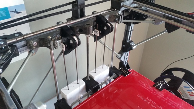
The way I eventually justified pulling the trigger on building the counterweight system was for a few reasons; Low cost, I had all of the supplies minus the brake line and steel rod, relatively simple, and no disassembly required to install it. However the main reason was probably that it's function couldn't possibly harm the printer. Even with the system installed, the worst that can happen is the z-wobble still exists, but on the bright side, there isnt 5-6 lbs sitting on the steppers.
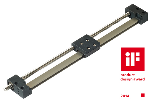
I truly like the idea of the smaller rods as a few have mentioned (I believe that's what led me to do the counterweights). I had looked around at smaller rods to use, however I was very nervous thinking about how such small rods would handle the load. I believe this would work with much less issue on a machine with top mounted steppers (where the threaded rod is in tension).
With that being said, now that I have the counterweight system installed, I can safely convince myself that the weight of the bed is supported, and will begin working on converting to smaller rods. From what I'm thinking now, I can convert everything for around $5. As far as the z-wobble, it still does exist, but has improved. I am also starting to believe that it may be much more apparent when using Cura. I'm not sure if there's much logic to it, however when I use craftware the prints seem to turn out with less z-wobble. Coincidence? Maybe.
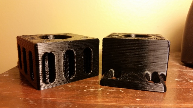
Here's a print I did the other day of some new top halves of the z-motor mounts (I slotted the holes for fine adjustment of the z-motor "tilt"). This is at 0.3mm layer height.
- "Project Locus" - Mostly all printed parts, Corexy, Bowden Setup, 12x12 heatbed, ~1 cubic foot build volume
- SeeMeCNC Rostock Max V2
|
Re: "Project Locus" - *gasp* My Plastic Frame - CoreXY Build Thread June 26, 2015 01:09AM |
Registered: 9 years ago Posts: 57 |
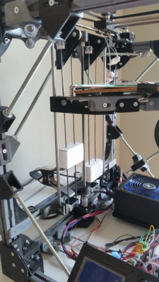
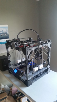
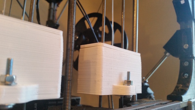
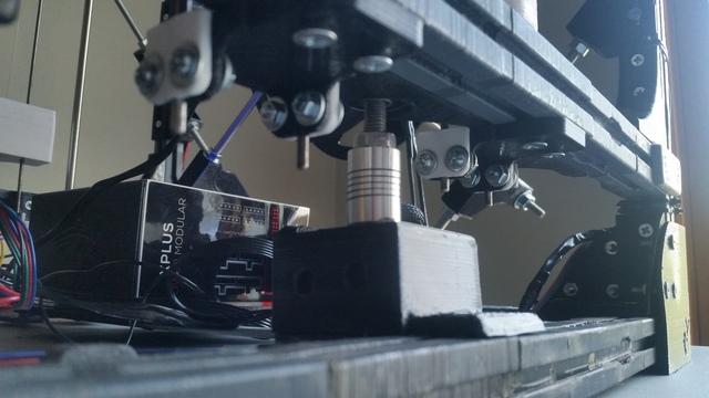
Here's a video of it printing one of the weight box shells for the counterweight system. I decided to ramp up the speed a bit and see what happened.
[www.youtube.com]
Also, some updated pictures
- "Project Locus" - Mostly all printed parts, Corexy, Bowden Setup, 12x12 heatbed, ~1 cubic foot build volume
- SeeMeCNC Rostock Max V2
[www.youtube.com]
Also, some updated pictures
- "Project Locus" - Mostly all printed parts, Corexy, Bowden Setup, 12x12 heatbed, ~1 cubic foot build volume
- SeeMeCNC Rostock Max V2
|
Re: "Project Locus" - *gasp* My Plastic Frame - CoreXY Build Thread June 26, 2015 01:10AM |
Registered: 9 years ago Posts: 57 |
- "Project Locus" - Mostly all printed parts, Corexy, Bowden Setup, 12x12 heatbed, ~1 cubic foot build volume
- SeeMeCNC Rostock Max V2
Sorry, only registered users may post in this forum.

