G&C Printer
Posted by filipeCampos
|
Re: G&C Printer September 28, 2015 05:51AM |
Registered: 8 years ago Posts: 346 |
Quote
David J
I may be using a different method for mounting the E3Dv6, but I'm not sure yet. The setup on my delta works very well, so I will probably try to take the whole thing over to this printer. Your design gives a lot of flexibility, which helps a lot.
If you create new pieces or change the design can you please share with me or share in thingiverse. It will be great to add more setups and upgrades to the printer.
If you bowden setup work well in the delta i sure it will work well too in this printer. For me i think to put on top of the carriage an mk8 or greg extruder. the main vantage of the corexy it allow to put heavy extruder(s) in the carriage.
|
Re: G&C Printer September 28, 2015 06:16AM |
Registered: 9 years ago Posts: 893 |
The piece I'm talking about is already on Thingiverse - here.
It's designed in OpenSCAD so I can change the top to suit this printer (if I need to). I've already changed it slightly, to give a smoother air flow. I will publish any other changes I make for this printer.
I do like direct extruders, but I have all the parts needed for a bowden arrangement. This printer allows me to experiment with all sorts of things, which was the other reason for selecting it!
Edited 1 time(s). Last edit at 09/28/2015 06:18AM by David J.
|
Re: G&C Printer September 28, 2015 03:09PM |
Registered: 8 years ago Posts: 346 |
Hi David,
I have upload a new version of the bom file with the information of the screw and nuts necessary.
I strongly recommend to use nuts nylok on the moving parts and washers to distribute better the force in the pla/abs, if you can replace all nuts to nylok.
The T-nuts you do not need to buy, there are from the 100 pieces bag. The 100 t-nuts are not enough to secure the printed panels, you can print some pla t-nuts or better by more 60 t-nuts M4.
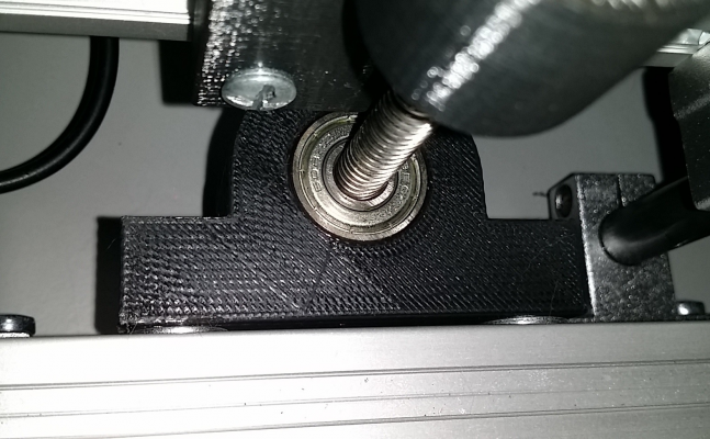
I have remember something important, the pla piece that secure the Z screw at the bottom of the printer do not have the correct dimension. You need to increase 1,5 mm to the pieces, check the photo to understand better. In my printer i have corrected the problem adding M4 washer between the piece and the 2020 extrusion.
I have corrected this problem and updated the 3d project.
Edited 1 time(s). Last edit at 09/28/2015 03:17PM by filipeCampos.
|
Re: G&C Printer September 28, 2015 03:20PM |
Registered: 9 years ago Posts: 893 |
I'd just noticed that you had uploaded the new BOM - but I hadn't noticed the new Z support. I'll go and download that one as well... 
Thank you!
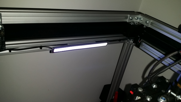
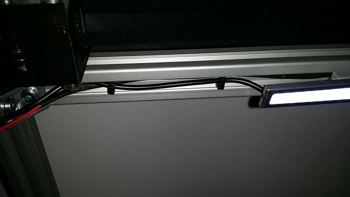
One question - am I right in thinking that the angled thing on the inside of the top front extrusion is an LED support? And the things going round the inside of the top are supports for the LED wires?
Edited 2 time(s). Last edit at 09/28/2015 03:23PM by David J.

Thank you!
One question - am I right in thinking that the angled thing on the inside of the top front extrusion is an LED support? And the things going round the inside of the top are supports for the LED wires?
Edited 2 time(s). Last edit at 09/28/2015 03:23PM by David J.
|
Re: G&C Printer September 28, 2015 03:40PM |
Registered: 8 years ago Posts: 346 |
yes, is the support for the led.
i have used one of the next leds: [www.ebay.com]
the little support are used to support the wires of the led and one endstop
Edited 1 time(s). Last edit at 09/28/2015 06:15PM by filipeCampos.
i have used one of the next leds: [www.ebay.com]
the little support are used to support the wires of the led and one endstop
Edited 1 time(s). Last edit at 09/28/2015 06:15PM by filipeCampos.
|
Re: G&C Printer September 29, 2015 06:09AM |
Registered: 9 years ago Posts: 893 |
Hmm... those LED strips are 7W - maybe I'll print that piece in ABS...
I must say that the more I look at this design, the more I appreciate how much effort has gone into it. I know that the basics of the core-xy mechanism were set down by zelogik, but you've made a good job of the frame and layout. I'm not sure I'll print the panels as they will take a lot of time and filament; I'll probably cut them out of plastic or aluminium sheet.
A couple of extra questions:
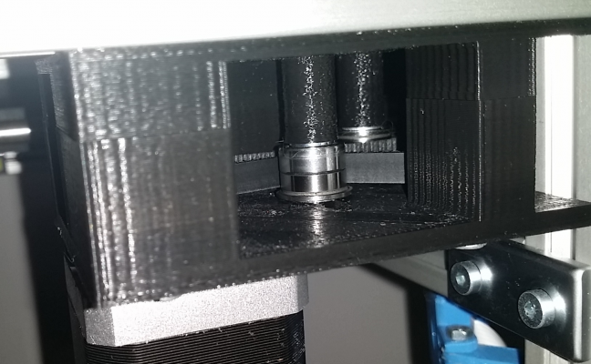
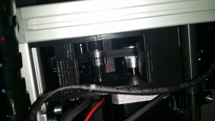
Am I right in thinking that each idler is made up of 2 of the bearings, with flanges to the outside? Do you put a washer between each bearing, to stop them binding?
What size is the bearing that holds the bottom of the Z axis screw? (it's not in the BOM)
To save me the effort of working it out - which I won't be able to do until the belts are fitted - which motor is X and which is Y?
Thanks,
David
|
Re: G&C Printer September 29, 2015 07:06AM |
Registered: 8 years ago Posts: 346 |
Quote
David J
Hmm... those LED strips are 7W - maybe I'll print that piece in ABS...
The led heat up a little and is better in abs. I have printed in pla, so far is ok but i have noted the zone of the led get hot very quick.
Using acrylic or aluminium sheet is way better. I have first try to use black acrylic sheet but i not found any place where it was possible to cut with an laser. And is a more expensive solution.Quote
David J
I'm not sure I'll print the panels as they will take a lot of time and filament; I'll probably cut them out of plastic or aluminium sheet.
If you have acess to a laser cut or something similar you can add completes and better looking panels.
Yes, each idler is made of 2 flanged bearings.Quote
David J
Am I right in thinking that each idler is made up of 2 of the bearings, with flanges to the outside?
The flanged bearings used: [www.ebay.com]
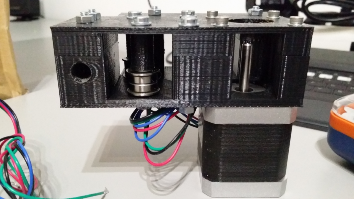
The support of the x and y motors use 4 not flanged bearing to make tension in the belt.
No. The 2 bearings have the outside wall in direct contact in the middle. I use 2 M4 washers to force that only the inside of the bearing is in contact with the plastic piece.Quote
David J
Do you put a washer between each bearing, to stop them binding?
The idler is mounted in this order: M4 washer + flanged bearing + flanged bearing + M4 washer
There is no space to put an third M4 washer in the middle.
I forget to count the 2 M4 washer for each idler, added the info in the bom file.
is a simple 608ZZ. The piece is important to cut the vibrations of the Z when rotation in high speed. I have added 1,5 mm to this piece, but i not sure if is the correct dimension. this error have happened because the aluminum SH12A (http://www.ebay.com/itm/300553708067) do not have the dimensions i was expecting. You can add an second piece between the coupler and the lead screw, you only need to put the back 2020 bar a little more above. this bar bar is put where to support two filament support when the printer will go dual extuder.Quote
David J
What size is the bearing that holds the bottom of the Z axis screw? (it's not in the BOM)
in my case (repetier firmware) X is the left motor, Y the right.Quote
David J
To save me the effort of working it out - which I won't be able to do until the belts are fitted - which motor is X and which is Y?
But to correct you only need to swap the cables in the board.
Edited 1 time(s). Last edit at 09/29/2015 08:56AM by filipeCampos.
|
Re: G&C Printer September 29, 2015 10:53AM |
Registered: 9 years ago Posts: 893 |
One observation: if you want to use nylok nuts then the M4 x 40mm screws won't be long enough - I made up the rear-left motor mount using some old PLA to check on my slicer settings, and by the time I'd assembled it the M4 screw doesn't stick far enough out of the piece to engage with the nylon ring in the nylok nut. You will have to specify 45mm screws, or even 50mm if you can't find that size (I've had great difficulty, but I'm still looking). I have loads of 40mm screws, so I may use those with ordinary nuts and put loctite on the threads (once I know it's working!). UPDATE: Just found some 45mm screws on ebay! 
Good news about the 608 bearing - I already have a few of those. I can always pack the bearing mount out a little if necessary - only a minor detail.
Edited 1 time(s). Last edit at 09/29/2015 11:06AM by David J.

Good news about the 608 bearing - I already have a few of those. I can always pack the bearing mount out a little if necessary - only a minor detail.
Edited 1 time(s). Last edit at 09/29/2015 11:06AM by David J.
|
Re: G&C Printer September 29, 2015 11:21AM |
Registered: 8 years ago Posts: 346 |
About the nylock your are correct, they must be at least 5mm longer in case you replace the normal nuts.
I have used only nylock in the moving pieces, this is the reason i put the 40mm was the dimensions of the M4 in not moving pieces.
This information is important, i will update the bom file indicating this.
I have used only nylock in the moving pieces, this is the reason i put the 40mm was the dimensions of the M4 in not moving pieces.
This information is important, i will update the bom file indicating this.
|
Re: G&C Printer October 01, 2015 06:26AM |
Registered: 9 years ago Posts: 893 |
|
Re: G&C Printer October 01, 2015 07:13AM |
Registered: 8 years ago Posts: 346 |
I have used infill 30% and 1.2mm for all the walls. I think an infill between 25% and 35% will be good.
One important factor is to avoid to print with low temperature because the layer must be well connected together.
In my case when i print supports pieces an print with high temperature (195ºC - 205ºC) that an normally use, i use low speeds and redirect the piece to avoid bridges.
I not sure what is the best pla or abs?
What i know is that abs is a lot better for piece in contact with object that have high temperature (hotend) and pla is better for rigidity.
For example the piece that secure my hotend is already curve (printed in pla). I already printed a new one (backup) and i have ordered the next pieces was an definite solution for the problem.
[www.ebay.com]
Edited 1 time(s). Last edit at 10/01/2015 07:14AM by filipeCampos.
|
Re: G&C Printer October 01, 2015 07:17AM |
Registered: 9 years ago Posts: 893 |
|
Re: G&C Printer October 01, 2015 07:55AM |
Registered: 9 years ago Posts: 893 |
|
Re: G&C Printer October 01, 2015 08:49AM |
Registered: 8 years ago Posts: 346 |
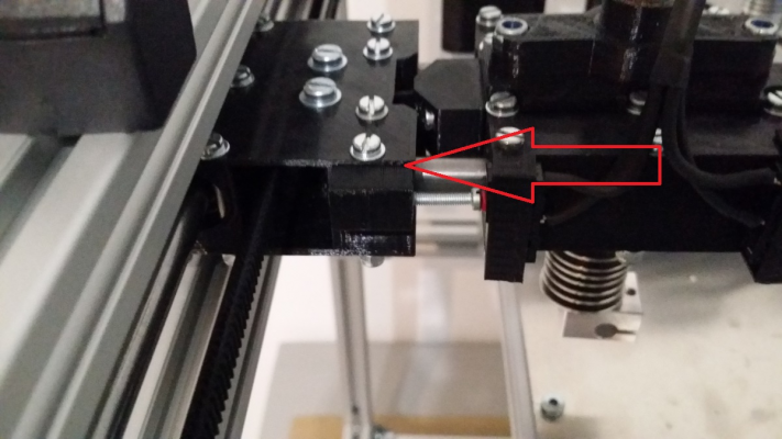
Before printing the pieces that support the x axis, you can join the object of the upper side with the object file that support the screw that adjust the min x endstop. If you will use an max x endstop you can do the same.
At the time i have printed in separate pieces because i was not sure of the correct position, then i have glued the 2 pieces together. But having only on piece is better...
Edited 2 time(s). Last edit at 10/01/2015 08:59AM by filipeCampos.
At the time i have printed in separate pieces because i was not sure of the correct position, then i have glued the 2 pieces together. But having only on piece is better...
Edited 2 time(s). Last edit at 10/01/2015 08:59AM by filipeCampos.
|
Re: G&C Printer October 03, 2015 07:39AM |
Registered: 9 years ago Posts: 893 |
I've never tried joining 2 STL files together... is it easy to do? Or is it something to do in 123D?
Going back to the discussion regarding direct extruders, I saw this thing in Thingiverse: http://www.thingiverse.com/thing:285741. It's certainly smaller than a standard Wade's extruder, and the only drawback seems to be that you have to turn the extruder motor's acceleration down because the motor's gears are delicate (according to the designer). Might revisit that when my printer nears completion.
If I ever get there... I was busy printing parts on my Prusa i3, and noticed that it wasn't producing the normal quality. Then I looked at it and thought "it will be nice to have a printer that doesn't wobble around so much... hang on, the direct extruder shouldn't be wobbling THAT much!". A plastic bracket that holds the extruder & hot-end to the X carriage had split.
That took me the best part of a day to make a new bracket out of aluminium (I couldn't print a new one), then I found that the IR Z sensor bracket was now too long, and I had to make a new one of those. This was followed by a session of re-setting Marlin to allow for the new distance between the nozzle and the sensor. A day and a half wasted!
Still, it's working now, so printing continues...
Edited 1 time(s). Last edit at 10/03/2015 07:40AM by David J.
Going back to the discussion regarding direct extruders, I saw this thing in Thingiverse: http://www.thingiverse.com/thing:285741. It's certainly smaller than a standard Wade's extruder, and the only drawback seems to be that you have to turn the extruder motor's acceleration down because the motor's gears are delicate (according to the designer). Might revisit that when my printer nears completion.
If I ever get there... I was busy printing parts on my Prusa i3, and noticed that it wasn't producing the normal quality. Then I looked at it and thought "it will be nice to have a printer that doesn't wobble around so much... hang on, the direct extruder shouldn't be wobbling THAT much!". A plastic bracket that holds the extruder & hot-end to the X carriage had split.

That took me the best part of a day to make a new bracket out of aluminium (I couldn't print a new one), then I found that the IR Z sensor bracket was now too long, and I had to make a new one of those. This was followed by a session of re-setting Marlin to allow for the new distance between the nozzle and the sensor. A day and a half wasted!

Still, it's working now, so printing continues...
Edited 1 time(s). Last edit at 10/03/2015 07:40AM by David J.
|
Re: G&C Printer October 03, 2015 01:01PM |
Registered: 8 years ago Posts: 346 |
Yes you can merge pieces together using 123D design, is very easy to do.
1) open the project of the printer
2) select merge
3) click in the 2 or more piece to merge
4) click again in the merge button (same was step 2)
At this point you have the merged object, export to stl and print. No more need of glue
Was the direct extruder i have created a new one using the direct mk8 desing was base . Already printed and now making the installation. Still not sure if the extruder will work or not...
[www.thingiverse.com]
About your prusa is bad luck, sometimes shit happens..
1) open the project of the printer
2) select merge
3) click in the 2 or more piece to merge
4) click again in the merge button (same was step 2)
At this point you have the merged object, export to stl and print. No more need of glue

Was the direct extruder i have created a new one using the direct mk8 desing was base . Already printed and now making the installation. Still not sure if the extruder will work or not...
[www.thingiverse.com]
About your prusa is bad luck, sometimes shit happens..
|
Re: G&C Printer October 03, 2015 01:43PM |
Registered: 9 years ago Posts: 893 |
OK - that merge sounds easy... we will see! 
That extruder looks interesting - I'll let you try it first, and wait for your report!
Looking back, that extruder part was doomed to fail - all of the extruder forces pivot on that bracket when the X-axis moves back and forth quickly, so it really isn't a surprise that it failed over time. The new bracket is made of aluminium angle 3.2mm thick, so I don't think that wll fail in a hurry!

That extruder looks interesting - I'll let you try it first, and wait for your report!

Looking back, that extruder part was doomed to fail - all of the extruder forces pivot on that bracket when the X-axis moves back and forth quickly, so it really isn't a surprise that it failed over time. The new bracket is made of aluminium angle 3.2mm thick, so I don't think that wll fail in a hurry!
|
Re: G&C Printer October 03, 2015 02:01PM |
Registered: 9 years ago Posts: 893 |
I tried the merge - and got confused! Selected the two parts (Y-carriage top and end-stop block), clicked on combine, and got the question "click on source mesh" and "click on target mesh". Now I have no idea what to do...
...time to read the manual!
Edited 1 time(s). Last edit at 10/03/2015 02:15PM by David J.
...time to read the manual!
Edited 1 time(s). Last edit at 10/03/2015 02:15PM by David J.
|
Re: G&C Printer October 03, 2015 02:23PM |
Registered: 9 years ago Posts: 893 |
|
Re: G&C Printer October 03, 2015 04:32PM |
Registered: 8 years ago Posts: 346 |
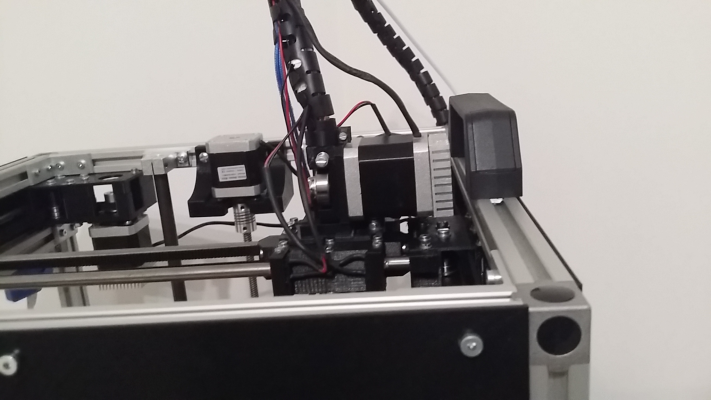
Well, i have installed the direct extruder and made a little print. So far everything look good, is working...
But i need to make more tests to be sure.
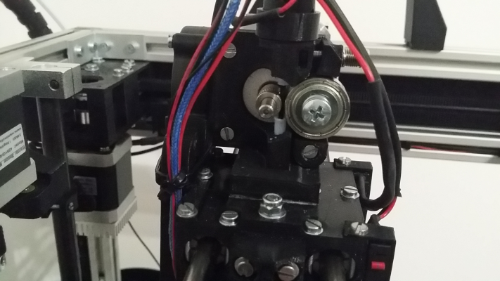
There are 2 ptfe tubes, one that goes from the bottom of extruder to the end of the hotend, and the second to the right side of the printer to the top of the extruder.
I using a big 2.5A motor, a little motor 1.7A will be better. I have printed at 70mm/s and not see any artifact in the walls. I have reduced the retraction from 5mm to 1.5mm.
used super glue to connect the extruder to the pieces that secure the hotend.
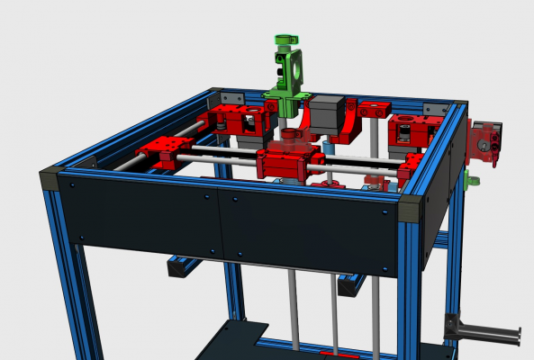
The 3d project of the extruder:
The direct extruder in the printer:
Edited 2 time(s). Last edit at 10/03/2015 04:36PM by filipeCampos.
|
Re: G&C Printer October 03, 2015 04:32PM |
Registered: 9 years ago Posts: 893 |
Hello again Filipe,
I have another query - should the right-rear motor mount have a movable idler to tension the belt? It isn't shown on the 123D model, but it seems sensible to have one (and there's a slot for it). Your photos show a screw in that location, but it's not possible to see if there is a pair of bearings there.
If there is supposed to be an idler there, then your BOM needs an update - you will need a total of 28 F624ZZ bearings (14 pairs). Even if there isn't an idler in that location, the BOM says 25 bearings, which wouldn't work either!
Cheers,
David
I have another query - should the right-rear motor mount have a movable idler to tension the belt? It isn't shown on the 123D model, but it seems sensible to have one (and there's a slot for it). Your photos show a screw in that location, but it's not possible to see if there is a pair of bearings there.
If there is supposed to be an idler there, then your BOM needs an update - you will need a total of 28 F624ZZ bearings (14 pairs). Even if there isn't an idler in that location, the BOM says 25 bearings, which wouldn't work either!

Cheers,
David
|
Re: G&C Printer October 03, 2015 04:55PM |
Registered: 8 years ago Posts: 346 |
Quote
David J
should the right-rear motor mount have a movable idler to tension the belt?
Yes, both left and right have an idler.
the left use F624ZZ (bottom) + 624ZZ (top):
the right use 2 x 624ZZ:
In total you need the 25 F624ZZ and plus 3 624ZZ.
I forgot to add these 3 624ZZ in the bom file and the 3d project is missing the info about these idlers.
When i have more time i will correct this.
David, thanks for this info...
|
Re: G&C Printer October 03, 2015 05:02PM |
Registered: 9 years ago Posts: 893 |
|
Re: G&C Printer October 03, 2015 05:18PM |
Registered: 8 years ago Posts: 346 |
Quote
David J
I'm using F624ZZ everywhere - should work OK (he said, hopefully).
F624ZZ everywhere will work fine...
Updated the bom file and 123dx project.
I have added the missing idler and the new direct extruder.
|
Re: G&C Printer October 03, 2015 05:28PM |
Registered: 9 years ago Posts: 893 |
The extruder looks interesting. Is it for 1.75mm or 3mm?
It's hard to tell in that picture... is there room for the extruder motor when the X-carriage is fully to the right? Or does it go over the top of the 2020 extrusion? Or is the end of the motor within the X carriage area?
(I know - questions, questions!)
It's hard to tell in that picture... is there room for the extruder motor when the X-carriage is fully to the right? Or does it go over the top of the 2020 extrusion? Or is the end of the motor within the X carriage area?
(I know - questions, questions!)
|
Re: G&C Printer October 03, 2015 05:49PM |
Registered: 8 years ago Posts: 346 |
This extruder works for both 1.75 and 3mm. In my case using 1.75, to change to 3mm is only necessay to use an ptfe tube compatible with 3mm. Both 1.75mm and 3mm ptfe tube was 4mm of diameter. The motor i using is 2.5A and was power to push an 3mm filament, but i not sure if an normal motor 1.7A will work with 3mm.
When the carriage is all to right there are still 2 cm of the 2020, check the photo from the previous post. In the photo you can see the carriage touching the max x endstop.
When the carriage is all to right there are still 2 cm of the 2020, check the photo from the previous post. In the photo you can see the carriage touching the max x endstop.
|
Re: G&C Printer October 04, 2015 05:14AM |
Registered: 9 years ago Posts: 893 |
My confusion is resolved! When I looked at your posts last night, for some reason the one about the new extruder wasn't shown - that is why I was asking the odd questions...
Is that a 608 bearing on the extruder? And is it a Mk7 or Mk8 hobbed gear?
Also, in your last post you said that the ptfe tube for both 1.75mm and 3mm was 4mm diameter - when I used bowden with 3mm filament the tube was 4mm inside diameter, 6mm outside. Are we talking about the same thing?
Edited 1 time(s). Last edit at 10/04/2015 05:16AM by David J.
|
Re: G&C Printer October 04, 2015 07:54AM |
Registered: 8 years ago Posts: 346 |
The extruder use an 608 bearing, already added to the bom file.
The printer need 2 x 608 bearings, one for the extruder and other for the Z axis.
The gear is an mk8.
About the ptfe i was wrong, the 3mm was in fact 6mm outside and it will not fit in the extruder, the direct extruder it will work only for 1.75mm.
If you need i can make an 3mm version.
Today i making some improvement in the extruder, my main goal is to remove the need to use glue.
I made a print today and i have layer shifting because the carriage is more heavy with the direct extruder. To solve the problem i have changed the voltage of my 1/32 steppers x and y from 0.7V to 0.9V.
There is an very important fact i have forget to indicate, the ptfe 1.75mm tube is secure using the next 2 pieces [www.ebay.com].
To the ptfe tube pass through these 2 pieces is was necessary to drill the aluminium inside.
Edited 1 time(s). Last edit at 10/04/2015 08:06AM by filipeCampos.
|
Re: G&C Printer October 04, 2015 02:54PM |
Registered: 9 years ago Posts: 893 |
I'll let you know about the 3mm version - I'm planning to try my 1.75mm hot-end and geared bowden extruder first (I know they worked on my delta, so should be fine here). I do plan to try a 3mm direct extruder later on, but I'll go one step at a time!
I've just printed the 2 parts of the X carriage, and it's left me with a couple of questions:
The holes for mounting the 4 pieces that hold the belts are elongated rather than round - is this to allow me to adjust their height, or for some other reason? I presume that they are held on with 3mm screws and nuts in the central rectangular hole.
Also, how are the belts held in the holders? Should I rely on the teeth inside the slot, or did you do it a different way? The reason I ask is that I can see that you have folded the belts back in your photos.
Regards,
David
|
Re: G&C Printer October 04, 2015 04:22PM |
Registered: 8 years ago Posts: 346 |
"The holes for mounting the 4 pieces that hold the belts are elongated rather than round - is this to allow me to adjust their height, or for some other reason? "
Yes, is to adjust the height. You need to use this height to center the belt in the idlers.
"I presume that they are held on with 3mm screws and nuts in the central rectangular hole. "
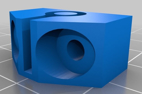
Correct, for each belt holder use 2 x M3 screws.
"Also, how are the belts held in the holders? Should I rely on the teeth inside the slot, or did you do it a different way? The reason I ask is that I can see that you have folded the belts back in your photos."
This holder are from the first design, the teeth secure the belt. I have printed and try this one first and i do not like the result, they do not secure very well the belt and you need to cut the belt very precise.
I have used a new type of holder that are better and was not in the project.
I have added the belt holder in the project and upload the stl file. Use this new ones they are better, they secure very well the belt and you do not need to make an precise cut of the belt.
When putting the belt in the holder do not forget that the teeth of the belt must be inside the curve. If you put the teeth outside the belt will not be secure.
Edited 2 time(s). Last edit at 10/05/2015 05:50AM by filipeCampos.
Sorry, only registered users may post in this forum.
