G&C Printer
Posted by filipeCampos
|
Re: G&C Printer October 05, 2015 10:10AM |
Registered: 9 years ago Posts: 893 |
Thanks Filipe, those belt holders do work well (although it's quite a task to get the belt in the slot!).
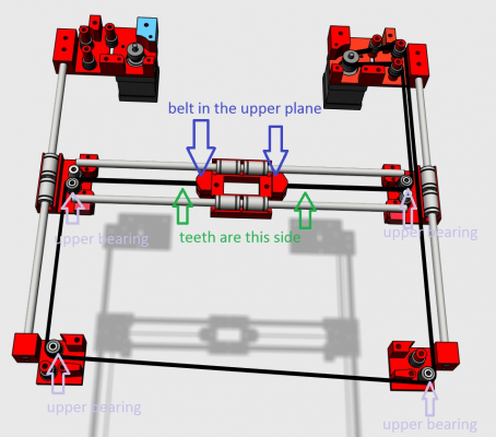
Would it be possible for you to do a drawing of the belt paths? It's very difficult to work it out from the 123D model, and I'm sure that a belt layout drawing would be very useful to anyone building this printer, not just for me.
Apart from that - I'm still busy making parts, ready for when my extrusions and their fasteners arrive (they've been shipped, according to Motedis). Then I'll be waiting for lots of parts to arrive from China...
Regards,
David
|
Re: G&C Printer October 05, 2015 01:57PM |
Registered: 8 years ago Posts: 346 |
using an drawing to explain in not easy because they are 2 belt in different planes.
I have make 2 drawing using my 3d project, one explain the lower plane and the other the upper plane. Each plane was is own belt and both belt was the exact same size.
The lower plane:
The upper plane:
I have installed both planes making the next steps:
1) I have secure and installed one side of the lower belt, At this point i have only one belt of 5 meter.
2) insert the belt in all the bearings until i reached the other side.
3) step 1 an 2 are only used to obtain the size of the belt you need. Cut the belt, but leave at least plus 10 cm.
4) remove the lower belt from the pieces and use it to cut the second belt with the same dimensions.
5) install again the lower belt. Only make the tension in step 7. The belt must be well tensioned, use to M3 screw for the tension and not the moving bearing in the x and y motor supports. The moving bearing are only used to close the loop of the 20T pulleys. before installing the belt this moving bearings must be already in place.
6) install the upper belt.
7) add tension in both belt using the m3 screw.
The installation of the belt is very important, take you time..
They must be well tension and both have the same tension. One way to get the same tension is to cut and secure both belt with the exact same dimension.
The installation of the Z axis was the more complicate to build, this because you do not have any point to use was an guideline.
|
Re: G&C Printer October 05, 2015 03:57PM |
Registered: 9 years ago Posts: 893 |
That is most excellent, Filipe! Exactly what I required.
Where is a good starting position for the idlers in the motor mounts? Should I just set it by eye to get a good wrap around the motor pulley, making sure that both sides are the same?
I have found out that my metalwork arrives tomorrow, so the build can start in earnest.
Thanks.
Edited 1 time(s). Last edit at 10/05/2015 04:04PM by David J.
Where is a good starting position for the idlers in the motor mounts? Should I just set it by eye to get a good wrap around the motor pulley, making sure that both sides are the same?
I have found out that my metalwork arrives tomorrow, so the build can start in earnest.

Thanks.
Edited 1 time(s). Last edit at 10/05/2015 04:04PM by David J.
|
Re: G&C Printer October 06, 2015 05:27AM |
Registered: 8 years ago Posts: 346 |
Hi David,
"Where is a good starting position for the idlers in the motor mounts?"
I have started by securing the belt in is holder, but if you start in the motor mounts you get the same result. Not sure what is the easy way..
"Should I just set it by eye to get a good wrap around the motor pulley, making sure that both sides are the same?"
yes.
You need to make an first tension of the belt by hand, you apply an good amount of force and make sure that the belt is well mounted in all the pulleys. Cut the 1º belt, if your are not sure of the length add a little more like 5 or 10 cm, you can remove the cm more at the end. Remove the belt and put side by side to cut the second belt. After you have cut the 2 belt, install them but only applying tension by hand, the final tension will be made using the M3 screws. You must install the belt with the most tension you can make by hand. Both belt have the same length and consequently the same number of teethes, you count the teethes that are left outside of the belt holder to obtain the same length and tension. In my case I have left 4 teethes outside in each belt holder. Finally you screw all the M3 to get the final tension and i can cut the 5 or 10 cm more you have added.
I have printed more than 100h in my printer and noticed i lost a little of the tension in the belts. After many hours of use it can be necessary to add more tension in both belts.
I getting better result with the direct extruder. Before i have some problem with tiny filament and little blobs, this problems disappear and noticed the exterior wall are more "homogeneous".
The only downside i have noticed so far is the printer sometimes shake the table.
One print i have made with the direct extruder:
Edited 4 time(s). Last edit at 10/06/2015 05:52AM by filipeCampos.
|
Re: G&C Printer October 06, 2015 08:49AM |
Registered: 9 years ago Posts: 893 |
|
Re: G&C Printer October 06, 2015 09:04AM |
Registered: 8 years ago Posts: 346 |
|
Re: G&C Printer October 06, 2015 09:25AM |
Registered: 9 years ago Posts: 893 |
I realised that I was talking rubbish! You had already specified M3 nylok nuts, so my point was irrelevant.
I found it necessary to lightly file the grooves that hold the bearings to make sure that there were no high points. Also, as I said, it's necessary to only nip the nuts tight, to avoid distortion. This made everything work nicely.
I haven't built the frame yet - I've only assembled the pieces to make sure that there no unexpected problems (like these bearings).
|
Re: G&C Printer October 08, 2015 10:00AM |
Registered: 9 years ago Posts: 893 |
Well, progress is being made... 
Everything is straight and true, and the X and Y slides are moving freely. Which is nice.
I had one or two problems though - I couldn't see what the 5mm T-nuts were for when I started, and decided that I'd work it out as I went along. Are they for the supports and bearings of the Z-carriage?
Also, looking at the Z-carriage, I can see another error in the BOM - it specifies 5 of Bracket Alu elox width 20x40, but it should be 6. This is 4 for the inside of the top 4 extrusions, and 2 for the Z carriage.
Finally, the BOM specifies 1 Bracket Alu elox 20x20, but I can't see where that fits. Any clues? UPDATE: Spotted it! it's the support for the RAMPS cooling fan.
Apart from that, Motedis left a couple of brackets out of my order, so I can't put the Z-carriage together (I'm still waiting for a few bits from China anyway).
Edited 4 time(s). Last edit at 10/08/2015 10:37AM by David J.

Everything is straight and true, and the X and Y slides are moving freely. Which is nice.
I had one or two problems though - I couldn't see what the 5mm T-nuts were for when I started, and decided that I'd work it out as I went along. Are they for the supports and bearings of the Z-carriage?
Also, looking at the Z-carriage, I can see another error in the BOM - it specifies 5 of Bracket Alu elox width 20x40, but it should be 6. This is 4 for the inside of the top 4 extrusions, and 2 for the Z carriage.
Finally, the BOM specifies 1 Bracket Alu elox 20x20, but I can't see where that fits. Any clues? UPDATE: Spotted it! it's the support for the RAMPS cooling fan.
Apart from that, Motedis left a couple of brackets out of my order, so I can't put the Z-carriage together (I'm still waiting for a few bits from China anyway).

Edited 4 time(s). Last edit at 10/08/2015 10:37AM by David J.
|
Re: G&C Printer October 08, 2015 12:41PM |
Registered: 8 years ago Posts: 346 |
Hi David,
The structure is looking good..
About the 5mm t-nuts, i brought 16 to secure the aluminium SCV12UU (need 8) and SH12A (need 8). But when i receive the SCV12UU i found is only possible to put M4 screw.
I have used 8 to secure SH12A Linear Rail Shaft and the other 8 that was for the SCV12UU was used to secure other things, like:
2 of them are used to secure the power supply in the profile 20x40.
2 to secure the filament support
1 for the board fan
1 for the relay (in your case you do not need relay)
2 for the support of the ramps board
I have brought 6 Bracket Alu elox 20x40 (4 on top and 2 for the bed structure). The bom file was only 5, it must be an typing error.
If you have only 5 because of this error, you can use 3 bracket 20x40 + 1 bracket 20x20 on the top and 2 for the bed structure. if you replace on the top one 20x40 for one 20x20 there will be no problem.
To secure the fan you can print one bracket 20x20.
I will correct the bom file.
I sorry about these errors, there are some problems i found only in the building process and i have forget to updated in the bom file. When building the printer i was like a kid with an new toy and totally forget the documentation.
Thanks you for your help to identify these problems.
Edited 5 time(s). Last edit at 10/08/2015 01:24PM by filipeCampos.
The structure is looking good..

About the 5mm t-nuts, i brought 16 to secure the aluminium SCV12UU (need 8) and SH12A (need 8). But when i receive the SCV12UU i found is only possible to put M4 screw.

I have used 8 to secure SH12A Linear Rail Shaft and the other 8 that was for the SCV12UU was used to secure other things, like:
2 of them are used to secure the power supply in the profile 20x40.
2 to secure the filament support
1 for the board fan
1 for the relay (in your case you do not need relay)
2 for the support of the ramps board
I have brought 6 Bracket Alu elox 20x40 (4 on top and 2 for the bed structure). The bom file was only 5, it must be an typing error.
If you have only 5 because of this error, you can use 3 bracket 20x40 + 1 bracket 20x20 on the top and 2 for the bed structure. if you replace on the top one 20x40 for one 20x20 there will be no problem.
To secure the fan you can print one bracket 20x20.
I will correct the bom file.
I sorry about these errors, there are some problems i found only in the building process and i have forget to updated in the bom file. When building the printer i was like a kid with an new toy and totally forget the documentation.
Thanks you for your help to identify these problems.
Edited 5 time(s). Last edit at 10/08/2015 01:24PM by filipeCampos.
|
Re: G&C Printer October 08, 2015 01:31PM |
Registered: 9 years ago Posts: 893 |
|
Re: G&C Printer October 09, 2015 06:45AM |
Registered: 8 years ago Posts: 346 |
About the M5 t-nuts, I have changed the bom file and put only 8. I think there are not very useful, m4 t-nuts do the job fine. These M5 have a big problem, it can not be inserted in the middle of the 2020 extrution like the m4.
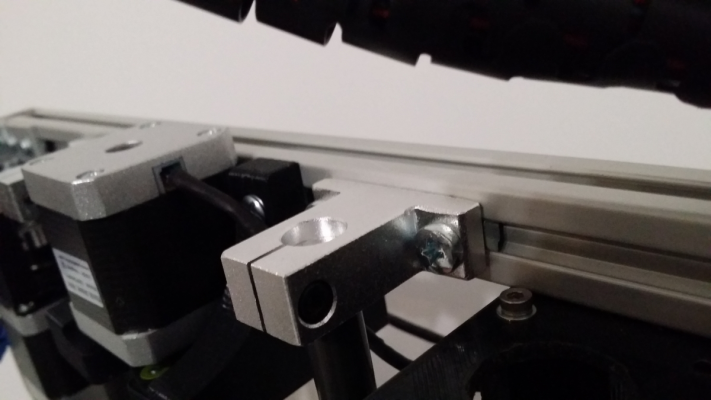
Check the next image, 8 of them are used to secure this aluminium pieces:
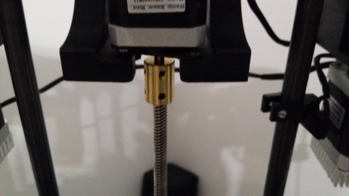
Yesterday I have upgrade the Z coupler from a flexible one to a rigid one. The rigid give a better result overall, less vibration when the z move fast.
The main problem is the coupler is supporting all the mass of the print table and using an flexible give some vibration.
One solution i was trying to implement is to flip the Z screw, put the Z motor in the bottom of the printer. But if this is done there will be print volume lost, do you have any suggestion?
Edited 1 time(s). Last edit at 10/09/2015 06:46AM by filipeCampos.
|
Re: G&C Printer October 09, 2015 07:41AM |
Registered: 9 years ago Posts: 893 |
I think that I will probably try to use the M4 t-nuts to start with - if they don't work well then maybe I'll fit the M5 ones. I'll find out when the supports arrive from China...
As for the Z motor - mechanically it probably makes sense to have the motor underneath, and would be a lot safer if vibration shakes the coupler's screws loose. It may not work properly after they come loose, but at least it wouldn't crash down on the base of the frame. Also the vibration damper would have an easier life (yes, I've fitted them as well), being in compression rather than tension.
Looking at my frame, I don't think you would lose a lot of build height - maybe just a centimeter or three. This is especially true if you design new mounts to keep the motor low, rather than re-using the original ones. Maybe a mount fitted across the 2 lower extrusions, with a fixing platform for the motor?
One quick question - what is the spacing between the vertical 12mm rods on your printer? I might as well get mine set to the same measurement.
Edited 2 time(s). Last edit at 10/09/2015 07:47AM by David J.
|
Re: G&C Printer October 09, 2015 08:49AM |
Registered: 8 years ago Posts: 346 |
"what is the spacing between the vertical 12mm rods on your printer? I might as well get mine set to the same measurement."
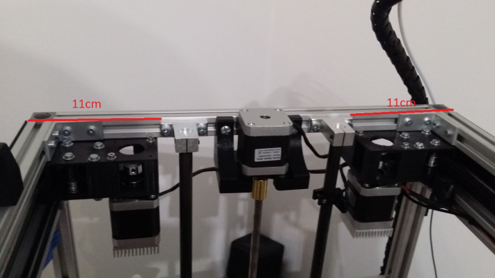
This spacing was made by personal choice, I will explain: The 2 x 12mm rods are 50cm lenght and the printer is 52cm, If the bottom and top 2020 aluminium bar are spaced by +/- 47 cm the fit will be perfect and there will be no spacing. In my case i have separate a little more the 2020 bares to gain a little more print volume in the Z axis. I have put both 12mm rods end in the middle of all the SH12A to obtain the maximum volume print possible and having the rods well secure.
But was i say, is only an personal choice and in not the way it is in the design.
After i have build the printer i see that lowering the bottom 2020 bar to gain more volume space was an error. If this lower 2020 bar was 1 cm upper the print volume will be almost the same.
Resuming: do not make the same error, simply adjust the lower bar to have an perfect fit of the 12mm rods in the SH12A.
When i have some time i will try to design an new Z motor mount to put the motor at the bottom.
Edited 1 time(s). Last edit at 10/09/2015 09:01AM by filipeCampos.
|
Re: G&C Printer October 09, 2015 09:03AM |
Registered: 10 years ago Posts: 344 |
|
Re: G&C Printer October 09, 2015 09:39AM |
Registered: 8 years ago Posts: 346 |
|
Re: G&C Printer October 09, 2015 11:18AM |
Registered: 9 years ago Posts: 893 |
Sorry Filipe, that's not what I meant! 
What I intended to ask was, how far apart are the two 12mm rods?
And gforce1's comment made me think of a solution - a metal collar with an 8mm hole in the middle, and 2 grub screws to hold it onto the shaft would stop the drive screw dropping. Ideally a thrust bearing would be the best thing to take the side load (I'll do some research to see if there's a thrust bearing of a similar size to the 608).
Research done: here's the sort of thing I meant - ebay bearing
Personally, I think putting the motor at the bottom would be a lot simpler...
Edited 2 time(s). Last edit at 10/09/2015 11:27AM by David J.
|
Re: G&C Printer October 09, 2015 01:06PM |
Registered: 8 years ago Posts: 346 |
"how far apart are the two 12mm rods?"
When i get home i will give you the dimension i have in my printer, but you do not need to use the exact same ones.
For me the Z axis was a pain in the *** to mount correctly, because the four SH12A and four SCV12UU can be placed anywhere in the 2020 bars.
This is the steps i have used, i think them can help you.
I have installed the Z screw only after the bed structure.
1) first mount and secure the top SH12A very close of the pla printed x and y mount motors. have them at the same distance of the mount motors, this way they will be centered in the printer.
2) install the SCV12UU in the bed structure, they will be correctly adjusted/secured after.
3) install the SH12A at bottom, 12mm rods and bed structure without the Z screw.
4) put the bed structure at the top of the printer and put the bed leveled, secure the SCV12UU.
5) put the bed structure at the bottom of the printer and secure the bottom SH12A. verify if the SH12A are the same distance, centered and the bed is leveled.
6) repeat 4 and 5 util everything is well secured and the bed structure move freely without any friction. Only check the level of the bed in the x axis.
now i understand the use of the "thrust bearing". Like you i prefer to put the Z motor at the bottom, is more easy and clean solution.
The possibility to hide the z motor in the bottom will look better this way.
|
Re: G&C Printer October 09, 2015 01:18PM |
Registered: 9 years ago Posts: 893 |
Quote
filipeCampos
now i understand the use of the "thrust bearing". Like you i prefer to put the Z motor at the bottom, is more easy and clean solution.
The possibility to hide the z motor in the bottom will look better this way.
I agree - and you can move the shaft's bottom bearing up to the top without needing to modify it in any way.
|
Re: G&C Printer October 09, 2015 01:44PM |
Registered: 9 years ago Posts: 5 |
I'm interested in this design. What exactly is different with this and Jand's design? I have a 500x500x500 frame already that I was planning to use. With the increased size I was wanting to 10mm rods instead of 8mm, but it's actually easier to get the igus for 12mm rods. Would it take much to adapt the current design to those specifications?
BTW, Just as an observation and experienced frustration with other threads, the chit chat back and forth makes it difficult for people to enter this project later on. Possibly exchanging private messages or personal emails and updating the thread accordingly with information that would be helpful to others would make it easier for new people to follow this thread.
BTW, Just as an observation and experienced frustration with other threads, the chit chat back and forth makes it difficult for people to enter this project later on. Possibly exchanging private messages or personal emails and updating the thread accordingly with information that would be helpful to others would make it easier for new people to follow this thread.
|
Re: G&C Printer October 09, 2015 02:13PM |
Registered: 9 years ago Posts: 893 |
|
Re: G&C Printer October 09, 2015 02:14PM |
Registered: 8 years ago Posts: 346 |
jand´s design? can you give me the link of this design?
All the dimensions of this printer was set to use an cheap and standard 20x20cm heated bed. The frame of this printer is 400x400x520, with an 500x500x500 frame you can/must use an 30x30 bed, the print volume will be 300x300x250.
The 10mm rods was already something i was planning to do when i will design the dual extruder, but only in the Y axis.
These modifications are easy to made, but it will take some time. If you are interested in the design you can take this project at starting point an make this modification. I will gladly help you in the process.
|
Re: G&C Printer October 09, 2015 02:18PM |
Registered: 9 years ago Posts: 5 |
Quote
jand´s design? can you give me the link of this design?
It's the link you have in your thingiverse page. [github.com]
|
Re: G&C Printer October 09, 2015 03:05PM |
Registered: 8 years ago Posts: 346 |
This design and jand design use the same corexy mechanism, and there are the same because both used the same project was source. But this was already explained in my first post, the corexy mechanism is not my design. But i think it the only thing they share, i already see this design before and there are pieces i have obtaind from this repository.
This project is diferent from other because my main goal was to use cheap and common hardware like the 20x20 bed, the z axis was build using mostly cheap aluminium hardware. The design of the main structure was made to be rigid and easy add panels to hide and protect electronics and corexy mechanism.
About the chit chat, this is an forum, is objectif is to talk about the printer and not be an static repository of information. I have already lot of posts shared with David and was result it was found several problems and missing information that was corrected in the thinginverse web site.
A good solution it will be create and wiki page to put the information resulting of all this chit chat...
Edited 3 time(s). Last edit at 10/09/2015 03:26PM by filipeCampos.
|
Re: G&C Printer October 09, 2015 05:00PM |
Registered: 8 years ago Posts: 346 |
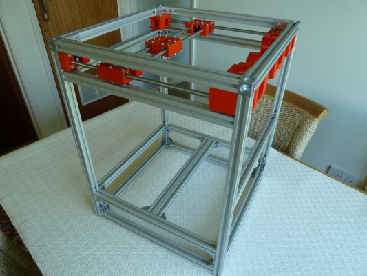
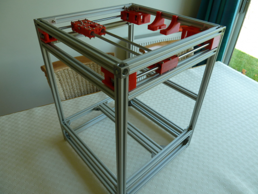
the dimension:
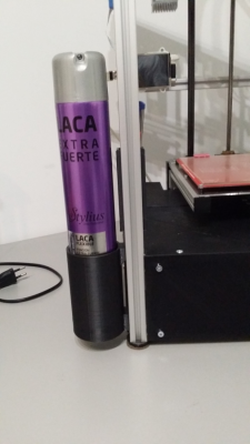
added simple hair spray holder:
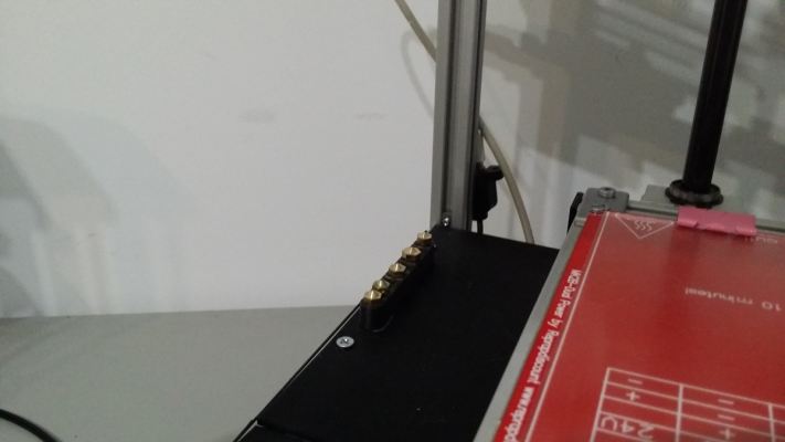
added nozzles holder:
Used an nozzle holder i found in thingiverse and glued in one of the panel
added simple hair spray holder:
added nozzles holder:
Used an nozzle holder i found in thingiverse and glued in one of the panel
|
Re: G&C Printer October 09, 2015 05:28PM |
Registered: 9 years ago Posts: 893 |
|
Re: G&C Printer October 10, 2015 05:46AM |
Registered: 8 years ago Posts: 346 |
|
Re: G&C Printer October 10, 2015 06:48AM |
Registered: 9 years ago Posts: 893 |
|
Re: G&C Printer October 11, 2015 05:28AM |
Registered: 8 years ago Posts: 346 |
Hi David,
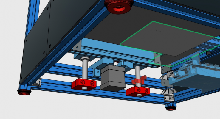
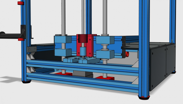
Yesterday i have successfully moved the motor to the bottom.
But i have found several problems in the process.
1 - in this design the coupler is very close of the pla piece that connects to bed, i found that the original dimensions was off 2 mm. Only the 3 print was worked corretly. This problem do no happen in the other design because the z screw is allway 10 cm far of the coupler.
2 - lost 6mm of print volume. Now i have 26,4 cm.
3 - the pieces with the bearings can not be installed. But i found in this design there is no vibrations problems, so no need to install.
In pla piece of the bed i have give room to support the rigid and flexible coupler. When i have more time i will upload these new pieces, they are 3 in total. The pieces of the bed need to have the dimensions very precise. My dimensions can not be the exast same for your printer. I will sugest you first print the same and try, if you found is not exast i will help you and make a new one for your printer.
Edited 4 time(s). Last edit at 10/11/2015 05:39AM by filipeCampos.
|
Re: G&C Printer October 11, 2015 06:27AM |
Registered: 9 years ago Posts: 893 |
Filipe,
That looks good. I look forward to trying it on my printer.
As for the problems:
1. I was wondering if you would have issues with clearance for the coupler! I'm glad you sorted it.
2. Not a problem for me - I rarely make anything tall, and my Prusa can only manage 20cm (and that's pushing it) so 26.4cm is good for me.
3. I was wondering why the screw was short of the top rail - then I remembered that the Z motor was mounted slightly below the rail in the original design.
How close does the nut get to the top of the screw when the bed is at maximim height?
|
Re: G&C Printer October 11, 2015 02:04PM |
Registered: 8 years ago Posts: 346 |
"How close does the nut get to the top of the screw when the bed is at maximim height?"
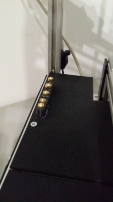
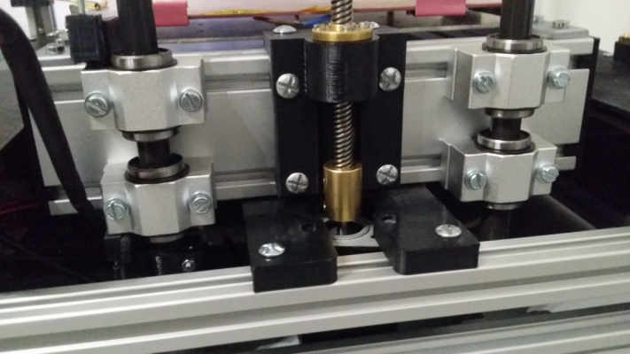
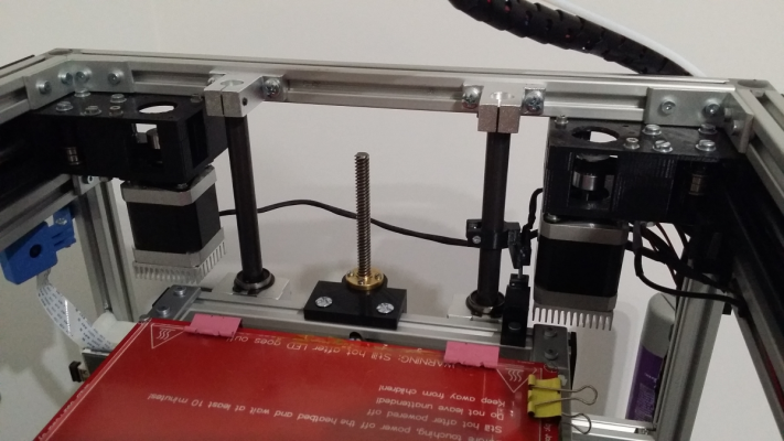
The two photos are both at the max and min of Z.
Uploaded an youtube videos to show the Z axis working. First is homing and them goes from position 0 to 26,4cm at fast speed.
[www.youtube.com]
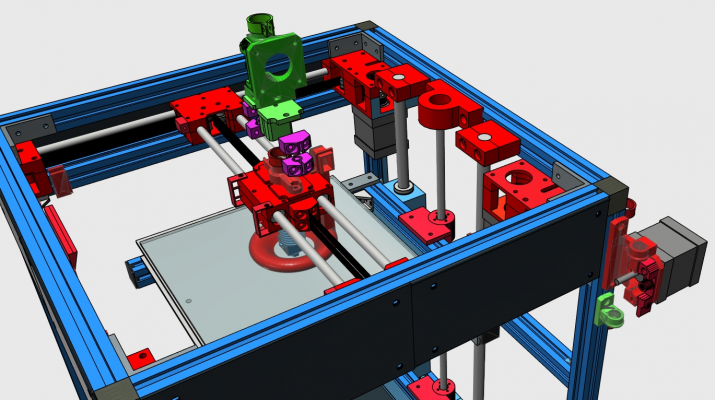
I have uploaded the new version of the 3d project and removed one 608 bearing from the bom file.
Edited 1 time(s). Last edit at 10/11/2015 02:21PM by filipeCampos.
Sorry, only registered users may post in this forum.

