G&C Printer
Posted by filipeCampos
|
Re: G&C Printer March 26, 2016 12:09PM |
Registered: 8 years ago Posts: 9 |
Tightening/loosening yes. Vref - not sure what you mean. Running at 90 steps per mm at 2 amps currently (2 amps being the rated current of my extruder stepper motor). Reckon I'm going to have to lower that though as the thing is running very hot and loos to have distorted the extruder mounting already. Hot and heavy is a bad combo for stepper motor supported by plastic mounts in my experience!
|
Re: G&C Printer March 26, 2016 12:17PM |
Registered: 8 years ago Posts: 9 |
Tightening/loosening yes. Vref - not sure what you mean. Running at 90 steps per mm at 2 amps currently (2 amps being the rated current of my extruder stepper motor). Reckon I'm going to have to lower that though as the thing is running very hot and looks to have distorted the extruder mounting already. Hot and heavy is a bad combo for stepper motor supported by plastic mounts in my experience!
|
Re: G&C Printer March 26, 2016 04:07PM |
Registered: 9 years ago Posts: 29 |
Vref is the maximum current setting on a ramps or compatible board (using a potmeter), a MKS Sbase doesn't have Vref potmeters but the max current is set via the config.txt file.
My extruder setting is 280 steps/mm on 1/32 micro stepping (had the extruder running yesterday and did a calibration test). The extruder is a Chinese MK8 contraption.
My extruder setting is 280 steps/mm on 1/32 micro stepping (had the extruder running yesterday and did a calibration test). The extruder is a Chinese MK8 contraption.
|
Re: G&C Printer March 26, 2016 04:44PM |
Registered: 8 years ago Posts: 9 |
Quote
Nosmo
Vref is the maximum current setting on a ramps or compatible board (using a potmeter), a MKS Sbase doesn't have Vref potmeters but the max current is set via the config.txt file.
My extruder setting is 280 steps/mm on 1/32 micro stepping (had the extruder running yesterday and did a calibration test). The extruder is a Chinese MK8 contraption.
Are you running direct drive or Bowden? If direct drive, how are you mounting the extruder to the carriage? My modelling skills aren't up to much, so I'd love a copy of your mount if you're running direct drive.
I'm currently using 1/16 stepping, do I just double all my steps per mm if I move to 1/32? There's a jumper on the board to switch to 1/32, correct?
|
Re: G&C Printer March 26, 2016 05:17PM |
Registered: 9 years ago Posts: 29 |
I'm using a Bowden setup sorry!
Yes and yes, just set the jumper to 1/32 and double the steps/mm for all stepper motors.
Edited 1 time(s). Last edit at 03/26/2016 05:18PM by Nosmo.
Quote
simon_smithson
I'm currently using 1/16 stepping, do I just double all my steps per mm if I move to 1/32? There's a jumper on the board to switch to 1/32, correct?
Yes and yes, just set the jumper to 1/32 and double the steps/mm for all stepper motors.
Edited 1 time(s). Last edit at 03/26/2016 05:18PM by Nosmo.
|
Re: G&C Printer March 28, 2016 06:24AM |
Registered: 8 years ago Posts: 346 |
Quote
simon_smithson
Biggest issue I'm currently having is with the extruder. I'm currently using a single direct drive. It seems to go wildly from under to over extruding. Not entirely convinced that having the print spool at the bottom of the machine and a length of PTFE tubing is the best approach for me, so I might shift the filament holder to the top of the machine.
Hi,
Sure, you can put the spool on top and not use the 50cm ptfe tube. The only important part is to have the +/- 10cm of ptfe tube that goes from the extruder up to the nozzle of the hotend.
I read you a running you extruder motor at 2A, this is way to much.. the motor must run without going more of 50ºC. The situation you are reporting is not normal, you have some jamming problem or something like this.
|
Prints offset after around layer 11 April 05, 2016 04:01PM |
Registered: 8 years ago Posts: 1 |
|
Re: Prints offset after around layer 11 April 06, 2016 02:06AM |
Registered: 9 years ago Posts: 31 |
Quote
ddragon
Not sure what is causing this. But after around layer 11 the printer starts to print down to the left (off set)... I changed the Stepper_High_Delay to 2... still doing it. I'm running pretty basic setup... Ramp 1.4. I have a smart control on it... would this do it?
My guess would be that your stepper driver current is too high and overheating and possibly shutting down for a few seconds, or possibly just the opposite and it is skipping steps due to lack of stepper driver current.
-os3dp
|
Re: Prints offset after around layer 11 April 06, 2016 03:19AM |
Registered: 8 years ago Posts: 346 |
|
Re: G&C Printer April 27, 2016 06:01PM |
Registered: 8 years ago Posts: 11 |
filipe, have you seen E3D's new Titan extruder? I'm wondering what kind of changes I'd have to make to the carriage to accommodate it in a dual-extruder config.
FYI, I'm getting close to finishing, but miscounted the bearings I purchased and am waiting for those to come in. Then it should be just a matter of running the belts, wiring everything up and seeing what happens!
FYI, I'm getting close to finishing, but miscounted the bearings I purchased and am waiting for those to come in. Then it should be just a matter of running the belts, wiring everything up and seeing what happens!

|
Re: G&C Printer April 27, 2016 06:34PM |
Registered: 8 years ago Posts: 346 |
the new e3d appears to be a very good extruder, and using small motor can be very light, but they are new and way to expensive. i pretty sure in no time the price will drop and start to appear printed version.
about the changes... i need the get the dimension off the base and where are the fixing holes to see the best way to install them directly on the carriage.
the printer looks great. what is the print volume?
about the changes... i need the get the dimension off the base and where are the fixing holes to see the best way to install them directly on the carriage.
the printer looks great. what is the print volume?
|
Re: G&C Printer April 27, 2016 06:39PM |
Registered: 8 years ago Posts: 11 |
Quote
filipeCampos
the new e3d appears to be a very good extruder, and using small motor can be very light, but they are new and way to expensive. i pretty sure in no time the price will drop and start to appear printed version.
about the changes... i need the get the dimension off the base and where are the fixing holes to see the best way to install them directly on the carriage.
the printer looks great. what is the print volume?
I'm going to get this working with the dual direct-drives w/e3D Lite6s, and then probably swap to the Titans sometime this summer. I should be able to make any mods in 123d and post my results, it just may take a bit
 .
.this is going to be right around 30cm^3. It seems stable enough with the 8mm leadscrew and 12mm smooth rods. We'll see once I get it moving
|
Re: G&C Printer April 28, 2016 02:58AM |
Registered: 8 years ago Posts: 9 |
Funnily enough my Titan extruder arrived yesterday. There are no mounting holes on the extruder itself, instead you mount via a printed plate sandwiched between the extruder and stepper. My current plan is not to use the hole in the middle of the carriage as, by default, the extruder wants the hotend directly interfaced with the extruder. I've also had endless issues with the gap between extruder and hotend in the standard design. So I'm going to move the limit switches to the back of the carriage and mount the extruder and hotend such that the hotend hangs off the front of the carriage.
This is going to mean that the bed will need to be much higher, and moved forwards from its current position.
No idea if it's going to work, but the current setup doesn't work for me either.
Edited 1 time(s). Last edit at 04/28/2016 04:17AM by simon_smithson.
This is going to mean that the bed will need to be much higher, and moved forwards from its current position.
No idea if it's going to work, but the current setup doesn't work for me either.
Edited 1 time(s). Last edit at 04/28/2016 04:17AM by simon_smithson.
|
Re: G&C Printer April 28, 2016 04:55AM |
Registered: 8 years ago Posts: 346 |
This extruder is really something worth to check, in my case if i could use two of these Titans instead of my mk8 i could remove more of 400gr from the carriage...
On possible solution is to design a top plate (the plate goes on top of the carriage) that have two end format of a E3D V6 hotend, then you run two ptfe tube that goes from the hotend to the extruder, the tube pass in middle of the carriage. I have a very similar setup and work just fine, is not a direct setup, but almost the same.. my two ptfe tubes have less of 10cm. The only problem i see is the check if they sell right and left hand Titans extruder, so far i only see right hand.
Quote
simon_smithson
There are no mounting holes on the extruder itself, instead you mount via a printed plate sandwiched between the extruder and stepper.
On possible solution is to design a top plate (the plate goes on top of the carriage) that have two end format of a E3D V6 hotend, then you run two ptfe tube that goes from the hotend to the extruder, the tube pass in middle of the carriage. I have a very similar setup and work just fine, is not a direct setup, but almost the same.. my two ptfe tubes have less of 10cm. The only problem i see is the check if they sell right and left hand Titans extruder, so far i only see right hand.
can be a solution, but you will loss print volume on the y axis and one of the extruder will be difficult to service.Quote
simon_smithson
So I'm going to move the limit switches to the back of the carriage and mount the extruder and hotend such that the hotend hangs off the front of the carriage.
|
Re: G&C Printer April 28, 2016 06:36AM |
Registered: 8 years ago Posts: 9 |
As far as I'm aware the extruders are only right handed.
Ironically the printed bracket that they sell with the extruder, or that you can download and print yourself has a bolt pattern that is almost IDENTICAL to that on the top of the carriage. It's even exactly the same width. Very strange.
I've just mocked up the idea of hanging the hot end off the front of the carriage and it looks good. The difference in Z is not as marked as I thought it might be and I might even get away with leaving the limit switches in their original location (assuming they don't melt...).
I'm only running a single extruder currently, so a dual extruder setup is likely a whole different kettle of fish.
My problems have all been extruder/hot end related. I've thus far had 5 different extruders, with about 4 different hobbed gears, both bowden and direct setups, two different hot-ends, 3 different stepper motors and both actively and passively cooled my control board. Not to mention an array of different steps per mm and extruder stepper current settings. All end up with the same issue; the extruder stepper skipping. Often I can get a good 10mm or so into a print before this starts happening to the point where the print fails. The clog always seems to occur in the ptfe tube between the extruder and the hot end, though I may be wrong about that (I've replaced this a good ten times by the way!).
I'm desperately hoping it's not a problem with the control board dropping current after a period of operation - hence the new 120mm fan blowing cold air onto it. It could also be a dodgy power supply, though I'm not seeing any drop in hotend temperatures that would indicate that. I don't really want to start wiring multimeters into the stepper circuit, though it may come to that.
I'm desperately hoping that altering the hotend/extruder setup will resolve this as I'm getting really fed up!
|
Re: G&C Printer May 01, 2016 06:44PM |
Registered: 8 years ago Posts: 33 |
@filipeCampos
I've spent a few hours and read thorough this thread, I'm still undecided what printer should be my first.
But I really like your design for several reasons, It look very rigid and robust.
The printed parts seem simple to print (I hope I can convince the guy at work who's responsible for the Zyyx printer we have to let me use it. And with NO experience printing trying complex prints with supports and what not is not ideal.)
And several other reasons, but at the moment I'm sort of cross referencing it to for example the Vulsanus V1 and other sources for part to see if I could get the cost down abit.
But anyway I have a few questions.
1. The 20X40 Extrusion in the bottom, what's its purpose? I can figure out if it's there to stiffen up the frame or just to hang the PSU of?
2. What was the reason for choosing the B-slot 6mm extrusion and not the I-slot 5mm? (Asking because the 5mm seems more common)
3. In the BOM you mention replacing you 30A PSU for a 25 or 20, excuse my ignorance but why?
4. Whats the 40A relay for?
Thanks.
|
Re: G&C Printer May 01, 2016 07:13PM |
Registered: 8 years ago Posts: 346 |
hi,
still not decided...
1- hand psu, fan cool the board, secure cables, stiffen more the frame and allow to put 4 bottom panel. Overall is pratical, but not vital.
2- i do not remenber, maybe because of the price or tnuts compability
3- because 30A for a 20x20 bed is overkill. 20 or 25 is cheaper and will do the job. note: talking about 12v power supply and not 24v. my printer consume at max 115w (only when start heating), but when the temp' s are achieved the consume is between 30 to 40w. easy to see 30A is 3 times what the printer consume when is at max.
4- in case you go with a cheap board like ramps 1.4, is better to put a external relay and not use the bed direlty connected to the board. the ramps can overheat if you do not use the relay. with a good board there is no need of this relay. you need to check the max Amp the board can have for the bed and if you can avoid the relay, it make a bang bang noise.
|
Re: G&C Printer May 01, 2016 07:23PM |
Registered: 8 years ago Posts: 11 |
Quote
filipeCampos
4- in case you go with a cheap board like ramps 1.4, is better to put a external relay and not use the bed direlty connected to the board. the ramps can overheat if you do not use the relay. with a good board there is no need of this relay. you need to check the max Amp the board can have for the bed and if you can avoid the relay, it make a bang bang noise.
Dumb question but do you have a wiring diagram where the relay goes? even something crappy whipped up on MS Paint would help me

|
Re: G&C Printer May 01, 2016 07:36PM |
Registered: 8 years ago Posts: 346 |
Quote
critter42
Quote
filipeCampos
4- in case you go with a cheap board like ramps 1.4, is better to put a external relay and not use the bed direlty connected to the board. the ramps can overheat if you do not use the relay. with a good board there is no need of this relay. you need to check the max Amp the board can have for the bed and if you can avoid the relay, it make a bang bang noise.
Dumb question but do you have a wiring diagram where the relay goes? even something crappy whipped up on MS Paint would help me
[www.youtube.com]
use the pin numbers indicate in the video...
Edited 1 time(s). Last edit at 05/01/2016 07:39PM by filipeCampos.
|
Re: G&C Printer May 02, 2016 04:53AM |
Registered: 8 years ago Posts: 346 |
@Amoniak
About the choosing of your printer. I know money is a big issue and your are trying to go with a printer that have the best value for the buck. Before building this printer i was too looking for a printer on the cheap side. I decided to build my own because all the model (not the expensive ones) have one big problem to my eyes; the main frame... The main advantage of this model is the main frame (rigidity, organization, easy to enclose). For some people is structure is overkill, but not to me. It will allow to upgrade without the need to modify or have concern about the structure.
You have already read from several people to not go cheap on some parts and they are correct, for example if you choose a bad hotend it can give you jamming problem that are almost impossible to solve. the main structure is one of these components in my "not to go cheap" list. But the printer will never goes to the very good printer because of is x,y axis, still use of 8mm rods, lots of printed parts. But i already working on a new version to solve this and it will use the exact same frame.
If you go with this printer in my opinion is a great choose, but it will not be less of 450€... is simply out of the less 400€ budget. Most of the cost difference is related with the frame. You can not have a great printer with a weak rigidity frame.
Edited 1 time(s). Last edit at 05/02/2016 05:01AM by filipeCampos.
|
Re: G&C Printer May 02, 2016 05:53AM |
Registered: 8 years ago Posts: 12 |
Quote
filipeCampos
@Amoniak
About the choosing of your printer. I know money is a big issue and your are trying to go with a printer that have the best value for the buck. Before building this printer i was too looking for a printer on the cheap side. I decided to build my own because all the model (not the expensive ones) have one big problem to my eyes; the main frame... The main advantage of this model is the main frame (rigidity, organization, easy to enclose). For some people is structure is overkill, but not to me. It will allow to upgrade without the need to modify or have concern about the structure.
You have already read from several people to not go cheap on some parts and they are correct, for example if you choose a bad hotend it can give you jamming problem that are almost impossible to solve. the main structure is one of these components in my "not to go cheap" list. But the printer will never goes to the very good printer because of is x,y axis, still use of 8mm rods, lots of printed parts. But i already working on a new version to solve this and it will use the exact same frame.
If you go with this printer in my opinion is a great choose, but it will not be less of 450€... is simply out of the less 400€ budget. Most of the cost difference is related with the frame. You can not have a great printer with a weak rigidity frame.
You have built a great printer, but I think that it can be done much cheaper.
Your basic BOM is 466€.
100 t-nuts 21,41€ - $6 ali/ebay
100 M4x8 14,28 - $6 alie/ebay
------
25€ savings
4 x cube connector - 14,8€
8 x Connector plate 20x40 - 10,56€
3 x Bracket 20x20 B-type slot 6 with screws (10 units) - 24,99€
T-nut heavy duty steel B-Type slot 6 (M5) (8 units) - 2,25€
Inner bracket 20 steel B-Type slot 6 (16 units) - 7,44€
6 x Bracket Alu elox width 20x40 - 9,84€
Bracket Alu elox width 20x20 - 1,06€
-------
70,94€
Do you really need 71€ just for frame connectors?
digital_dentist built his printer with standard connectors with two drilled access holes, and he said that two holes don't affect frame rigidity.
So it is possible to use 15€ worth of standard connectors with some tapping/drilling, and that's 56€ savings.
mk2 aluminium plate - 11€
Heated Bed glass 200x200x3mm (Borosilicate) - 15,72€
11€ for plate that holds 4 bolts/springs is to much, it can be done in much cheaper way, and borosilicate glass is overkill.
So, final BOM can look like this:
466-25-56-11-16 = 358€
|
Re: G&C Printer May 02, 2016 05:57AM |
Registered: 8 years ago Posts: 11 |
One of the reasons I selected G&C was because it let me reuse a lot of the parts I already had from when I attempted a Kossel variant. This made what I had to lay out to get the other parts (especially since I was going to 24v and 300mm^3 for the build volume) much less than someone starting from scratch.
|
Re: G&C Printer May 02, 2016 06:23AM |
Registered: 8 years ago Posts: 346 |
Quote
ivo95
You have built a great printer, but I think that it can be done much cheaper.
Your basic BOM is 466€.
100 t-nuts 21,41€ - $6 ali/ebay
100 M4x8 14,28 - $6 alie/ebay
------
25€ savings
4 x cube connector - 14,8€
8 x Connector plate 20x40 - 10,56€
3 x Bracket 20x20 B-type slot 6 with screws (10 units) - 24,99€
T-nut heavy duty steel B-Type slot 6 (M5) (8 units) - 2,25€
Inner bracket 20 steel B-Type slot 6 (16 units) - 7,44€
6 x Bracket Alu elox width 20x40 - 9,84€
Bracket Alu elox width 20x20 - 1,06€
-------
70,94€
Do you really need 71€ just for frame connectors?
digital_dentist built his printer with standard connectors with two drilled access holes, and he said that two holes don't affect frame rigidity.
So it is possible to use 15€ worth of standard connectors with some tapping/drilling, and that's 56€ savings.
mk2 aluminium plate - 11€
Heated Bed glass 200x200x3mm (Borosilicate) - 15,72€
11€ for plate that holds 4 bolts/springs is to much, it can be done in much cheaper way, and borosilicate glass is overkill.
So, final BOM can look like this:
466-25-56-11-16 = 358€
yes, your are right. It is possible to reduce the cost, buying on ebay the t-nuts and replace/remove some of the connectors. BUT.. all this connectors allow the printer to be easy to build, allow to make future changes in the positions of the 2020 aluminium bars. Replacing the connectors with hole will work, but you have almost zero margin for errors and you get a frame that can not be changed.
is a trade-off between cost and easy building/future upgrades...
the mk2 aluminium plate i think is important to make the arms of the bed solid. It could be used directly the mk2 bed to do this job, but the heat will be propagate to the bed structure and this is bad.
"11€ for plate that holds 4 bolts/springs is to much, it can be done in much cheaper way, and borosilicate glass is overkill."
please give me more info about how you will have this done?
But there are some hardwar in the bom file that really need to be changed to reduce the total cost of the printer, but i do not have the time to do again this type of work.
Edited 1 time(s). Last edit at 05/02/2016 06:57AM by filipeCampos.
|
Re: G&C Printer May 02, 2016 07:41AM |
Registered: 8 years ago Posts: 33 |
@filipeCampos
Thanks, I value yours and others opinion and its starting to catch on.
I went into this with a strict budget simply because I know how easy it is to just stretch it a little, then a little more and so on (I've already done it lol).
But at the same time I do not want to spend time and money for something I already know is flawed. And I've found out that is a difficult balance.
When I first started I was dead set to build a Prusa i3 wood box frame, then P3Steel, then a Corexy and so on.
Simply because when I start to research a design I find these irritating "flaws", like the Z carriage on the SmartCoreRap etc that I would have to fix anyway.
I really like your design of the G&C for the exact same reasons you mention, it does not seems to have the "flaws" I've seen on other designs.
I just have to build a budget case for my self to see if I can manage it, and what options there are. I think as ivo95 mentions I could slim it down a bit without sacrificing to much, well see.
In the end, one of the biggest obstacles is how to acquire the printed parts. Which I'm still trying to figure out.
|
Re: G&C Printer May 02, 2016 07:59AM |
Registered: 8 years ago Posts: 12 |
Quote
filipeCampos
the mk2 aluminium plate i think is important to make the arms of the bed solid. It could be used directly the mk2 bed to do this job, but the heat will be propagate to the bed structure and this is bad.
"11€ for plate that holds 4 bolts/springs is to much, it can be done in much cheaper way, and borosilicate glass is overkill."
please give me more info about how you will have this done?
220x80x4mm alu plate is 2,67€ @ doldmechatronik. Cut two stripes, drill 4 holes and you have even better support and you saved 8€ if you want to do some cutting/drilling.
BTW do you think that 300x200mm bed size is doable with your design? (12mm rods + 4xSCV12UU holding the bed).
Edited 1 time(s). Last edit at 05/02/2016 08:00AM by ivo95.
|
Re: G&C Printer May 02, 2016 08:08AM |
Registered: 8 years ago Posts: 11 |
Quote
ivo95
BTW do you think that 300x200mm bed size is doable with your design? (12mm rods + 4xSCV12UU holding the bed).
I'm doing 300x300 on 12mm rods and 8mm leadscrew and it's rock solid (my plate is a 300mm plate salvaged from a Lulzbot Taz). I did have to increase the length of the x/y smooth rod and the extrusion pieces of the frame. And of course I screwed up those lengths initially because my American brain can't apparently convert efficiently from cm to mm
FYI, I started a blog (was a school assignment, but I'm keeping it going after the semester is up) that includes a build log for this printer: http://3dprintmemphis.space
Edited 1 time(s). Last edit at 05/02/2016 08:28AM by critter42.
|
Re: G&C Printer May 02, 2016 09:02AM |
Registered: 8 years ago Posts: 346 |
looks to be a good solution.Quote
ivo95
220x80x4mm alu plate is 2,67€ @ doldmechatronik. Cut two stripes, drill 4 holes and you have even better support and you saved 8€ if you want to do some cutting/drilling.
I only have experience with a 20x20cm bed and is just work. With this bed size i can guaranty you only need to setup once or when you change the hotend nozzle.Quote
ivo95
BTW do you think that 300x200mm bed size is doable with your design? (12mm rods + 4xSCV12UU holding the bed).
I only print with pla, i have configured my slider to put the temperature of the bed in the first layer at 70ºC degree e the next ones to 50ºC. The first layer is always perfect on all the 20x20 cm of the bed (not using any type of auto leveling). by the way, auto leveling is a software trick to solve a mechanical problem. For a bigger bed (30x30 or 20x30) i you suggest to go with 14mm rods only to be sure. critter42 was a 30x30 version build with the 12mm rods, but it will only be sure it work after done some tall prints (15cm or more on the z).
|
Re: G&C Printer May 02, 2016 12:03PM |
Registered: 8 years ago Posts: 12 |
Quote
filipeCampos
I only have experience with a 20x20cm bed and is just work. With this bed size i can guaranty you only need to setup once or when you change the hotend nozzle.
I only print with pla, i have configured my slider to put the temperature of the bed in the first layer at 70ºC degree e the next ones to 50ºC. The first layer is always perfect on all the 20x20 cm of the bed (not using any type of auto leveling). by the way, auto leveling is a software trick to solve a mechanical problem. For a bigger bed (30x30 or 20x30) i you suggest to go with 14mm rods only to be sure. critter42 was a 30x30 version build with the 12mm rods, but it will only be sure it work after done some tall prints (15cm or more on the z).
30x30 bed is huge, it's 50% bigger then 20x30.
I was worried about wobble and not sagging, and since critter42 said that his bed is rock solid, 12mm is probably enough.
He doesn't have to print so tall to see if there are any problems, since they should be most obvious in the middle of the rods, but i really doubt that there are any. We are using short rods, and 4 bearings, so any load is distributed on larger area.
Edited 1 time(s). Last edit at 05/02/2016 12:17PM by ivo95.
|
Re: G&C Printer May 02, 2016 01:07PM |
Registered: 8 years ago Posts: 346 |
It will probably by fine, but not with 12mm aluminium rods. I no time the rods will have wear and lose precision.
But i think the rods have is days counted, at the moment you can buy on ebay linear guide rails pretty cheap and the difference in cost do not justify to continue with the rods solution.
The use of this rail has a big advantage in relation to the rods, you can install them directly on the 2020 aluminium. If the main structure is well build, you get automatically a precise linear movement (no need to adjust like is done on the rods). For exemple if you by the 2020 bars already cuted, is almost 100% guaranty you can easy build a precise printer with no need to have great skills.
The rail have a very low profile (great for the bed movement), it allow to reduce the printer volume for the same print volume.
At the moment i starting the design a new version of this printer that will use two 9mm rails for the y axis and one 12mm rail for the x. The structure and bed will be the same, i will simply remove my actual corexy mechanism and replace with the new one. The main problem of this new version it will be probably necessary to have access to a cnc to cut 3 to 5 aluminium pieces.
|
Re: G&C Printer May 03, 2016 06:35PM |
Registered: 8 years ago Posts: 33 |
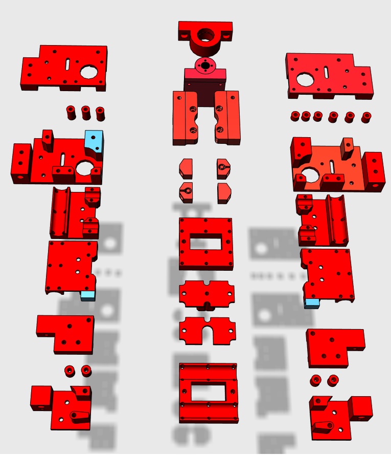
I'm trying to figure out what the minimum printed parts needed is to get this printer going.
I've attached a picture of what I think those parts are. Am I missing something?
Are all the red parts in the 123d cad file = printed parts?
Thanks.
I've attached a picture of what I think those parts are. Am I missing something?
Are all the red parts in the 123d cad file = printed parts?
Thanks.


Sorry, only registered users may post in this forum.