|
Re: looking to build new printer, what sliding mechanisms should i use? September 20, 2015 02:36PM |
Registered: 9 years ago Posts: 34 |
Quote
bradleyk
i did think about using that or a similar design, but thought the ballscrew would give better results.
i might need to have a look at building a test one using that design.
RichRap has done that aswell. but he used a geared stepper. here
Yes, sorry, I forgot to mention that you need a geared stepper (or additional gearing) - I pinched the idea from Sli3DR but I'm using a smaller diameter drum than RichRap to further increase the torque because I've got a quite heavy 200 x 400 mm build plate.
I'm also using adjustable tensioners on the cable (on one of the bed supports) so I can fine adjust the left / right height of the build plate.
The design is quite rigid and I'm pleased with it.
|
Re: looking to build new printer, what sliding mechanisms should i use? September 20, 2015 11:34PM |
Registered: 12 years ago Posts: 30 |
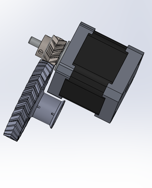
i have been through a few iterations. I don't like the 2:1 pulley system, it looks messy and uses lot's of v bearings. i think this might be the best solution. I would love to use a geared stepper. might look at getting one. but $30 more. I could buy 1kg of abs for that. i will need to design a support housing for it. It has a 4:1 gear ratio.

|
Re: looking to build new printer, what sliding mechanisms should i use? September 21, 2015 07:50AM |
Registered: 9 years ago Posts: 346 |
If you can really run 2A stable on the DRV8255 driver, then that might just be the solution. Twice the stable A4988 current. I sure ordered 5 of them last night to try just that out.
Then you just need one of the bigger Nema 17. Like the 17HS8403 (2.3A).
Downside is that you will not be (easily) able to upgrade to Duet later. But some of the Arduino Due (32 bit) boards with modified Ramps should still work...
I tried the path you are walking down now, with designing my own gear box. I gave it up already in the design phase. I didn't trust that I could get the precision I wanted. Also I don't remember seeing any designs out there using a printed gearbox for the axis movement. Remember that any variations on your printed gear goes directly into your Z axis movement.
|
Re: looking to build new printer, what sliding mechanisms should i use? September 21, 2015 09:33AM |
Registered: 12 years ago Posts: 30 |
|
Re: looking to build new printer, what sliding mechanisms should i use? September 21, 2015 11:49PM |
Registered: 11 years ago Posts: 1,049 |
If the line wraps on itself the shaft radius changes -- changing Z lift per step
Since your talking microns overwrap is a lot?
You need to use a screw or winding mechanism to keep line flat?
I would think string (spectra line) should only be used in Pull-Pull system
A geared stepper motor would help
a stepper motor brake could also be used to keep bed from dropping
To make it more fun
----You could add a linear encoder to measure Z movement and correct for movement
with firmware / software full feedback system --- you could have angstrom resolution?
Quote
cristian
Quote
LarsK
Imagine if you put a stepper on that spectra wire and then you can just remove the ball screw completely. Never tried anything like it but would be really interesting. Ball screws are really what kicks the printer costs up.
I use some cheap spectra line for the Z axis of my smartrap: no wobble, almost zero cost, Z resolution of about 50 microns per full step. That is one problem that I solved completely, among thousands (that will be solved by a new printer).
|
Re: looking to build new printer, what sliding mechanisms should i use? September 22, 2015 11:47AM |
Registered: 9 years ago Posts: 344 |
Quote
cozmicray
If the line wraps on itself the shaft radius changes -- changing Z lift per step
Since your talking microns overwrap is a lot?
You need to use a screw or winding mechanism to keep line flat?
Thanks to a little geometrical trick, it is possible not to use screws or other winding mechanism to avoid line wrapping on itself. You just need a stepper motor spinning a round shaft, and a small horizontal distance between the points where the line is attached. The number of steps per mm must be adjusted accordingly, of couse. Given the small size of my printer, I managed to roll the line directly on the (round) shaft of the motor without need of extending it.

|
Re: looking to build new printer, what sliding mechanisms should i use? September 23, 2015 11:52AM |
Registered: 10 years ago Posts: 553 |
That would cause the z axis to move a different rate as it moves along the axis.
It is the same principle as why you need to make the belts parallel/perpendicular to their respective axis the CoreXY mechanism.
greghoge.com
HUGE 3D PRINTER PARTS SALE!!!
It is the same principle as why you need to make the belts parallel/perpendicular to their respective axis the CoreXY mechanism.
greghoge.com
HUGE 3D PRINTER PARTS SALE!!!
|
Re: looking to build new printer, what sliding mechanisms should i use? September 23, 2015 01:36PM |
Registered: 9 years ago Posts: 344 |
|
Re: looking to build new printer, what sliding mechanisms should i use? September 24, 2015 10:22AM |
Registered: 10 years ago Posts: 553 |
Unless you are using some kind of variable steps/mm value that is dependent on the height of the z carriage, I don't see how it could give you the same linear distance with each turn of the shaft.
Based on the drawing you posted, the carriage would move faster at the bottom of it's movement and slower at the top because the angle that the spectra line makes with vertical does not stay the same.
Granted, if you're printer is small enough and the "horizontal gap" is small enough, then the effect may be negligible, but that does not mean it does not exist.
greghoge.com
HUGE 3D PRINTER PARTS SALE!!!
|
Re: looking to build new printer, what sliding mechanisms should i use? September 24, 2015 02:48PM |
Registered: 9 years ago Posts: 344 |
Quote
gmh39
Based on the drawing you posted, the carriage would move faster at the bottom of it's movement and slower at the top because the angle that the spectra line makes with vertical does not stay the same.
In my experience this is false, unless you break one or more conditions that are somehow implicit in the picture (the wire must not be too thick, it must stay on the same side w.r.t. the vertical shaft, the vertical change of position must be 1:1 w.r.t. to the rotation of the shaft, the wire must first have been rolled bottom-up to get a regular coil, the attachment points must be properly aligned in the 3rd dimension that is flattened in the picture, ...).
As an empirical proof, it should be enough to verify that the distance between two adjacent turns does not change over the whole coil. I tried with a wire about 1 meter long rolled on a 10mm diameter tube, at an angle of about 45°. I did not notice any change. I have never tried to write an analytical proof instead, so let us see if it works also that way.
It should be possible to write the angle as a differential equation. If the vertical change of position of the carriage is Y (Y = 0 --> unrolled wire, carriage at the bottom), H is the height of the (center of the) motor shaft with respect to the carriage at Y = 0, D is the horizontal distance between the point where the wire is fixed on the motor shaft and the center of vertical shaft, X is the horizontal distance between the point of attachment of the wire on the motor shaft and the point where the wire starts rolling up (X = 0 <--> Y = 0), then we can compute (or better, define) the angle as a function of X and Y
angle(X, Y) = arctan((D - X)/(H - Y)) = arctan(f(X, Y))where the angle is the one between the vertical shaft and the line. Consequently, the angle is constant if and only if f(X, Y) = (D - X)/(H - Y) stays constant. So let us see what happens to X and Y. An infinitely small change of X depends linearly on the change of Y and the current angle. If we suppose to work where tan(angle) is invertible, we have
dX = tan(angle(X, Y)) dY = tan(arctan(f(X, Y))) dY = f(X, Y) dYHere we actually see the differential equation (please, guess by yourself the symbol of partial derivatives that I don't know how to write here). For the (total) differential of f(X, Y) we have in general
d f(X, Y) =
                 - dX         / (H - Y) + (D - X) dY / (H - Y)2
               = - f(X, Y) dY / (H - Y) + (D - X) dY / (H - Y)2
               = - f(X, Y) dY / (H - Y) + f(X, Y) dY / (H - Y)
               = 0
If I did not make mistakes, the differential of f (and consequently of the angle) is actually zero everywhere, which means it does not change if you roll the wire. Therefore, if you unroll a wire that was correctly rolled in the first place, the angle should never change.Quote
gmh39
Granted, if you're printer is small enough and the "horizontal gap" is small enough, then the effect may be negligible, but that does not mean it does not exist.
This is indeed the case in my printer where the ratio of motor rotation/vertical shift is 2:1, that is one of the above conditions was not respected. As you observed, the error is not noticeable on the printed pieces since the wire is thin, which makes the "horizontal gap" small.
Edit: I am sorry if I hijacked the thread, it was not my intention.
Edited 1 time(s). Last edit at 09/24/2015 03:48PM by cristian.
|
Re: looking to build new printer, what sliding mechanisms should i use? September 30, 2015 09:14PM |
Registered: 10 years ago Posts: 179 |
You can get the supported linear rods with adjustable bearings. These are presicion rods with an aluminium extrusions attached to them at one third of Hiwin system price. I would use them for Z and Y axis. For X axis I would use something lighter.
Edited 1 time(s). Last edit at 09/30/2015 09:14PM by Edvardas.
Edited 1 time(s). Last edit at 09/30/2015 09:14PM by Edvardas.
|
Re: looking to build new printer, what sliding mechanisms should i use? October 17, 2015 10:19PM |
Registered: 12 years ago Posts: 30 |
i have used the supported rails on my cnc machine, they are nice at 20mm, i haven't liked the play at 8mm. you can get a cheaper version of the hiwin system Here, i don't know how they would preform. would be eaiser to mount. i am currently thinking of a dual x carriage. Tho it would require a total change of design for dual carriages.
|
Re: looking to build new printer, what sliding mechanisms should i use? November 01, 2015 05:36PM |
Registered: 12 years ago Posts: 30 |
I have been through 5 redesigns so far and haven't found one i like. I would like to look at dual carriages. I am going to make one with mdf to see if i can get dual carriages working with core-xy. I am going to follow you advice and go with hiwin, 32bit, and keep my current printer operational. i still want to go with Spectra line. will see how it holds up on the mdf printer.
im not looking for anything faster 100mm/s at this point.
[onedrive.live.com]
i am planing to order 2 mgn9 at 400mm for the y axis and 1 mgn7 for the x
Edited 1 time(s). Last edit at 11/01/2015 05:37PM by bradleyk.
im not looking for anything faster 100mm/s at this point.
[onedrive.live.com]
i am planing to order 2 mgn9 at 400mm for the y axis and 1 mgn7 for the x
Edited 1 time(s). Last edit at 11/01/2015 05:37PM by bradleyk.

Sorry, only registered users may post in this forum.