Building a No Name big printer
Posted by bonmotwang
|
Re: Building a No Name big printer October 15, 2015 07:18PM |
Registered: 8 years ago Posts: 78 |
Quote
patrickrio
I am using 400 step 78 oz inch 1.8 amp nema 17 motors, and I am only using .8 amps at 24v... I am almost certain that these would have enough power for your setup too... especially if you turned them up in amps. Then you can use standard control boards and drivers... I highly recommend the Duet board as it has a wonderful ethernet interface that I operate with my telephone.
I bought them on ebay, this is the description:
Nema17 stepper motor 0.9 deg /48mm/ 78 Oz-in / 1.8A CNC stepper motor
( 151660524251 ) ITEM PRICE: US $13.84 free shipping from China
Thanks again Patrick. Reference design information is priceless. Now I feel better about my design for mounting the motors: very easy to change the motors. :-)
I would agree with you about Nema17 probably is big enough for this machine. The Nema 23 in my drawing is from the desktop CNC machine I made which needs to handle much bigger cutting force.
Printer I bought: 2015 Sunhokey Prusa i3
Printer I am designing: Another big CoreXY machine
|
Re: Building a No Name big printer October 15, 2015 08:34PM |
Registered: 8 years ago Posts: 78 |
Hey Patrick
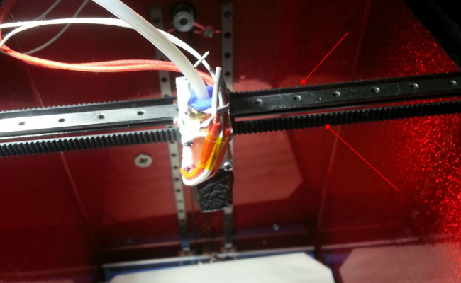
I noticed that your belt facing is not same as mine:
In mine design it is opposite where the arrows are pointing at. I guess you twisted the belt at where they cross?
Thanks
Printer I bought: 2015 Sunhokey Prusa i3
Printer I am designing: Another big CoreXY machine
I noticed that your belt facing is not same as mine:
In mine design it is opposite where the arrows are pointing at. I guess you twisted the belt at where they cross?
Thanks
Printer I bought: 2015 Sunhokey Prusa i3
Printer I am designing: Another big CoreXY machine
|
Re: Building a No Name big printer October 15, 2015 10:49PM |
Registered: 8 years ago Posts: 78 |
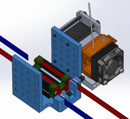
This is my fancy belt holder.
Printer I bought: 2015 Sunhokey Prusa i3
Printer I am designing: Another big CoreXY machine
Printer I bought: 2015 Sunhokey Prusa i3
Printer I am designing: Another big CoreXY machine
|
Re: Building a No Name big printer October 16, 2015 08:30AM |
Registered: 9 years ago Posts: 233 |
sorry, I do not have pictures of how my carriage clamps belts... but I actually used one continuous belt for mine, and just clamped the center of that belt solidly in place at the nozzle to turn it into two belts. On the other side of the nozzle carriage block, the two cut ends of the belts are clamped by circling a 2mm bolt shaft each, interlocking the teeth on the belt and clamping together. My belts BOTH twist once at the back of the machine, and pass each other without rubbing. My belts can thus be on the same level as each other. I have had NO problems with the belt even with this twist. A 6mm belt can be twisted 180 degrees in 25mm distance and still stay within operating specifications. The most difficult part of having a twist is that you need to be able to adjust pulleys on each side of the twist up and down a little bit to allow them to pass, and to make sure your belts don't rub one edge of those pulleys.
Belt facing depends on a combination of if you locate the motors at the front or back, where you locate your belt flip if you have one, and whether you add some extra pulleys that allow you to locate the drive gear/motor assemblies on the other side of the belt. With design changes you can have the belts face any way you want at the carriage.
From your drawing, it becomes clearer that the back of your carriage/extruder mounting u is not structurally necessary and should be removed to reduce weight OR turn the mount into an O to increase structural integrity. I would also flip the belt clamp screws so they can be tightened from the other side, so you can mess with the clamps without removing your extruder.
You should look through your extruder carriage design and reduce the size and number of parts to reduce the carriage weight. The lighter the carriage, the faster you will be able to accelerate it. For example: if you change your carriage mount so it uses the motor holes for mounting instead, you will remove a lot of weight and simplify the design too. you can have the carriage mount plate go between the extruder motor and the extruder hob/lever assembly. Making that work just requires slight lengthening of the 4 motor/extruder mounting bolts and moving the hob down the motor shaft just a bit. Better to use existing mount points and hardware for multiple uses I think.
|
Re: Building a No Name big printer October 16, 2015 09:01AM |
Registered: 9 years ago Posts: 233 |
Here is a picture of the back of my carriage, showing the clamps. You can also see the micro switch used for X limit. My infra red Z probe and bed level tester is not attached, nor are the wires attached to the micro switch at the moment. Screws used are all 2 mm size and you can see a bit of my hand, so you can tell that my carriage assembly is quite small.
Edited 1 time(s). Last edit at 10/16/2015 09:02AM by patrickrio.
Edited 1 time(s). Last edit at 10/16/2015 09:02AM by patrickrio.
|
Re: Building a No Name big printer October 16, 2015 11:04AM |
Registered: 8 years ago Posts: 78 |
Yes, the mounting plate could be changed or removed for a lighter design. And I am planning to do my version of MK8 too. So that the extruder plate could be designed to be bolted onto the mounting block directly without a clamp.
The U shape is designed as a universal mounting plate for now.
At the final stage of the design tweaking, I will review the mass properties and reduce or remove redundant structures. Yes the U is heavy, it is 191 grams asis.
The belt holder screws could be facing either way because the extruder could be mounted on either side of the U. But if I change it to L, then I have to pick which side.
Good pick though!
Edited 1 time(s). Last edit at 10/16/2015 11:06AM by bonmotwang.
Printer I bought: 2015 Sunhokey Prusa i3
Printer I am designing: Another big CoreXY machine
|
Re: Building a No Name big printer October 16, 2015 01:19PM |
Registered: 9 years ago Posts: 233 |
I am also VERY SURE that you will not get the extrusion speed out of that setup that you need for a large printer like yours. The Core XY movement is capable of very fast and accurate extrusion, but you will be limited by that extruder setup.
Edit: I created a new topic asking for help on this issue HERE:
General forum Extruder Question Link
As I said before, I have essentially the same mechanicals as you, but with a short 35cm bowden tube. I get a maximum print speed of about 200mm/sec at 0.4mm nozzle size before it gets difficult to tune my extruder mechanicals. The best I have done is 250mm/sec with extreme tweeking to keep the mechanicals from slipping and chewing up the filament. It gets worse with about 100mm/sec top speed with the 1.2mm nozzle. My build volume is 200x200x260mmm and it just seems really slow when printing big parts even at top speed currently. It can do better without the extruder limitation.
Your design also uses a lower torque 200 step motor, and may not even be able to do the speeds I am getting....I think that the 400 step motors reduce pulse force and thus decrease the likelyhood of chewing the filament and/or missing steps for the same motor torque.
It is too bad, because the coreXY design can do much better speed and just completely outstrips the capability of these direct drive solutions. I am looking into some other designs that provide higher torque via gearing and/or dual sided tooth grip on the filament. I will list them so maybe we can research together:
Flex3Drive flexible shaft system:
[www.youtube.com]
Bondtech Geared Extruder (seems like it may create the highest force, but expensive):
[www.youtube.com]
PrintrBot Gear Head:
[www.youtube.com]
Wade's Reloaded Belted Extruder:
[www.youtube.com]
Modified Wade's Extruder:
[www.youtube.com]
Purchaseable kit Wade's Reloaded
[www.makergeeks.com]
[www.lulzbot.com]
Edited 1 time(s). Last edit at 10/16/2015 02:23PM by patrickrio.
|
Re: Building a No Name big printer October 16, 2015 02:04PM |
Registered: 8 years ago Posts: 78 |
Bowden design takes much less footprint than the direct drive. I want to make sure it has enough room to be able to mount a direct drive in the future.
My plan is to use both. At least I can try both. Because this is my first 3D printer design. It probably will become a test platform for future revisions.
I like Flex3Drive system. It is also in my test list.
Thanks for all the links. Patrick.
Edited 1 time(s). Last edit at 10/16/2015 02:05PM by bonmotwang.
Printer I bought: 2015 Sunhokey Prusa i3
Printer I am designing: Another big CoreXY machine
 Thermal expansion difference between aluminum and steel could be a problem Thermal expansion difference between aluminum and steel could be a problem October 31, 2015 05:42PM |
Registered: 8 years ago Posts: 78 |
This has always been a question mark in my mind.
So I did a calculation. A 500mm aluminum beam changes 0.5mm from 20C to 60C. A 500mm steel beam changes 0.2mm from 20C to 60C.
0.3mm difference is a problem because steel linear guide rail will be mounted on the aluminum extrusion.
It will be a little disappointing if this printer cannot print ABS in a heated enclosure.
Doing more research on the Net right now to see how big of issue this is.
There are several printers here with beams at least 500mm long, has this ever been a problem when the whole thing is heated to around 60C for printing ABS?
Again, I am just do my evaluation purely from "books", I will need some real experience from whole assembly point view from you guys. Thanks.
Printer I bought: 2015 Sunhokey Prusa i3
Printer I am designing: Another big CoreXY machine
|
Re: Building a No Name big printer November 02, 2015 01:32PM |
Registered: 9 years ago Posts: 294 |
I built this one. [www.openbuilds.com]
It was love at first sight, mostly because of the integrated belts and the lack of smooth rods.
I did modify the platform to use 3 screws and 1 stepper instead of the cantilevered design Carl did.
It can be easily scaled to the size u want. Mine is 12"x12"x12" or 305x305x305mm (z ~= 290mm actually)
dual hotends. I modeled it first so I could reduce the width by about 2 inches.
Others have built rather tall versions of this.
So far, I don't think any one has gone over 12x12
U may get some ideas from it.
good luck
|
Re: Building a No Name big printer November 02, 2015 08:31PM |
Registered: 9 years ago Posts: 83 |
If you're going to do a large C-Bot, take a look at the triple C-Bot, which uses 3 lead screws for the Z-axis instead of a cantilever.
openbuilds.org
openbuilds.org
|
Re: Building a No Name big printer November 03, 2015 09:06AM |
Registered: 9 years ago Posts: 294 |
|
Re: Building a No Name big printer November 04, 2015 12:16AM |
Registered: 9 years ago Posts: 31 |
|
Re: Building a No Name big printer November 04, 2015 10:27AM |
Registered: 9 years ago Posts: 294 |
this is my model from Sketchup. Real life looks the same. The adj bar is made from scrap pieces so it doesn't look as pretty as the model.
The pulley wrap is not as much as Adam's design but it works and I have a heavy 5/8" 15x16 MDF build platform. The Z axis also moves a lot faster than the default Marlin settings.
Let me give u a few hints;
Mr Metric is the best place to buy screws if u can make one order (shipping cost). Order extra different sizes than what u calculate. U will probably need them, I did.
These r great steppers cheap. The 6th one is only $4.00 more. (at least it was when I bought them, shipping cost diff.)
[www.automationtechnologiesinc.com]
Openbuild's screws will not work with a brass nut. U must use their Delran nut -- unless u want to file all the buurs out of the entire length of the screw threads, which I did.
Mine is ~2" narrower than Carl's. I didn't like how wide his was, hence, CCBOT = Compact CBOT.
That and the platform change is why I had to model it. For a first time Sketchup user I can't believe it all fit.
The bottom corners are my design - posted on Carl's thread. They r very ridgid once assembled.
The 2 piece screw base is my design. The platform wheel end pieces r also unique but I had to tweak them after printing to make them fit snug.
I haven't tweaked the design yet.
The hardest part of this platform design is getting the screws aligned properly. If they r slightly off the platform WILL bind in the bottom 1/4 - though using Delran nuts might have helped this issue. Also more pulley wrap MIGHT have overcome some of the binding. My bottom screw anchors r adjustable in/out (which is why they r in 2 pieces). If u want to avoid this issue, don't use the bottom 1/4 (or 1/5th) of travel.
Most all the other pieces r Carl's design. ANOTHER SHOUT OUT TO CARL. My endstops and placement r unique. A few extra pieces and some extra holes in Carl's pieces.
One change I made to the carriage piece RE the belt anchors on the hotend side that I think is important: see plate notch
This allows the belt to go under and hook around the plate keeping it in the rail groove and it provides a more secure anchor - using far less clamping force. If u try to clamp these too tight it WILL destroy the plate. The belts on the back are left long to allow easier grabbing when thightning.
NOTE: my front is opposite the motors (motors r on the back) and the hotends r facing the front, so when the belt comes around this the grooves r also on the correct side for the clamp. Otherwise, u will need to turn the belt over.
good luck
|
Re: Building a No Name big printer December 31, 2015 05:07PM |
Registered: 8 years ago Posts: 78 |
|
Re: Building a No Name big printer January 12, 2016 11:24AM |
Registered: 8 years ago Posts: 78 |
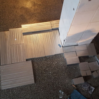
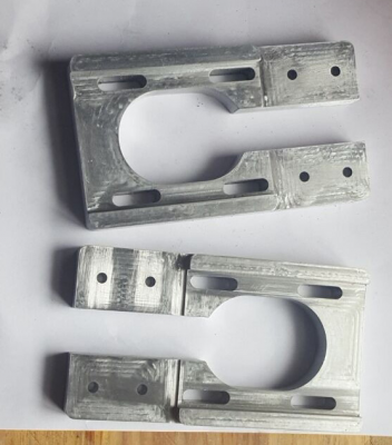
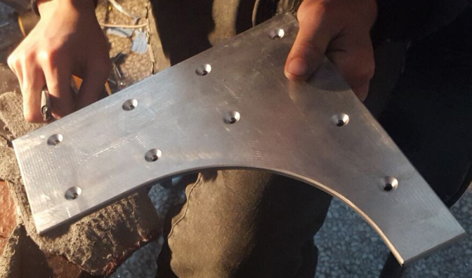
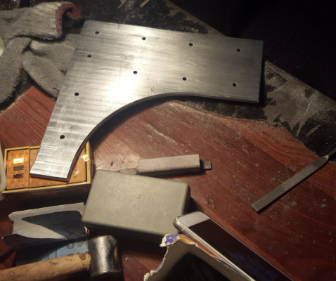
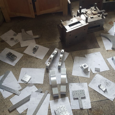
More progress: 90% done with the CNC parts.
Printer I bought: 2015 Sunhokey Prusa i3
Printer I am designing: Another big CoreXY machine
Printer I bought: 2015 Sunhokey Prusa i3
Printer I am designing: Another big CoreXY machine
Sorry, only registered users may post in this forum.
