Best Z-axis configuration?
Posted by Edvardas
|
Re: Best Z-axis configuration? April 25, 2016 08:30PM |
Registered: 8 years ago Posts: 3 |
Quote
robkar
I guess your biggest issue would be that the scissor lifts Z motion doesn't have a linear relationship to the rotation of the motor..
Do you mean in terms of the lead screw (and thus the motor) being oriented off axis relative to the direction of lift, or does the motor rotation to Z travel ratio change as the scissor extends?
*EDIT* NM, it's the latter. Took some creative googling to find. Most of the scissor lift stuff I found had more to do with calculating required force or torque than relative axis travel.
I was kind of hoping it would make for a low cost approach relative to multiple lead screws. Ah well.
Edited 2 time(s). Last edit at 04/25/2016 09:10PM by ThistleDown.
|
Re: Best Z-axis configuration? April 26, 2016 04:10AM |
Registered: 9 years ago Posts: 1,035 |
I am sure I've found more info about this one some time ago (maybe a year or so), but you can have a look at it:
[www.youtube.com]
I agree the most challenging part will be implementing/adding it to Marlin/Repetier/etc ... as far as I know there is no such code implemented.
I would look at scissor lifts that have the scissor mechanism in more than one axis, for added stability and to ensure vertical precision movement:
[www.enkon.pro]
But I don't know how economically feasible would such an endeavor be compared to naked screws. What weight do you want on the bed that a scissor lift is needed?
Regards.
RepRap Lander concept on Concept Forge
RepRap Lander concept on RepRap Forums
My Things, mostly experimental stuff
|
Re: Best Z-axis configuration? April 26, 2016 08:56AM |
Registered: 10 years ago Posts: 14,672 |
Adding motion support to RepRapFirmware for scissor lift would be easy. The more challenging part is calibration. The firmware would need to know the exact geometry of the scissor when the homing switch is triggered, because any error would result in non-linear drive.
Large delta printer [miscsolutions.wordpress.com], E3D tool changer, Robotdigg SCARA printer, Crane Quad and Ormerod
Disclosure: I design Duet electronics and work on RepRapFirmware, [duet3d.com].
Large delta printer [miscsolutions.wordpress.com], E3D tool changer, Robotdigg SCARA printer, Crane Quad and Ormerod
Disclosure: I design Duet electronics and work on RepRapFirmware, [duet3d.com].
|
Re: Best Z-axis configuration? April 26, 2016 09:58AM |
Registered: 8 years ago Posts: 776 |
Quote
realthor
The perfect backlash-free gearbox that I'd try with this material or nylon is a re-design of the harmonic hyperdrive that OskarPuzzle youtube user presented quite recently. Here's an image of the thing:

totally cool - it's actually a belt-drive, where the "belt" (in blue) is also plastic but is thin enough to be flexible. awesome design.
Edited 1 time(s). Last edit at 04/26/2016 10:07AM by lkcl.
|
Re: Best Z-axis configuration? April 26, 2016 09:59AM |
Registered: 8 years ago Posts: 3 |
Quote
realthor
What weight do you want on the bed that a scissor lift is needed?
Wasn't a weight thing. I was just trying to think of a way to use a single screw without cantilevering the platform. I was thinking the platform would be attached to frame mounted guides (linear or rod, ideally 4 rather than 2) like in other designs, the scissor would just be for motivation. The scissor (if workable) would center the lifting force directly under the platform instead of at the edge, eliminating/sidestepping the cantilevering issue.
On top of the software aspect though, the whole idea would hinge on being able to build a scissor lift of suitable precision. This might be possible with off the shelf parts (I'd have to check), but if it added up to more than the cost of a second lead screw the whole thing would be moot.
Though TBH, the more I think about it, the more it seems a purely belt driven pulley system would be the simplest and cheapest solution. The X and Y axis are belt driven with most coreXY designs, so that in itself seems to demonstrate it should be sufficiently stable and precise. And it wouldn't require special modification to the firmware, or special calibration issues.
|
Re: Best Z-axis configuration? April 26, 2016 10:09AM |
Registered: 9 years ago Posts: 1,035 |
Quote
lkcl
Quote
realthor
The perfect backlash-free gearbox that I'd try with this material or nylon is a re-design of the harmonic hyperdrive that OskarPuzzle youtube user presented quite recently. Here's an image of the thing:
totally cool - it's actually a belt-drive, where the "belt" is also plastic but is thin enough to be flexible. awesome design.
I am pretty sure the linked design uses rigid-only parts, not quite like other harmonic drives with flexible barrel that is interposed in the rotation of the exterior gears ... That's why I liked it. It can be totally printed in rigid material should one know how to design/dimension it properly. Ultimately it can be lasercut from some material of sorts and really used as a reduction mechanism.
RepRap Lander concept on Concept Forge
RepRap Lander concept on RepRap Forums
My Things, mostly experimental stuff
|
Re: Best Z-axis configuration? April 26, 2016 11:44AM |
Registered: 8 years ago Posts: 776 |
Quote
Edvardas
So what are your ideas?
my favourite - if i was making a fixed-size printer (i'm not - i'm doing a portable collapsible one) - would be a bar-rod-bar at one end and rod-rod at the other. rods connected by a belt, powered by only the one stepper motor. you could actually have a small gear on the motor and large gears on all three rods, so you could use high-pitch lead screws. you would also need a fairly rigid bed (a frame underneath it), if it was a 200x200 those prusa "alu mk 3 kits" from reprap.me would do the job, as you get a piece of thick acrylic with it that you can attach extrusion to, underneath, and it's pretty solid.
or, instead of bar-rod-bar you would use rail-rod-rail. basically, rods or rails, you'd only need them at one end, because the pair of bars (or rails) prevent rotation about the z-axis and any kind of sideways movement in the x-y plane. thus, you *don't* need bars (or rails) at the other end, because the stiffness of the bed at one end prevents the other from moving. the two rods / lead-screws at the other end would keep the bed level, and prevent see-sawing. the three rods / lead-screws act as a three-point levelling system.
you could actually have the pair of bars (or linear rails) in the middle edge of the bed, so it would be:
- rod / lead-screw in middle at back
- bars with linear bearings / linear rails left and right half-way along
- dual rod / lead-screw in middle at *front*, one left, one right
only one bar is not sufficient, as it would allow rotation. also what would not be sufficient would be those linear rails that have enough flex in them to bend in one direction. you definitely need linear rails that are strong enough to not have any flex in any direction. extrusion with delrin rollers would be perfect.
so yeah, that's what i would be doing... if i was making a fixed-frame 3d printer, as i particularly like the belt-drive gearing you could get out of it (with no backlash, because it's belt-drive) and that you could use lead screws as a result and still have good z-resolution. actually really good z-resolution, depending on how big you make the gears on the lead screws.
-- sandwich200: compact portable folding corexy printer [reprap.org]
|
Re: Best Z-axis configuration? April 26, 2016 12:45PM |
Registered: 11 years ago Posts: 5,780 |
This sort of stuff is interesting, but realistically it isn't going to do the job. The Z axis, like the others, has to move very precisely- errors of a few microns from one layer to the next produce visible artifacts in the prints. If your goal is to makes something that's printable and sort-of works, this will be OK, but the topic of this thread is the "best Z-axis configuration". "Best" won't include printed parts.
Ultra MegaMax Dominator 3D printer: [drmrehorst.blogspot.com]
Quote
realthor
The perfect backlash-free gearbox that I'd try with this material or nylon is a re-design of the harmonic hyperdrive that OskarPuzzle youtube user presented quite recently. Here's an image of the thing:
Ultra MegaMax Dominator 3D printer: [drmrehorst.blogspot.com]
|
Re: Best Z-axis configuration? April 26, 2016 02:47PM |
Registered: 9 years ago Posts: 1,035 |
If this was machined or laser-cut why would it underperform compared to normal geared steppers? Is it plastic parts that you are talking against or 3d printed parts specifically? If the same materials are considered I see this outperform normal gears.
RepRap Lander concept on Concept Forge
RepRap Lander concept on RepRap Forums
My Things, mostly experimental stuff
RepRap Lander concept on Concept Forge
RepRap Lander concept on RepRap Forums
My Things, mostly experimental stuff
|
Re: Best Z-axis configuration? April 27, 2016 01:26AM |
Registered: 8 years ago Posts: 776 |
Quote
realthor
If this was machined or laser-cut why would it underperform compared to normal geared steppers? Is it plastic parts that you are talking against or 3d printed parts specifically? If the same materials are considered I see this outperform normal gears.
yeah i have to agree here: this is an incredibly precise design, with zero backlash. even in 3d-printed parts i'd see this being really still very good. the only down-side is that it's like a planetary gear (outside ring design), so getting the drive off of it would be... interesting. if however you put a belt (and teeth) round the outside ring, that would do the trick: you'd be able to wrap a belt round it. the only thing is: 300+ to 1 gear ratio, wow! even with no microstepping the z-axis motor would be going mental!

|
Re: Best Z-axis configuration? April 27, 2016 01:52AM |
Registered: 8 years ago Posts: 776 |
Quote
robkar
I guess your biggest issue would be that the scissor lifts Z motion doesn't have a linear relationship to the rotation of the motor..
more than that, you have at one point an "overgearing" situation, followed by (at 45 degrees) a 1:1 gearing ratio, followed immediately by *under*gearing. worst-case: if you let the scissors drop to zero degrees, you have an impossible situation: infinite-to-zero gearing.
thinking about predictability, reliability and possible (useful) range, i considered the scissor-lift (for a portable 3d printer) and completely ruled it out due to the extreme range of gearing, which would translate directly into an extreme range of high torque at one end of travel and high RPM at the other. both extremes are almost certainly out of the practical range of what is needed for 3d printing, taking into account what equipment we have available today.
then, also, there are two other issues: the joints (swivel-points) and the accuracy required on machining the bars in the scissor-lift. i did once consider a Sarrus Linkage for a bed lift arrangement: it has in fact been used. however the machining tolerances required on all the bars and joints in scissor-lift and sarrus linkages are even *more* extreme than those required for delta printers. the reason is that you end up with tiny differences being multiplied by 1/cos(angle), where when angle is small, the multiplier becomes huge. machining tolerances of 1/10th *OR LESS* than the accuracy required would not be unreasonable because of that inverse-multiplier.
in short: scissor lifts as a precision linear mechanism are way outside of the reprap 3d printing remit and are completely impractical with the kinds of materials and build considerations we're currently working with in this decade.
Edited 3 time(s). Last edit at 04/27/2016 07:33AM by lkcl.
-- sandwich200: compact portable folding corexy printer [reprap.org]
|
Re: Best Z-axis configuration? November 13, 2016 12:36AM |
Registered: 9 years ago Posts: 53 |
Quote
dc42
Adding motion support to RepRapFirmware for scissor lift would be easy. The more challenging part is calibration. The firmware would need to know the exact geometry of the scissor when the homing switch is triggered, because any error would result in non-linear drive.
I'm missing something.....in the video, the scissor is driven by a pair of vertical Z screws which exactly determine the Z height; linear... The only role the geometry plays is to keep the bed level...no? Tolerances and joint rigidity might be a different issue.
Quote
Edvardas
AllrightSo I am actually getting better at taking pictures of these small layers. Here is a comparison against aluminium framed prusa i3 print at the same 0.4mm layer height. As you can see belt z-axis print on the left is way more even. And my prusa actually makes nice prints at 0.2mm layer height.

I am really really impressed by the Z quality of the Z-belt drive. Thanks for posting the pics. The Z artifact issues caused by cheap Z lead screw wobble evaporate.
The top belt return does a U turn with belt teeth inwards. Did you use a smooth bearing or toothed idler?
What are your thoughts about going to a 16T drive pulley instead of 20T, still keep the 20T:40T, 0.9 deg stepper, and adding a second belt return for 4:1 instead of 2:1....this should get to 0.01mm step resolution? (this was the diagram I had scribbled down before I found this thread)
I'm not a fan of double Z screw machines machines like d-Bot, because they still rely on wheels/linear bearings to keep the bed from tipping. Vulcanus has some long Z rail bearings which helps, but adds cost and can cut down on Z travel. I kind of like the Triple-C-bot concept. What might be interesting is two smooth Z rails, and three Z-belts. Should easy enough to extend the drive scheme to a second 40T pulley.
Side note. I had been concerned about supporting Z screws from the bottom of the frame. The bed Z height is the difference between the aluminum frame height and the Z screw height. When running in a heated enclosure, the aluminum will expand more than the stainless screw. With 50C temp rise, this can result in the bed dropping by about 0.084mm assuming about 400mm lead screws. Take away is you might have to wait for the frame to cool down before running the next print to get a good first layer. In reality, the external frame will probably be cooler than the lead screw so it might be closer to a wash. But with a belt drive, it should be first order ratio-metic; the belt tension will change, but the position shouldn't? plus glass core belt should have a pretty low Tcoef.
|
Re: Best Z-axis configuration? November 13, 2016 02:46AM |
Registered: 10 years ago Posts: 14,672 |
You are right, in the video the scissor lift is driven by a vertical leadscrew, so it is linear.
Large delta printer [miscsolutions.wordpress.com], E3D tool changer, Robotdigg SCARA printer, Crane Quad and Ormerod
Disclosure: I design Duet electronics and work on RepRapFirmware, [duet3d.com].
Large delta printer [miscsolutions.wordpress.com], E3D tool changer, Robotdigg SCARA printer, Crane Quad and Ormerod
Disclosure: I design Duet electronics and work on RepRapFirmware, [duet3d.com].
|
Re: Best Z-axis configuration? December 08, 2016 05:10AM |
Registered: 10 years ago Posts: 339 |
|
Re: Best Z-axis configuration? December 08, 2016 07:47AM |
Registered: 11 years ago Posts: 5,780 |
edvarda's belt driven Z axis result looks very good, the most like the results I get from my printer's belt driven Z axis screws,
which convinces me that it's worth trying a belt driven Z axis in the coreXY machine I am building. Construction is both easier and lower cost than the alternative I was planning- three screws driven by a single motor. The hardware I ordered is starting to trickle in and I'll be building in a week or so.
In the design I am planning, the bed support will be lifted on two linear guides positioned at the center of opposite sides of the bed. The guides will be mounted directly on two 40x40 mm T-slot beams (not sure how well that's going to work) using t-nuts. If the guides have any play the bed may tilt side to side. I have a plan to test that- I'll mount a laser on the bed plate and project the beam on a distant wall while I move the bed up and down. If there's no play, the laser should move up or down by the exact amount I have moved the motor. Any tilting will cause the laser to deflect more or less than the amount that I commanded the motor to move, and will be exaggerated by the distance from the mechanism to the wall, making it easy to back calculate the error at the bed itself.
Ultra MegaMax Dominator 3D printer: [drmrehorst.blogspot.com]
|
Re: Best Z-axis configuration? December 08, 2016 01:07PM |
Registered: 10 years ago Posts: 339 |
Results are awesome...
But I can't find a picture of edvarda's Z-Belt-System.
I'm wan't to realize a 300x300 print bed and looked für a decent cantilevered design with a trapezoidal thread spindle but I don't know. Maybe I should try a Z-Belt System. But I don't know how to arrange the rods? Maybe left and right centered one rod and at the back centered the Z-Belt?
|
Re: Best Z-axis configuration? December 19, 2016 07:53AM |
Registered: 11 years ago Posts: 5,780 |
Most of the belt driven Z axis construction for my coreXY printer is done - you can see what it looks like here:
[vimeo.com]
and operating under control of the smoothieboard here:
[vimeo.com]
In the last couple days I have designed and fabricated the Z=0 switch. Now I am thinking about how to deal with the rapid drop of the bed when power goes off, when the controller is reset, or when motors are disabled. The one thing that all three have in common is the motor enable lines change state. I'm thinking of picking off the Z motor enable line (or maybe the unused second extruder enable line) and using it to operate a relay. The relay will short the coils of either the Z axis motor or a second motor added to the Z axis that acts only as a brake. Not sure how well that would slow the descent- I'll have to run a test.
Ultra MegaMax Dominator 3D printer: [drmrehorst.blogspot.com]
[vimeo.com]
and operating under control of the smoothieboard here:
[vimeo.com]
In the last couple days I have designed and fabricated the Z=0 switch. Now I am thinking about how to deal with the rapid drop of the bed when power goes off, when the controller is reset, or when motors are disabled. The one thing that all three have in common is the motor enable lines change state. I'm thinking of picking off the Z motor enable line (or maybe the unused second extruder enable line) and using it to operate a relay. The relay will short the coils of either the Z axis motor or a second motor added to the Z axis that acts only as a brake. Not sure how well that would slow the descent- I'll have to run a test.
Ultra MegaMax Dominator 3D printer: [drmrehorst.blogspot.com]
|
Re: Best Z-axis configuration? December 19, 2016 12:44PM |
Registered: 12 years ago Posts: 548 |
|
Re: Best Z-axis configuration? December 19, 2016 12:59PM |
Registered: 10 years ago Posts: 339 |
Looking good! Now place a dial indicator on the frame and measure the repeatability when doing short (and fast) Z-Axis movements. Make sure to do longer movements also to catch more then a fraction of a pulley rotation and do all of this measurements at different Z-heights. I'm looking forward to the results.

Edited 1 time(s). Last edit at 12/19/2016 01:00PM by SturmGhost.
|
Re: Best Z-axis configuration? June 19, 2018 07:08AM |
Registered: 5 years ago Posts: 3 |
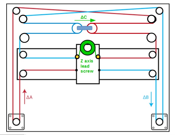
It is possible to add an additional axis ( Z or A) to coreXY by changing the belt lengths. That way all three drive motors remain stationary. Additionally, in my opinion, no change in firmware for XY axis drives in required as is the case for other implemetations of planar belt driven stationary Z axis ( or Extruder ) motor
|
Re: Best Z-axis configuration? June 19, 2018 07:19AM |
Registered: 5 years ago Posts: 3 |
(reposted here) In CoreXY implimentations where the Extruder would move along the Z axis as opposed to moving bed, Its possible to add an additional axis ( Z or A) to coreXY by changing the belt lengths. That way all three drive motors remain stationary. Additionally, in my opinion, no change in firmware for XY axis drives in required as is the case for other implemetations of planar belt driven stationary Z axis ( or Extruder ) motors
|
Re: Best Z-axis configuration? June 19, 2018 07:35AM |
Registered: 9 years ago Posts: 1,035 |
I contemplated the same idea to have a stationary extruder motor by using a belt that would turn the extruder gear but never got time or enough will to try it. I don't really get it in your sketch how the motor will -at the same time- move the selected axis with the speed/accelleration/jerk/etc and push/pull filament through the extruder. I believe that can't be done with only one stepper. But with a stationary extruder motor and a separate belt that could be done... but quite a mess of belts there...
RepRap Lander concept on Concept Forge
RepRap Lander concept on RepRap Forums
My Things, mostly experimental stuff
RepRap Lander concept on Concept Forge
RepRap Lander concept on RepRap Forums
My Things, mostly experimental stuff
|
Re: Best Z-axis configuration? June 19, 2018 02:03PM |
Registered: 5 years ago Posts: 3 |

Sorry, only registered users may post in this forum.