Coffeetable CoreXY:: new build :: small apartment rep-strap solutions
Posted by realthor
|
Re: Coffeetable CoreXY:: new build :: small apartment rep-strap solutions February 26, 2016 06:37AM |
Registered: 9 years ago Posts: 1,035 |
Well time has come to re-consider this build. Although I was only working here and there on the design, there are too many printed parts for such a uncommon/unconventional situation and it frankly isn't worth it for what you get at the end in terms of performance/rigidity. and this would not be compatible down the road would I decide to switch to square tubing or T/V-slot profiles.
I am still thinking of a way to keep the Z stepper motor in one corner but I think I'll just build the XY stage from additional tubing instead of reversing the table's legs-frame and using it alone. So I'd just turn the coffee-table around, insert the whole corexy stage in the existing leg tubes, clamp/fix Z and that's it. More vitamins which I don't like but the design should be upgradable to either full-tubing or T-slot/-V-slot down the road.
In the meanwhile I have released on thingiverse some of the XY stuff like the X Carriage, Y Carriage, the Direct-Contact Z Probe I was working on a separate thread here on reprap forums and an extruder I call Hunchback Extruder.
This is just another update, let me know your thoughts. Thanks.
RepRap Lander concept on Concept Forge
RepRap Lander concept on RepRap Forums
My Things, mostly experimental stuff
|
Re: Coffeetable CoreXY:: new build :: small apartment rep-strap solutions February 26, 2016 09:55PM |
Registered: 9 years ago Posts: 346 |
Having to start partly or completely over on a design happens to everybody. I still have my multicolor hotend sitting on a shelf staring at me ( [forums.reprap.org] ).
Good luck with the new design. I don't know where you are with your Delta, but if it can print then try to print the parts you already designed even if you don't intend to use them. It is a great experience to see your parts alive and get a feel for if what you were thinking of would have worked or how you were off. Plastic is so cheap so if you have the opportunity it is a shame not to grab it.
For example, I am curious if your hotend design would work with all those parts that have to come together. If I am right, and you can't get a tight strong fit with that many parts, then it is something worth carrying over for your next design. And if it works then you know you can make it even more complicated next time.
Edited 1 time(s). Last edit at 02/26/2016 09:56PM by LarsK.
|
Re: Coffeetable CoreXY:: new build :: small apartment rep-strap solutions February 26, 2016 10:28PM |
Registered: 9 years ago Posts: 1,035 |
I printed most of the parts that I have designed and really tried to put everything together but I had at first errors in the way I designed the parts, then I re-did them and noticed errors in me measuring the damn thing  , then the way I reversed the metal frame and bolted it back to the board wasn't very exact so that some of my measurements got off and now my linear rods for Z aren't perfectly vertical...etc
My lesson learned is that if you can't very accurately measure an existing frame and don't have a decent and well calibrated printer to print those parts, it only gives frustration.
So, like they say in finance, I activated my stop loss threshold and learned the lesson to be learned.
I wish everything turned right though, I liked the design so much. BUT, as I've said, at this point it makes no sense.
Now I will try to use more off-the-shelf parts (more tubes, brackets), just to make a decent rep-strap, then go from there. I don't exactly need a 3D printer per se so I'm not in a hurry to get it done. I enjoy the designing and learning process more I guess. But it always boils down to getting things simpler, simplest if possible.
Let me see if I can try to come up with some of the lessons:
- Don't use stuff that you can't measure very precisely to replicate in a CAD form;
- Don't design parts that do multiple functions because if something breaks you'll have to re-print the whole part;
- Try to design for errors (this is difficult to master)
- Until 3D printing will be more exact or easier to order parts (3DHubs/etc), use the rep-strap philosophy as much as possible (off-the-shelf parts)
- You should definitely build a vertical drill stand before any other precision machinery; and have a dremel and a vise. No, really!.
There might be more, but it's 5:24am here and I am doing a remote intervention for my job so I can't focus too well.
PS: my delta is getting dust, I am waiting for Dreammaker to send me another board and motors, the one I have was one of the first batch i guess and it was a mess ... and I didn't enjoyed it so much as I anjoy building from scratch.
RepRap Lander concept on Concept Forge
RepRap Lander concept on RepRap Forums
My Things, mostly experimental stuff
 , then the way I reversed the metal frame and bolted it back to the board wasn't very exact so that some of my measurements got off and now my linear rods for Z aren't perfectly vertical...etc
My lesson learned is that if you can't very accurately measure an existing frame and don't have a decent and well calibrated printer to print those parts, it only gives frustration.
So, like they say in finance, I activated my stop loss threshold and learned the lesson to be learned.
I wish everything turned right though, I liked the design so much. BUT, as I've said, at this point it makes no sense.
Now I will try to use more off-the-shelf parts (more tubes, brackets), just to make a decent rep-strap, then go from there. I don't exactly need a 3D printer per se so I'm not in a hurry to get it done. I enjoy the designing and learning process more I guess. But it always boils down to getting things simpler, simplest if possible.
Let me see if I can try to come up with some of the lessons:
- Don't use stuff that you can't measure very precisely to replicate in a CAD form;
- Don't design parts that do multiple functions because if something breaks you'll have to re-print the whole part;
- Try to design for errors (this is difficult to master)
- Until 3D printing will be more exact or easier to order parts (3DHubs/etc), use the rep-strap philosophy as much as possible (off-the-shelf parts)
- You should definitely build a vertical drill stand before any other precision machinery; and have a dremel and a vise. No, really!.
There might be more, but it's 5:24am here and I am doing a remote intervention for my job so I can't focus too well.
PS: my delta is getting dust, I am waiting for Dreammaker to send me another board and motors, the one I have was one of the first batch i guess and it was a mess
 ... and I didn't enjoyed it so much as I anjoy building from scratch.
RepRap Lander concept on Concept Forge
RepRap Lander concept on RepRap Forums
My Things, mostly experimental stuff
|
Re: Coffeetable CoreXY:: new build :: small apartment rep-strap solutions February 27, 2016 08:24AM |
Registered: 9 years ago Posts: 346 |
Quote
Don't design parts that do multiple functions because if something breaks you'll have to re-print the whole part;
I will say my experience is the opposite, I try to design as complex pieces as possible because every time you have an interface you have an imperfect surface meeting another imperfect and bolts that applies localised stress and variations in the print dimensions.
That was my concern for your hotend and why I would love to see a photo of the printed part if you did it.
|
Re: Coffeetable CoreXY:: new build :: small apartment rep-strap solutions February 27, 2016 10:57AM |
Registered: 11 years ago Posts: 5,780 |
Quote
realthor
I printed most of the parts that I have designed and really tried to put everything together but I had at first errors in the way I designed the parts, then I re-did them and noticed errors in me measuring the damn thing, then the way I reversed the metal frame and bolted it back to the board wasn't very exact so that some of my measurements got off and now my linear rods for Z aren't perfectly vertical...etc
Interesting logic- it didn't work, so you thought it would be a good idea to upload the designs to Thingiverse?
Quote
realthor
- Until 3D printing will be more exact or easier to order parts (3DHubs/etc), use the rep-strap philosophy as much as possible (off-the-shelf parts)
How will 3D printing become more exact if you post designs for printed parts that don't work?
This sort of thing is why I ignore designs on Thingiverse that are unaccompanied by photos of the parts. If there's a photo, at the very least you know the part is printable (many obviously are not), and sometimes the photos show the object in operation so you know it is workable. How many noobs waste time and materials attempting to print/printing designs that can't/don't work?
I know your intentions are good, sharing your designs, but I think it would be better to only share the stuff that works on Thingiverse. You can post everything here, working and not working - this is a good place to show off stuff that doesn't work because you can post a lot of pictures and explain what went wrong. I think that Thingiverse is more of a final repository for designs that work because the audience includes many more inexperienced builders/printers.
Ultra MegaMax Dominator 3D printer: [drmrehorst.blogspot.com]
|
Re: Coffeetable CoreXY:: new build :: small apartment rep-strap solutions February 27, 2016 11:47AM |
Registered: 9 years ago Posts: 1,035 |
I know that complexity is free with 3D printing and there are books around it on the internet but my experience is not as fluid as they would like you to think it is. For example I've come lately to appreciate smarfriendz's Y carriage design that has separate pieces for the smooth rods' clamps... if those break just replace them. Something I laughed at at first. Last week one of my Y carriages broke and I had to redesign, but I don't have a 3D printer easily available, one of my friends that used to help has a busier life and can't at the moment and the hackerspace I used to go to is too far away and the Ultimakers there are completely uncalibrated and nobody knows really how to take care of them.
So, i am falling back to the simplicity mantra, like Antoine de Saint Exupéry said "It seems that perfection is attained, not when there is nothing more to add, but when there is nothing more to take away." Anyway that is more something that designers and architects think about, which is another hobby o mine.
Anyway, the hotends mount and X carriage you were asking about were a bit off, because I have print them on the Ultimakers at the Hackerspace and the circles are not quite round and maybe there are other issues too, so I can't really trust the parts I get out of those. Here are some pics: https://www.dropbox.com/sh/5bfczwfl2veyqkz/AAAGOl5jZqURq2MqBCiDrLL5a?dl=0
Notes: the printhead parts were made at fast speeds and coarse detail settings, just to see how they feel in hand, while the board footings were done at ok quality. But because I couldn't get them to be bolted to the particleboard at very high precision positions, the squareness of the frame is questionable and that was one of the reasons I kind of gave up the ambitious design: I couldn't get it square enough from the base up. I might revise it at some point but for now that was the think that made me move on.
Edited 1 time(s). Last edit at 02/27/2016 11:53AM by realthor.
RepRap Lander concept on Concept Forge
RepRap Lander concept on RepRap Forums
My Things, mostly experimental stuff
|
Re: Coffeetable CoreXY:: new build :: small apartment rep-strap solutions February 27, 2016 09:09PM |
Registered: 9 years ago Posts: 346 |
Modular versus uni-body. Easy configurable and up-gradable versus tailored for the exact purpose.
It is an interesting balance. I went heavy towards modular and upgradable on my first self-designed printer. Lots of parts, many "off the shelf" metal components. The printed parts were small and simple. Prior experience with my delta what I have had to take my effector apart so many times made me want something easy with lots of easy accessible screws.. The result was that it was not rigid enough. Too many small printed parts printed from my poor Delta so they did not fit perfect together.
Still it worked and has worked for a very long time. These days it is down because I am changing from the Chinese ball linear bearings to the Graphite inlaid bronze bushings and that gave some unforeseen problems.
That is the wonder of 3d printers really. You can make the most ridiculous printer print nice things.
It is a shame that your Delta is down. If I was you, I would really invest heavily on getting it back up with a RAMPS board (even if DC will make fun of you for that). Just forget about the bed level sensor and even if you can't get the tower endstops working you can mount some others with plastic strips. That said, looking at the photos of the parts printed at your makerspace; Just by looking at it, it dosen't look bad at all. Looks a lot like any other average printer. You can try to print one of the calibration pieces next time you go and see.
I would recommend you have it print this one:
[forums.reprap.org]
That is a fast one and you have a couple of people who have posted their results, so that should give you a reference for what to expect.
|
Re: Coffeetable CoreXY:: new build :: small apartment rep-strap solutions February 27, 2016 09:21PM |
Registered: 9 years ago Posts: 346 |
|
Re: Coffeetable CoreXY:: new build :: small apartment rep-strap solutions March 01, 2016 12:36PM |
Registered: 9 years ago Posts: 1,035 |
Quote
the_digital_dentist
Quote
realthor
I printed most of the parts that I have designed and really tried to put everything together but I had at first errors in the way I designed the parts, then I re-did them and noticed errors in me measuring the damn thing, then the way I reversed the metal frame and bolted it back to the board wasn't very exact so that some of my measurements got off and now my linear rods for Z aren't perfectly vertical...etc
Interesting logic- it didn't work, so you thought it would be a good idea to upload the designs to Thingiverse?
Quote
realthor
- Until 3D printing will be more exact or easier to order parts (3DHubs/etc), use the rep-strap philosophy as much as possible (off-the-shelf parts)
How will 3D printing become more exact if you post designs for printed parts that don't work?
This sort of thing is why I ignore designs on Thingiverse that are unaccompanied by photos of the parts. If there's a photo, at the very least you know the part is printable (many obviously are not), and sometimes the photos show the object in operation so you know it is workable. How many noobs waste time and materials attempting to print/printing designs that can't/don't work?
I know your intentions are good, sharing your designs, but I think it would be better to only share the stuff that works on Thingiverse. You can post everything here, working and not working - this is a good place to show off stuff that doesn't work because you can post a lot of pictures and explain what went wrong. I think that Thingiverse is more of a final repository for designs that work because the audience includes many more inexperienced builders/printers.
I wish you would look better next time before hammering somebody for something they didn't do
 .
.The designs I have posted on thingiverse are all WIP (if you care to check), meaning they are under active development, and they aren't anything as specific as the parts I tried to design so I can use the steel tubing that was already there in the coffee table design. I wouldn't even post something like that, who would do that? Who else would have such a table around and who from those would want to use it for a 3D printer. C'mon, give people some credit. People aren't that stupid, I wonder what you must think of everybody around here in the forums...
The designs you must be referring to are specific to the CoreXY design, which I have printed and which work, I have them next to me, they are assembled and needed a bit of post processing due to the specifics of the printer I printed them with. And I have those also as WIP if you care to check. I have already updated them several times because I noticed flaws or I broke them when I subjected them to much greater than operation forces but wanted to stay on the safe side.
I agree that only working stuff should go on thingiverse but I also see they have implemented a WIP status that should serve people with a design they can take and tweak or simply for inspiration. I can post there the STL as well as the CAD file, which I can't do here.
But I also agree that people should pay way more attention before jumping to conclusions. Or avoid to take a battle they strongly feel about in relation to thingiverse in general with anybody they stumble upon. At least be right when you do that

Edit: I bet you haven't even looked as far as to notice that many of the components in the images are not present in STL format because they are there in the images just to prove a point and to show the big picture.
Edited 5 time(s). Last edit at 03/01/2016 12:55PM by realthor.
RepRap Lander concept on Concept Forge
RepRap Lander concept on RepRap Forums
My Things, mostly experimental stuff
|
Re: Coffeetable CoreXY:: new build :: small apartment rep-strap solutions March 05, 2016 02:00PM |
Registered: 9 years ago Posts: 1,035 |
Ok, my coffeetable reprap is slowly transforming into a coffeetable-sized frame design  . I'll not call it defeat but evolution
I am on my way to get some alu extrusion for a proper frame but for the purpose of this thread I will continue to explore design iterations and I will eventually build this.
This post is about extrusions, square tubes, round tubes, etc. When you buy ALU extrusion you will most likely get it cut to length by the online shop you buy it from. But I am unable to get T-slot in my area so I am thinking at alu square tube or even steel square tube that is easily found in hardware stores. But these are sold by either 1m or 2m so for a decent size printer one would need at least 12x segments so one will most likely buy a combination of these lengths. And will have to cut them to size either using the store's available saws (we get those here when one exits the store) or use some home equipment to cut them to size.
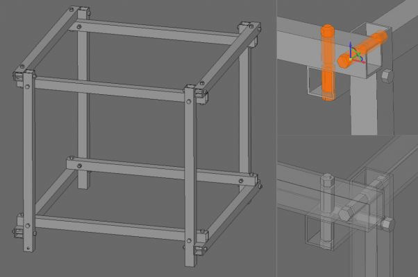
This means that the ends of the segments will not likely be square enough for a perfect end-to-end square connection, like in T-slot's case. I started thinking of ways to build a frame when you can't trust the squareness of the ends (and I don't want to use plastic connectors). Which brings me to this post's subject.
I am sure I've seen this arrangement before, not sure that it was on a 3D printer but on a frame of sorts. It should be nothing new in fact is quite common sense but it only uses the already provided (assumingly) straight faces of the tubes. My question is: is this kind of frame flawed in a terrible way or is there a better way of doing the cross-connection of the tubes, like maybe more smaller bolts instead of 3 larger ones that I have sketched in the below "node"?
With this frame one only needs a good saw and a drill to make it work. I am sure almost anybody has at least these two items in one's toolbox.
RepRap Lander concept on Concept Forge
RepRap Lander concept on RepRap Forums
My Things, mostly experimental stuff
 . I'll not call it defeat but evolution
I am on my way to get some alu extrusion for a proper frame but for the purpose of this thread I will continue to explore design iterations and I will eventually build this.
This post is about extrusions, square tubes, round tubes, etc. When you buy ALU extrusion you will most likely get it cut to length by the online shop you buy it from. But I am unable to get T-slot in my area so I am thinking at alu square tube or even steel square tube that is easily found in hardware stores. But these are sold by either 1m or 2m so for a decent size printer one would need at least 12x segments so one will most likely buy a combination of these lengths. And will have to cut them to size either using the store's available saws (we get those here when one exits the store) or use some home equipment to cut them to size.
This means that the ends of the segments will not likely be square enough for a perfect end-to-end square connection, like in T-slot's case. I started thinking of ways to build a frame when you can't trust the squareness of the ends (and I don't want to use plastic connectors). Which brings me to this post's subject.
I am sure I've seen this arrangement before, not sure that it was on a 3D printer but on a frame of sorts. It should be nothing new in fact is quite common sense but it only uses the already provided (assumingly) straight faces of the tubes. My question is: is this kind of frame flawed in a terrible way or is there a better way of doing the cross-connection of the tubes, like maybe more smaller bolts instead of 3 larger ones that I have sketched in the below "node"?
With this frame one only needs a good saw and a drill to make it work. I am sure almost anybody has at least these two items in one's toolbox.
RepRap Lander concept on Concept Forge
RepRap Lander concept on RepRap Forums
My Things, mostly experimental stuff
|
Re: Coffeetable CoreXY:: new build :: small apartment rep-strap solutions March 08, 2016 03:39PM |
Registered: 9 years ago Posts: 1,035 |
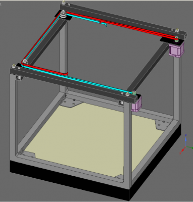
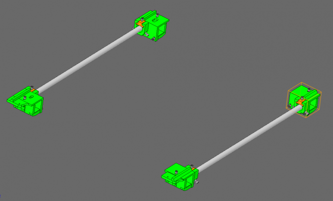
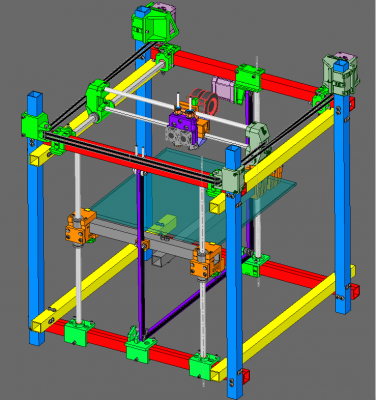
Update: Having conceptualized the previous square tube frame system, I am back to using my existing tubing from the coffee table (20x20 steel tubes) and I am designing some more vitamins in the form of extraneous tubes to complete a parallelogram frame. I have to adapt to the existing structure so I will not be able to replicate exactly the above arrangement but for what it is I will be pretty close. The CoreXY X and Y carriages will remain the same; the new designs are in the frame and in Z system.
The new frame looks like this:
Due to the arrangement of the new tubes, I will not be able to fasten together each with each, like in the previous post's sketch and I fear a bit of loosing sturdiness but that's why I post it here, for your expert eye scrutiny.
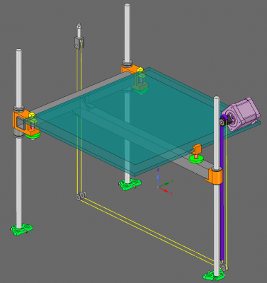
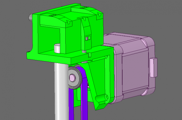
About Z, I have to confess I was never satisfied with the diagonal Z I have proposed in the previous iteration. I wanted by all means to keep a clean look with the motors in the corners and away from the base platform and some of that I continued to do in this new design. The Z is far from being finished, more likely it's an "alpha" release maybe I can squeeze some more useful insight from the people still browsing this thread. Here it is:
I am using a 3 Rods system with belt transmission (or belt-spectra but in this design it really doesn't matter or doesn't make sense to use the spectra part).
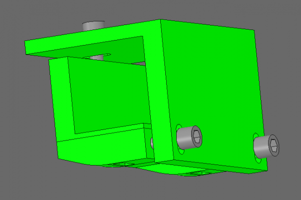
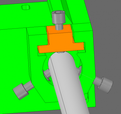
For the Rods I am using a "Centering Collar" type footing to adjust vertical position with the help of 3 screws and insert nuts (barely seen in the picture but you can imagine I am sure). The upper end will be either fixed in a 10mm hole in the upper tube or a larger hole and a similar system. After the first rod is vertical and all lines up perfectly, the next ones will be able to be aligned using the bed, which has to slide up and down effortlessly. The screws' threads will be added a bit of thread locker which will set and freeze the position. Additional epoxy can be added to the larger hole the end of the Rod finds itself into.
The bed supporting frame is a T-shaped 2-plane lightweight aluminum frame (not sure how I will fasten together the two tubes). I am considering brazing them together or using some angles or even screw them together at the intersecting section. Anyway there shouldn't be any sideways movement in the joint.
I didn't find a cheap solution for the bearings to be somehow embedded in the metal design so I will use 3D printed parts. The two rods on one side will have the bed leveling mechanism built-in the clamps while the single rod at the motor side will be decoupled from the bed level adjusting screw. I will talk a bit more in detail about this clamp/adjusting-screw combo in another post.
If you have suggestions, questions, etc, as always, I can't wait to hear them.
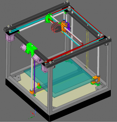
At the end, an overall pic of the new design:
RepRap Lander concept on Concept Forge
RepRap Lander concept on RepRap Forums
My Things, mostly experimental stuff
|
Re: Coffeetable CoreXY:: new build :: small apartment rep-strap solutions March 10, 2016 04:44PM |
Registered: 9 years ago Posts: 1,035 |
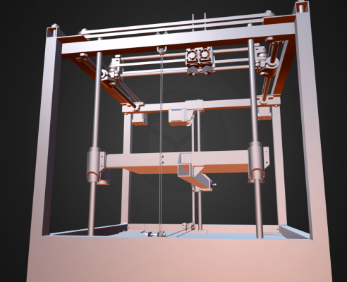
Update: Revised Model uploaded to Sketchfab. See it in 3D here at the link below.
Coffee Core4 Update1 Overview
Edited 2 time(s). Last edit at 03/10/2016 06:30PM by realthor.
RepRap Lander concept on Concept Forge
RepRap Lander concept on RepRap Forums
My Things, mostly experimental stuff
Coffee Core4 Update1 Overview
Edited 2 time(s). Last edit at 03/10/2016 06:30PM by realthor.
RepRap Lander concept on Concept Forge
RepRap Lander concept on RepRap Forums
My Things, mostly experimental stuff
|
Re: Coffeetable CoreXY:: new build :: small apartment rep-strap solutions March 14, 2016 09:19PM |
Registered: 9 years ago Posts: 1,035 |
This is the last revision before I start putting this repstrap together.
I believe I have designed about everything I need (minus extruders) and unless I stumble upon some mistake or some omission of sorts I will live with this.
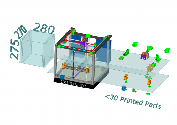
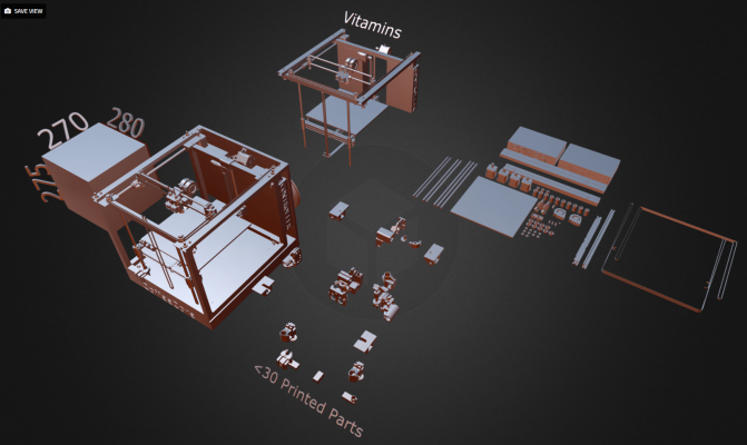
Below you can see a pic of the whole CoffeeCore printer (center), printing volume (left) and all the printed parts in a "floating" view on the right, in their respective layer. They are at the same position as if they would be mounted on the printer, but without all the rest for a better understanding and view:
>>>>>>>>>> And a link to the Sketchfab where you can see the STL in 3D and can navigate around each individual 3D printed part. <<<<<<<<<<
Edited 2 time(s). Last edit at 03/15/2016 06:41AM by realthor.
RepRap Lander concept on Concept Forge
RepRap Lander concept on RepRap Forums
My Things, mostly experimental stuff
|
Re: Coffeetable CoreXY:: new build :: small apartment rep-strap solutions March 17, 2016 07:56PM |
Registered: 9 years ago Posts: 1,035 |
Never underestimate the amount of errors that can sneak in such a complex design  ... I started building the frame and realized the coffee table's headboard is not going to make a good base to which the steel frame to be bolted, especially that the whole lower Z is dependent on this very structure to hold the screws. So away it went and until I get some heavy duty plywood I'll use some harder board I've found around and cut it to size.
As a consequence of having a much thinner board now I have also moved the most of the visible Z under the base platform for a cleaner look (you can see that easiest in the 3D view at Sketchpad - link in the post above). I really like it the way it turned out. I have a design for a complete non-repstrap build (on sketchfab too, under my profile), but I will take that one another time.
I am now almost done with all the details, and have most of the parts, except electronics and a silicone heater (maybe some more, but unless I start the build i'll never figure it out just from the design).
Anyway, below is a spoiler alert of what you will find on Sketchfab if you follow the link above:
Edited 1 time(s). Last edit at 03/18/2016 05:09AM by realthor.
RepRap Lander concept on Concept Forge
RepRap Lander concept on RepRap Forums
My Things, mostly experimental stuff
 ... I started building the frame and realized the coffee table's headboard is not going to make a good base to which the steel frame to be bolted, especially that the whole lower Z is dependent on this very structure to hold the screws. So away it went and until I get some heavy duty plywood I'll use some harder board I've found around and cut it to size.
As a consequence of having a much thinner board now I have also moved the most of the visible Z under the base platform for a cleaner look (you can see that easiest in the 3D view at Sketchpad - link in the post above). I really like it the way it turned out. I have a design for a complete non-repstrap build (on sketchfab too, under my profile), but I will take that one another time.
I am now almost done with all the details, and have most of the parts, except electronics and a silicone heater (maybe some more, but unless I start the build i'll never figure it out just from the design).
Anyway, below is a spoiler alert of what you will find on Sketchfab if you follow the link above:
Edited 1 time(s). Last edit at 03/18/2016 05:09AM by realthor.
RepRap Lander concept on Concept Forge
RepRap Lander concept on RepRap Forums
My Things, mostly experimental stuff
|
Re: Coffeetable CoreXY:: new build :: small apartment rep-strap solutions March 24, 2016 01:58PM |
Registered: 9 years ago Posts: 1,035 |
New updated version uploaded to Sketchfab. Lots of modifications as I continue with the build (reacting to the errors or opportunities for improvement) and sourcing of the parts.
Some of the modifications:
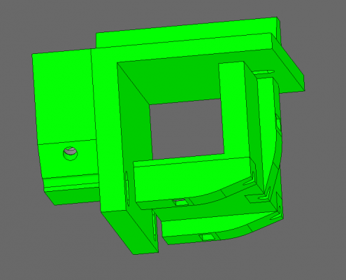
New Y Rods Ends clamps:
- two-piece square tube clamps instead of single piece (prevents issues with non-perfect prints)
- I have applied the same two-piece square clamp to the Z-motor mount:
- special centering Y Rod collars that use 3 screws to center the rod (and help with aligning all rods to be parallel)
New Y carriages: replaced 8mm bolt with 5mm bolt and M5 round coupler to fill tha gap to 8mm of the ID of the 608 bearings (makes for a slightly lighter assembly)
That's all I remember at this point. Make the jump over to Sketchfab for the 3D model.
Edited 1 time(s). Last edit at 03/25/2016 04:22AM by realthor.
RepRap Lander concept on Concept Forge
RepRap Lander concept on RepRap Forums
My Things, mostly experimental stuff
|
Re: Coffeetable CoreXY:: new build :: small apartment rep-strap solutions April 19, 2016 04:49PM |
Registered: 9 years ago Posts: 1,035 |
Update: I have left my previous location where I was developing the coffee table 3d printer so I will not have any more updates about it. I feel bad as I have invested much time into designing it. However there were many mistakes and I have learned a lot from them. All those lessons learned and the fact that I was quite unhappy with a non-reproducible 3D printer have led me to the new design, a 3D printer that is VERY forgiving with frame errors, PrintBed errors and so on. I wanted a printer anybody could build with a hacksaw and a cordless drill (and a 3D printer for the 3d printed parts of course).
Nevertheless this will be the subject of a future NEW THREAD because I am again on the road with no means to build it quickly and report /improve. So, before closing this thread, here's a quick peek at it:
There are a bunch of features that help with imperfect construction:
- the tubes will be bolted together in "nodes" that rely on the flatness of the tubing sides (by factory) rather than the cuts;
- the holes for the frame will be done with a 3D printed guide (go on thingiverse, I have pictures there of the tool), so I am pretty confident the frame can be made pretty square to start with;
- after the frame is up all the plastic parts are to be mounted on the frame using square tube clamps that can slide along the tubes to allow the first rough alignment;
- after the initial eye-ball+carpenter square+bubble+etc, the finer/sub-mm alignment will be done via the 3(4?)-points-collars that are mounted at the ends of each Y rod. One can correct to perfection the horizontal level (parallelism of the XY plane) and also the squareness of the X and Y rods;
- the Z rods' upper ends are to be inserted in 10mm holes in metal so some drill bit run of is to be expected, so the holes will not be perfect. In order to have the Z rods perfectly vertical the lower ends of the rods will not reach into some fixed plastic holder but in a larger hole in a plastic receiving part that will be filled with resin after the rods would have been calibrated via the same 3(4?)-point-adjustment-collar (see that also on thingiverse)
- on the Z side with two rods, having those two rods lined up perfectly is a requirement in most printers. In this design the linear bearings' blocks have some features that can take a lot of displacement and the T(ee) of the support of the bed will still be a perfectly square T(ee).
All these can be seen from the Sketchfab 3D model and also from the pictures I've uploaded to thingiverse.
Basically I want to be able to build this with a drill, a hacksaw and another printer of course.
NOTE: unless I get some tools and the parts I need so I can build my machine I will not open a new thread. So until then ... wish me luck staying in one place for enough time to do that
Edited 3 time(s). Last edit at 04/19/2016 05:00PM by realthor.
RepRap Lander concept on Concept Forge
RepRap Lander concept on RepRap Forums
My Things, mostly experimental stuff
Nevertheless this will be the subject of a future NEW THREAD because I am again on the road with no means to build it quickly and report /improve. So, before closing this thread, here's a quick peek at it:
There are a bunch of features that help with imperfect construction:
- the tubes will be bolted together in "nodes" that rely on the flatness of the tubing sides (by factory) rather than the cuts;
- the holes for the frame will be done with a 3D printed guide (go on thingiverse, I have pictures there of the tool), so I am pretty confident the frame can be made pretty square to start with;
- after the frame is up all the plastic parts are to be mounted on the frame using square tube clamps that can slide along the tubes to allow the first rough alignment;
- after the initial eye-ball+carpenter square+bubble+etc, the finer/sub-mm alignment will be done via the 3(4?)-points-collars that are mounted at the ends of each Y rod. One can correct to perfection the horizontal level (parallelism of the XY plane) and also the squareness of the X and Y rods;
- the Z rods' upper ends are to be inserted in 10mm holes in metal so some drill bit run of is to be expected, so the holes will not be perfect. In order to have the Z rods perfectly vertical the lower ends of the rods will not reach into some fixed plastic holder but in a larger hole in a plastic receiving part that will be filled with resin after the rods would have been calibrated via the same 3(4?)-point-adjustment-collar (see that also on thingiverse)
- on the Z side with two rods, having those two rods lined up perfectly is a requirement in most printers. In this design the linear bearings' blocks have some features that can take a lot of displacement and the T(ee) of the support of the bed will still be a perfectly square T(ee).
All these can be seen from the Sketchfab 3D model and also from the pictures I've uploaded to thingiverse.
Basically I want to be able to build this with a drill, a hacksaw and another printer of course.
NOTE: unless I get some tools and the parts I need so I can build my machine I will not open a new thread. So until then ... wish me luck staying in one place for enough time to do that

Edited 3 time(s). Last edit at 04/19/2016 05:00PM by realthor.
RepRap Lander concept on Concept Forge
RepRap Lander concept on RepRap Forums
My Things, mostly experimental stuff
|
Re: Coffeetable CoreXY:: new build :: small apartment rep-strap solutions April 19, 2016 07:51PM |
Registered: 8 years ago Posts: 776 |
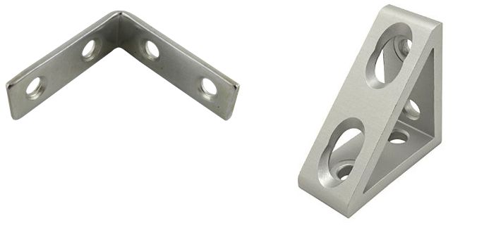
the one on the left is crap. total crap. i made a serious mistake in buying some of those. you are welcome to have them, i will never, ever use them. they are a total waste of your effort to even bother to put them in: you will waste 4 screws and simply increase the weight. basically, they bend about the right-angle point so provide absolutely no right-angle rigidity; they slide around the bolts so provide absolutely no effectiveness at joining the parts together: to get any kind of grip you have to do the bolts up so tight it almost strips the threads and they will *still* come loose at some point. does that make it clear enough how much you'd be wasting your time to use them?
in complete contrast, the one on the right is excellent.and i'd really like to know where to get it
 i am currently using these: [www.ebay.co.uk] and they are simple, low-cost, and extremely effective. the 15x15 extrusion i have them attached to, in a 420x400 square, i simply cannot bend it *at* all.
|
Re: Coffeetable CoreXY:: new build :: small apartment rep-strap solutions April 19, 2016 08:12PM |
Registered: 8 years ago Posts: 776 |
Quote
dc42
Quote
LarsK
...
Finally - Ramps + Arduino just works... It is one less unknown for your build because you can be 99% sure that whatever problem you encounter, someone else will have experienced it before...
I think it is more accurate to say that a good quality Ramps + Arduino + LCD (needed for the SD card) just works, provided you don't attach a graphical LCD or a servo (either of which will overheat the voltage regulator on the Arduino), and once you have mastered the art of setting the stepper driver pots using a voltmeter without damaging them in the process. There are posts on these forums every week from users who have overheated the Arduino 5V regulator, and from users who are having difficulty getting the motor currents right.
IMO there are fewer unknowns with a Duet, and probably by now with as SBASE too.
i have to agree with dc42, i wrote to davedavedave here [forums.reprap.org] and i recommend you read it before spending your money. i describe why the whole RAMPs concept of using "proof-of-concept" test boards only 16mm sq with a 2.5A stepper ICs into production and then expecting there not to be any problems... i just don't understand why people don't understand that.
my friend phil bought one of the very early repraps. because it was a prototype, they got those same "test" boards from the manufacturer for the stepper ICs. anyone in the industry with any experience *knows* that you *do not* put those into production.
so he would run the printer for 5 minutes, and of course the stepper modules would overheat, causing the motors to just... randomly stop for a few seconds to cool down. and this is in the middle of a print!
so, wondering about this, he read up on the datasheet and was absolutely astounded at the sheer incompetence of the people who'd been thinking that putting 16mm square boards with a 2.5A IC on it would in any way be effective, especially when there's a ceramic insulator on the top of the ICs which PREVENTS HEAT FROM GETTING OUT EVEN WITH A HEATSINK.
so for goodness sake, realthor, get something like a Duet - it's a faster SoC anyway, it's 32-bit, the RepRapFirmware is excellent and well-designed, and i'm happy to run you through the process of configuring it to suit your corexy printer - the configs that i'm using are here: [hands.com]
anyway i see you've got a sanguinolulu, that is also based around the "let's put 2.5A ICs onto tiny PCBs so the heat can't get out" concept. i had a melzi with the mendel90 i had, and the melzi was damn good. if you're lucky you might be able to find the last few around, cheap, but you'll need a dual PSU (5V and 12V) e.g. a desktop PC "AT" style PSU. i used to print at 200mm/sec with that, and it coped fine (despite being a direct-drive printer). when you have a single PCB, the heat from the stepper ICs can distribute properly.
but, the Duet 0.8.5 is pretty damn good, *and* is good value. it even has an ethernet port and the firmware has a web interface with proper controls on it like those you get on pronterface. you can create your own macros, drop them on the microsd card, and you get the same thing as the pronterface "custom commands", except of course much more sophisticated because you can do any g-codes.
i love that i can now sit with my laptop on wifi, no longer connected by a USB cable, and play around. makes life really easy.
p.s. i do have a rambo v1.2g you're welcome to, i had to create a separate voltage-divider circuit, there's a bug in the 1.2g design. if you're happy to pay postage and packing you can have it.
Edited 1 time(s). Last edit at 04/19/2016 08:14PM by lkcl.
|
Re: Coffeetable CoreXY:: new build :: small apartment rep-strap solutions April 20, 2016 03:19AM |
Registered: 9 years ago Posts: 1,035 |
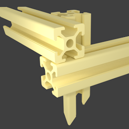
@lkcl: Regarding the angles, I am using a "scout-tower"-like node configuration so I corner brackets will be difficult to adapt. They are basically intended for extrusions that connect head-on-head at the nodes. I am using this style of node:
, which makes each member a "bracket" for the next. It is stable enough I hear. I am thinking of diagonal braces better than the brackets, maybe even cable-based, but that after I would have seen it during printing ...which could be some time from now as I am in yet another BT and left most of my previous parts/etc at the maker space.
Regarding the Duet, you are right and I completely agree. It's just that this printer is very experimental and I need something cheap to do the testing/etc. If it proves to be ok then I will upgrade it or build another one and give it to the maker space in the area where I will be for the next couple of months.
Thanks for chiming in.
RepRap Lander concept on Concept Forge
RepRap Lander concept on RepRap Forums
My Things, mostly experimental stuff
, which makes each member a "bracket" for the next. It is stable enough I hear. I am thinking of diagonal braces better than the brackets, maybe even cable-based, but that after I would have seen it during printing
 ...which could be some time from now as I am in yet another BT and left most of my previous parts/etc at the maker space.
Regarding the Duet, you are right and I completely agree. It's just that this printer is very experimental and I need something cheap to do the testing/etc. If it proves to be ok then I will upgrade it or build another one and give it to the maker space in the area where I will be for the next couple of months.
Thanks for chiming in.
RepRap Lander concept on Concept Forge
RepRap Lander concept on RepRap Forums
My Things, mostly experimental stuff
|
Re: Coffeetable CoreXY:: new build :: small apartment rep-strap solutions April 20, 2016 10:51AM |
Registered: 8 years ago Posts: 776 |
Quote
realthor
@lkcl: Regarding the angles, I am using a "scout-tower"-like node configuration so I corner brackets will be difficult to adapt. They are basically intended for extrusions that connect head-on-head at the nodes. I am using this style of node:
oooo intriguing. ok well then Edvardas recommended another possible technique you might like, if you have a drill, basically you put a hole through the extrusion... normally you would put the bolt into the self-tapping end, but i see no reason why you shouldn't just drill straight through *all* the extrusions - in this case in three places (so 6 holes in total)... could you get away with 2 places (only 4 holes)... mmmm.... probably not. oh i see later down you're in a makerspace, yeah if they have a bench-mounted drill use that, should be really easy, and three-hole mounted should be really really strong, you can slide a hex-nut into the rails on one side, and an allen-key bolt through to the other extrusion, get good grip that way, maybe have to overdrill a little bit to get the allen-key head in.
what you reckon? that way there's no brackets needed at all.
Quote
, which makes each member a "bracket" for the next. It is stable enough I hear. I am thinking of diagonal braces better than the brackets, maybe even cable-based,
no on the cables! they'll stretch. ok, if you used a ratchet system (i've seen people use hose-clamps - look up the "foamcore" 3d printer it's hilarious) then you could get enough tension, and "punggg" the cables to make sure they're all tight... i mean... it'd work... but...

the one thing you *can't* do that on is the top corexy part - that really really does have to be rigid, and it's no good thinking that plastic will do the job. you also can't put anything inside the space because, duh, the printhead's moving in it. duh. if you don't get that top rigid, your entire printer can be twisted about. easy to do: put your feet on the frame base, grab the top, and twist like a bottle-cap. you will be absolutely amazed at how much it moves, even if you've filled in all the other sides with panels, diagonal bracing or... anything else for that matter.
so please do think about that. if you do that drilling technique on every corner, it might actually be stiff enough i'd be fascinated to know if it works.
Quote
Regarding the Duet, you are right and I completely agree. It's just that this printer is very experimental and I need something cheap to do the testing/etc. If it proves to be ok then I will upgrade it or build another one and give it to the maker space in the area where I will be for the next couple of months.
Thanks for chiming in.
yehh the sanguililiolinolo-oh you have will do the job easily for testing, just don't push it so hard that you can't touch the heatsinks on the stepper ICs. back the current *right* down, find a couple of big fans and point them at those tiny boards... *sigh*...
|
Re: Coffeetable CoreXY:: new build :: small apartment rep-strap solutions April 20, 2016 10:56AM |
Registered: 8 years ago Posts: 776 |
oh, oh, before i forget, realthor, have a look in the fusebox forum. we've just been discussing methods of getting strong-enough z-upright supports, there's something called the "G&C" printer which uses aluminium L-bracket, we also had some people say that using M10 or M12 rods and quad LM10UU / LM12UU bearings (2 per side) is... a good idea, shall we say. link... link... where are ya.... ok: [forums.reprap.org]
|
Re: Coffeetable CoreXY:: new build :: small apartment rep-strap solutions April 20, 2016 03:06PM |
Registered: 9 years ago Posts: 1,035 |
Mann, this thread has been quite "dead" in interaction apart from my insisting updates for something that nobody seemed to be interested in any more hehe...it's good to see someone reviving the spirits a bit.
Ok, so before anything else I want to make a few things clear:
1) I will try square tubing first because I can't find extrusions in my area and I'd have to order from abroad (Germany most likely) which is not cheap. Moreover, I find the advantages of extrusions not necessary in the build I propose:
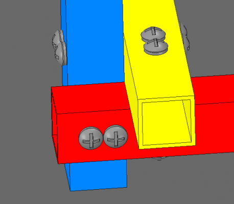
-you don't have to cut straight with my design;
- having 3 tubes at each node, with two screws per each tube-to-tube connection means 6 bolts per node, making it not only strong but also will have the covered area a bit larger than the similar situation with only one bolt per tube-to-tube connection (example below):
- you don't necessarily need the SLOT because I have the square clamp that every designed piece includes;
- you can drill by hand ALL holes (using the "TOOL drill guide" I am designing), even the holes for the Rods, the upper ends of which will go straight in metal (like Solidoodle does);
- any misalignment or drill bit runoff can be compensated by the features in the design, even by gross margins of 5mm or even more; I will demonstrate that with a video at the proper time, when I will have the machine running (can be some time until then, I have a lifestyle that doesn't have me long enough in one place and I can't drag all my stuff with me every time ...anyway ...)
I am interested in ways to make the top plane stronger. However, the Quadrap doesn't seem to need much strengthening.
Edited 3 time(s). Last edit at 04/21/2016 03:58AM by realthor.
RepRap Lander concept on Concept Forge
RepRap Lander concept on RepRap Forums
My Things, mostly experimental stuff
|
Re: Coffeetable CoreXY:: new build :: small apartment rep-strap solutions April 21, 2016 07:46AM |
Registered: 8 years ago Posts: 776 |
Quote
realthor
Mann, this thread has been quite "dead" in interaction apart from my insisting updates for something that nobody seemed to be interested in any more hehe...it's good to see someone reviving the spirits a bit.

1) I will try square tubing first because I can't find extrusions in my area and I'd have to order from abroad (Germany most likely) which is not cheap. Moreover, I find the advantages of extrusions not necessary in the build I propose:
-you don't have to cut straight with my design;
- having 3 tubes at each node, with two screws per each tube-to-tube connection means 6 bolts per node, making it not only strong but also will have the covered area a bit larger than the similar situation with only one bolt per tube-to-tube connection (example below):
[attachment 76789 screenshot.568.png]
[/quote]
mmm... 6 bolts won't help, they're too close together to make any difference (if you're thinking they might stop rotation for example), they might in fact just weaken the metal, instead you would be better off with a larger-diameter set of 3 bolts.
the only thing about square bar - which is great because you can get it from a hardware store - is that you'd end up bending it - i can guarantee that. to stop that you could put some (perfectly-measured!) tubular inset inside [1]. make the ID just enough to fit the chosen bolts, and they will stop the bar from crushing. if you don't tighten them up enough to crush the bars, the bars will be loose. if you tighten them enough to make them not move, they'll crush for absolute certain.
one other thing: take care with how accurately you drill those holes, they'd be better off slightly close. also.... thinking about it....you're going to get a slight amount of twisting. you want to make absolutely absolutely sure that the alignment of the bars is such that the left side twist cancels out against the right-side twist, likewise up-twist against down-twist. so for the left side for example the blue bar should be on the LEFT, and for the right side the blue bar should be on the RIGHT.
Quote
I am interested in ways to make the top plane stronger. However, the Quadrap doesn't seem to need much strengthening.
ok well if you double-up the bars (even with a single piece of 50mm length) then you could use those corner-braces. but, i think, really, the whole idea of doing those triple-joined bars, i think it'll be really strong and stiff *without* corner braces... as long as you make sure the arrangement is mirrored so that twists cancel out.
[1] update: or, get some square, solid bar that's the same OD as the ID of the tube, cut it, put it in the end, *then* drill... through the whole lot.
Edited 1 time(s). Last edit at 04/21/2016 07:53AM by lkcl.
|
Re: Coffeetable CoreXY:: new build :: small apartment rep-strap solutions April 21, 2016 08:46AM |
Registered: 9 years ago Posts: 1,035 |
Quote
lkcl
mmm... 6 bolts won't help, they're too close together to make any difference (if you're thinking they might stop rotation for example), they might in fact just weaken the metal, instead you would be better off with a larger-diameter set of 3 bolts.
The initial design was for steel square tubing. With Aluminum you might be right but two holes closer to the lateral walls of the tubing will prevent crushing it if tightened and they will ensure squareness (the way I am thinking about it). I'll think about it.
Quote
lkcl
the only thing about square bar - which is great because you can get it from a hardware store - is that you'd end up bending it - i can guarantee that. to stop that you could put some (perfectly-measured!) tubular inset inside [1]. make the ID just enough to fit the chosen bolts, and they will stop the bar from crushing. if you don't tighten them up enough to crush the bars, the bars will be loose. if you tighten them enough to make them not move, they'll crush for absolute certain.
Funny thing this was the exact plan just that i still had two of them and the tubular inset was actually a hex coupler that I would cut to length. But I figured that if I place the holes near the walls then I will not crush the tubes. Original Quadrap used a single M5 bolt in an M6 hole to allow for some adjustment and it didn't crush the tube. Of course some large washers were used to spread the pressure.
If one wants to stop crushing the tube while fastening the bolt any assortment of nuts and washers that you can get inside to fill the whole gap can be attempted. I just don't think one will ever get to the "perfect" inside wall-to-wall distance. But consider this: first you don't tighten the bolts too much, just enough to assemble the frame and make it square. Then you will have 3 tubes laying against each other so they will prevent much crushing if you tighten all the bolts at the same time, gradually increasing the force. All those walls in a close area will provide enough resistance to prevent crushing. Moreover, with two bolts per tube-to-tube connection, being near the walls, the force needed for crushing would be quite high.
Quote
lkcl
one other thing: take care with how accurately you drill those holes, they'd be better off slightly close.
I will be drilling the holes using a jig, a tool with some sort of drill guide bushings so I guess the holes will end up pretty accurate.
Quote
lkcl
also.... thinking about it....you're going to get a slight amount of twisting. you want to make absolutely absolutely sure that the alignment of the bars is such that the left side twist cancels out against the right-side twist, likewise up-twist against down-twist. so for the left side for example the blue bar should be on the LEFT, and for the right side the blue bar should be on the RIGHT.
I don't quite get this but the arrangement in the design is about the only one that I find acceptable for the configuration I have created.
Edited 1 time(s). Last edit at 04/21/2016 08:46AM by realthor.
RepRap Lander concept on Concept Forge
RepRap Lander concept on RepRap Forums
My Things, mostly experimental stuff
|
Re: Coffeetable CoreXY:: new build :: small apartment rep-strap solutions April 22, 2016 09:20AM |
Registered: 8 years ago Posts: 776 |
Quote
realthor
If one wants to stop crushing the tube while fastening the bolt any assortment of nuts and washers that you can get inside to fill the whole gap can be attempted. I just don't think one will ever get to the "perfect" inside wall-to-wall distance. But consider this: first you don't tighten the bolts too much, just enough to assemble the frame and make it square. Then you will have 3 tubes laying against each other so they will prevent much crushing if you tighten all the bolts at the same time, gradually increasing the force. All those walls in a close area will provide enough resistance to prevent crushing. Moreover, with two bolts per tube-to-tube connection, being near the walls, the force needed for crushing would be quite high.
nope. so, you don't believe me. what i suggest you now do is, actually try it, and can i suggest that you try it *now*... before proceeding further with any design work. washers will work but will be a pain to fit in. [edit: actually... they won't. washers aren't straight and flat, they tend to be banged out a bit inaccurately. they'll be utterly useless as they'll compress... and that means the edges of the bar will be crushed]. a solid bar of the right diameter will be easiest. doesn't have to be long. if it doesn't quite fit, hit it into the end with a hammer - that would actually be very very good, that it was so tight it wasn't moving.
basically i know that they will either crush or they will be loose, and in fact probably both, because i've tried this before. the worst bit is, you crush the damn thing, then think, "hmm i just need to loosen it up a bit" and of course it's too late, the metal's crushed. now you've just crushed the last bar on the frame, you have to take it out, and that's a bitch of a disassembly job, and then you find that to get the tension right a 2nd time you have to crush them *even more*....
...and now your frame's completely f*****d.
two bolts or one bolt will make absolutely f***-all difference and be a waste of extra bolts. even if you offset the bolts close to the edge, so as to use the edge to avoid crushing, it still won't work as effectively as filling in the end with a solid piece of metal.
there really is a good reason for using that aluminium extrusion: it's designed to be strong even when you try to crush it.
Quote
Quote
lkcl
also.... thinking about it....you're going to get a slight amount of twisting. you want to make absolutely absolutely sure that the alignment of the bars is such that the left side twist cancels out against the right-side twist, likewise up-twist against down-twist. so for the left side for example the blue bar should be on the LEFT, and for the right side the blue bar should be on the RIGHT.
I don't quite get this but the arrangement in the design is about the only one that I find acceptable for the configuration I have created.
the bolts will be able to rotate. the bolts are under TENSION.... but they're off-centre aren't they, because they're not on the EDGES of the bar, they're in the MIDDLE. and of course you can't drill through the edges of the bar, the bolts would drop out.
so, as you tension the bolts, they'll cause rotation of the bars. you want that rotational force to EQUALISE. and to do that, you need the bars to be mirrored.
you'll need to make sure that the arrangement shown is the same on *ALL* twelve bars.
clear?
Edited 1 time(s). Last edit at 04/22/2016 09:22AM by lkcl.
|
Re: Coffeetable CoreXY:: new build :: small apartment rep-strap solutions April 22, 2016 03:37PM |
Registered: 9 years ago Posts: 1,035 |
Yes, you start to make some sense now  ... joking, I understand a bit more from this second explanation.
I got it now what you meant by a solid bar of the right diameter inside the square tube, preferably having the bolts go through it so that the whole thing is like a solid piece in that section. But I wonder if I can get anywhere the exact dimensions of a solid bar (square preferably) so that it fits inside the tube.
My initial idea was to use hex couplers cut to the exact inside height of the tube so that I screw the bolt right through it. I think I should come back to that idea which I think would be easier.
"there really is a good reason for using that aluminium extrusion: it's designed to be strong even when you try to crush it." <- I agree. However, I will insist for some more time on alu square tubing and try to apply some hacks to make it work, like the hex coupler/solid bar one.
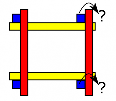
The 12 tubes arrangement issue is not that clear I'm afraid. I need to understand your pov before I "believe" . Is your observation in line with the sketch below? Is the columns arrangement below (view from top) what you meant?
Regards.
Edited 1 time(s). Last edit at 04/22/2016 03:49PM by realthor.
RepRap Lander concept on Concept Forge
RepRap Lander concept on RepRap Forums
My Things, mostly experimental stuff
 ... joking, I understand a bit more from this second explanation.
I got it now what you meant by a solid bar of the right diameter inside the square tube, preferably having the bolts go through it so that the whole thing is like a solid piece in that section. But I wonder if I can get anywhere the exact dimensions of a solid bar (square preferably) so that it fits inside the tube.
My initial idea was to use hex couplers cut to the exact inside height of the tube so that I screw the bolt right through it. I think I should come back to that idea which I think would be easier.
"there really is a good reason for using that aluminium extrusion: it's designed to be strong even when you try to crush it." <- I agree. However, I will insist for some more time on alu square tubing and try to apply some hacks to make it work, like the hex coupler/solid bar one.
The 12 tubes arrangement issue is not that clear I'm afraid. I need to understand your pov before I "believe"
 . Is your observation in line with the sketch below? Is the columns arrangement below (view from top) what you meant?
Regards.
Edited 1 time(s). Last edit at 04/22/2016 03:49PM by realthor.
RepRap Lander concept on Concept Forge
RepRap Lander concept on RepRap Forums
My Things, mostly experimental stuff
|
Re: Coffeetable CoreXY:: new build :: small apartment rep-strap solutions April 22, 2016 09:34PM |
Registered: 11 years ago Posts: 1,049 |
The original coffee table stand was a welded steel frame
probably jigged up square and butt welded solid
That made it a ready made rigid square frame
but you are way away from that
The crossed square tubing with no braces not very sound
but
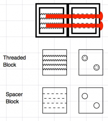
how about spacers and threaded blocks
Prevents crushing and provides threaded fastener
could be aluminum or printed

probably jigged up square and butt welded solid
That made it a ready made rigid square frame
but you are way away from that
The crossed square tubing with no braces not very sound
but
how about spacers and threaded blocks
Prevents crushing and provides threaded fastener
could be aluminum or printed

|
Re: Coffeetable CoreXY:: new build :: small apartment rep-strap solutions April 23, 2016 06:10AM |
Registered: 8 years ago Posts: 776 |
whew.Quote
realthor
Yes, you start to make some sense now... joking, I understand a bit more from this second explanation.
Quote
I got it now what you meant by a solid bar of the right diameter inside the square tube, preferably having the bolts go through it so that the whole thing is like a solid piece in that section. But I wonder if I can get anywhere the exact dimensions of a solid bar (square preferably) so that it fits inside the tube.
+/-0.1mm is fine - a bit of crush is.. not really okay but it's okay . using (i should say *needing*) a hammer to bash the solid pieces in is okay (best). +/-0.5mm you'll get problems. aluminium, once it's bent, you can never bend it back again. it's a bit weird like that: when it bends it actually fractures and loses a lot of its strength. even just one bend beyond its elasticity point and that's it, chuck it.
Quote
My initial idea was to use hex couplers cut to the exact inside height of the tube so that I screw the bolt right through it. I think I should come back to that idea which I think would be easier.
good idea... except see below. you want overlap, and you want the convenience of being able to not fiddle about. think about the assembly process a bit, step-by-step. twelve sets of hex-couplers per corner?? solid blocks 40x16x16 (if the ID is 16mm) would be much better, yes?
Quote
"there really is a good reason for using that aluminium extrusion: it's designed to be strong even when you try to crush it." <- I agree. However, I will insist for some more time on alu square tubing and try to apply some hacks to make it work, like the hex coupler/solid bar one.
cozmicray sent some great ideas
Quote
The 12 tubes arrangement issue is not that clear I'm afraid. I need to understand your pov before I "believe".
well, you don't have to "believe" - you can model it, or make a test rig, and find out. join two pieces together, put one bar in a vice and then twist the upright (like a lever). if it moves, it ain't good enough!
Quote
Is your observation in line with the sketch below? Is the columns arrangement below (view from top) what you meant?
[attachment 76923 screenshot.569.png]
Regards.
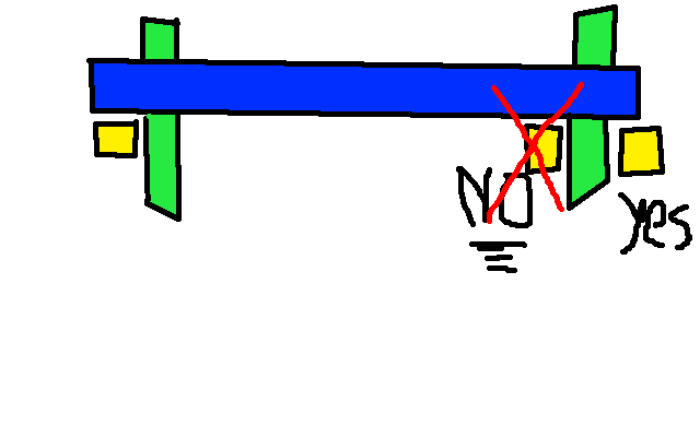
NO. do NOT arrange the tubes like they're shown in that picture. make DAMN SURE that the blue one is where the question-mark is. i'm not sure why it's not clear from what i drew. i put a cross through the one that will cause problems, as well as put the word "NO" next to it. no means "no". yes means "yes".
... actually... now that i think about it, having seen that more complete diagram, i believe i may have been over-cautious. the red bar on the left, when you tension everything up, will cause the yellow bars to rotate inwards. *however*.... the right-hand red bar will stop that, no matter which side it's placed. personally though i'd still put the red bars both on the outside (not one outside, one inside).
also, if you've got solid inserts to a depth of... what's the extrusion outer dimensions? 20x20? so if you've got solid pieces 40mm long (or just a bit more) they'll actually overlap, create in effect 3 solid bars right where you need them to be, and you should be fine.
|
Re: Coffeetable CoreXY:: new build :: small apartment rep-strap solutions April 23, 2016 09:01AM |
Registered: 9 years ago Posts: 1,035 |
Ok, thanks for pushing me, please be understanding too  , I am an insisting guy but have very little practical experience.
The problem with the solid/threaded blocks is that they have to be machined and taped, which I can't do at 0.1 tolerances (have no drill press/milling machine and no hacker space in this new location, just a vice, hacksaw, cordless drill, the usual).
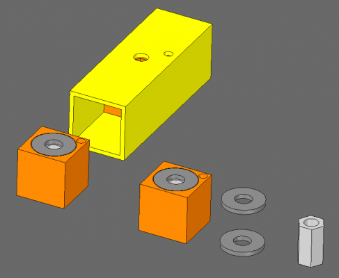
With Hex coupler it's quite easy to have it cut a bit over the length and simply file it until it can be inserted with a bit of push in the tube up to the holes. Yes with my two bolts per connection it will be quite a number of hex couplers but I might resort to a combination of what @cozmicray suggests with the printed threaded block and my Hex Coupler solution: namely I would print a block with a space to insert a single hex coupler and an accompanying threaded hole near the tube's wall, to take advantage of the wall compression strength to use as a helper. I would still like to use washers to spread the loadonto the plastic... I just don't know to what tolerance I can get the stack (washer+hex -cut to length and filed - + another washer).
Here's a combination of the above suggestions, the way I understood it:
I can also move with very little modification the blue columns (blue) tubes outside of the red one from the sketch above, in the place of the question marks, as it has been suggested.
RepRap Lander concept on Concept Forge
RepRap Lander concept on RepRap Forums
My Things, mostly experimental stuff
 , I am an insisting guy but have very little practical experience.
 The problem with the solid/threaded blocks is that they have to be machined and taped, which I can't do at 0.1 tolerances (have no drill press/milling machine and no hacker space in this new location, just a vice, hacksaw, cordless drill, the usual).
With Hex coupler it's quite easy to have it cut a bit over the length and simply file it until it can be inserted with a bit of push in the tube up to the holes. Yes with my two bolts per connection it will be quite a number of hex couplers but I might resort to a combination of what @cozmicray suggests with the printed threaded block and my Hex Coupler solution: namely I would print a block with a space to insert a single hex coupler and an accompanying threaded hole near the tube's wall, to take advantage of the wall compression strength to use as a helper. I would still like to use washers to spread the loadonto the plastic... I just don't know to what tolerance I can get the stack (washer+hex -cut to length and filed - + another washer).
Here's a combination of the above suggestions, the way I understood it:
I can also move with very little modification the blue columns (blue) tubes outside of the red one from the sketch above, in the place of the question marks, as it has been suggested.
RepRap Lander concept on Concept Forge
RepRap Lander concept on RepRap Forums
My Things, mostly experimental stuff
|
Re: Coffeetable CoreXY:: new build :: small apartment rep-strap solutions April 23, 2016 09:54AM |
Registered: 11 years ago Posts: 5,780 |
I don't get it. You guys will use 3D printed parts for the most inappropriate things, but when it comes to something as simple as the square plugs to fit the tubing, all of a sudden you need machined metal? How about just measuring the tube and 3D printing a solid piece to fit? Tap it in with a rubber mallet then drill your holes and bolt the whole thing together.
For that matter, a piece of wood should work fine, too.
Ultra MegaMax Dominator 3D printer: [drmrehorst.blogspot.com]
For that matter, a piece of wood should work fine, too.
Ultra MegaMax Dominator 3D printer: [drmrehorst.blogspot.com]
Sorry, only registered users may post in this forum.
