My 350x350mm CoreXY design
Posted by Dalius98
|
My 350x350mm CoreXY design January 01, 2016 05:40PM |
Registered: 8 years ago Posts: 67 |
Hello again and happy new year everyone! You might remember me from my recent topic in the Mechanics part of the forum, but I think it is time to move over to here 
So, I've finally got some aluminium extrusions (which happen to be made to some odd standard) and decided it was time to rework my "blueprints", this time to the proper dimensions... But let's start from the beginning.
This will be the main topic covering all my questions, as well as construction related updates, files and photos. I plan to release the 3D drawing of the machine, along with anything else you might request, but honestly, half of the parts are salvaged from other equipment and not readily available for purchase. Furthermore, this design is not very "economical", nor is it very good (probably), but if you want to build something similar - go ahead
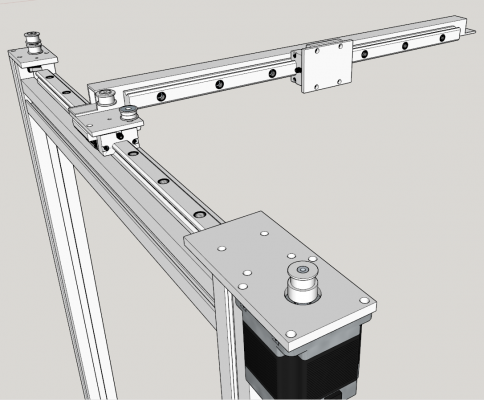
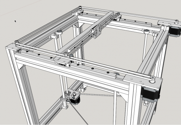
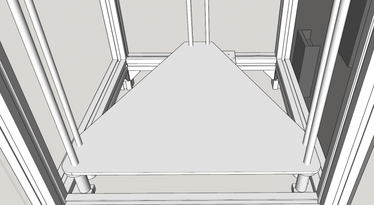
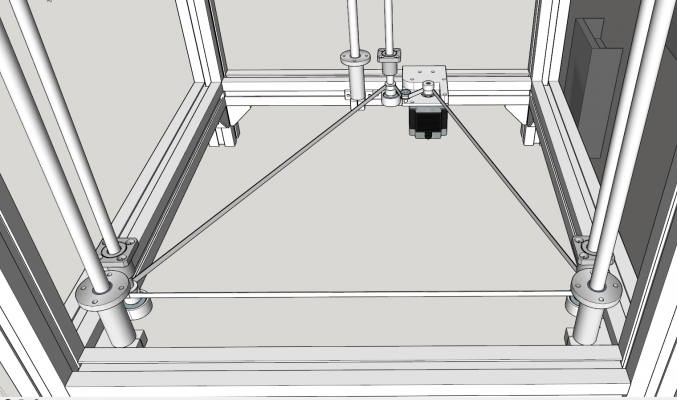
This is the current state of my design, if you want to see what I am aiming for - visit this link
In order to move forward I need to decide on two things - how to clamp the belts and what should be the size of the X carriage assembly.
As for the belt clamp... if I just clamp them directly on the X carriage plate (similar to this) I can only tension them by hand force (which might not be enough), but if I go for some screw tensioner or some other design, it adds thickness to the X carriage and offsets the belt path a bit (so I will need to offset the idler pulleys on the Y carriages accordingly). Either way, I need to decide on what I'll use before I can proceed. Any tips are welcome.
And as for the X carriage itself... I need to know the dimensions of the hot end plus all the fans and maybe other equipment positioned on it, so I can leave enough empty space for it as to use all available rail length... So, what "equipment" should I position on the X carriage? I see some designs include one or two fans blowing on the freshly extruded filament (such as this "thing" posted in the G&C printer topic), others have a sensor for bed tramming, etc.
I guess the additional fans are there to cool the extruded plastic when printing small parts, so as to not print on the still soft layers, and with the higher print speeds of a coreXY design this might be even more noticeable. Could you link me to some good design so I could make out some dimensions? And if I ever decide to go for a direct type of extruder, I should leave some space for it too... Any tips?
On a side note, I would like to consult on one thing... Generally, it's the length of the stepper motor (along with it's NEMA mounting standard) that defines it's torque, right? I mean, I know there are things like Amperage, Inductance and so on, but the motors I have on hand are made on a special order (salvaged from some equipment working with money (not an ATM, but I guess it wasn't a printer either ), and the specific part number is not available in manufacturers spec sheets. The closest I can get is the same identifying letters with different numbers meaning the length of the motor. The motor in the spec sheets is 4.7V 1.5A 5200g/cm (56mm length), and the one I have is 5.4V 1.5A and ~69mm length - generally it should be more powerful, right? Any idea how much?
Anyway, I have another three motors that are in the spec sheets, and they have 7200g/cm of torque, so I could use those if the other ones prove to be a lot weaker... But I have a CNC router planned, for which I'd like to have some more powerful motors...
Edited on 01.03 - Spent a few hours putting everything in their places... A few more evenings like this and I can start thinking about the next step.
Edited 1 time(s). Last edit at 01/02/2016 05:48PM by Dalius98.

So, I've finally got some aluminium extrusions (which happen to be made to some odd standard) and decided it was time to rework my "blueprints", this time to the proper dimensions... But let's start from the beginning.
This will be the main topic covering all my questions, as well as construction related updates, files and photos. I plan to release the 3D drawing of the machine, along with anything else you might request, but honestly, half of the parts are salvaged from other equipment and not readily available for purchase. Furthermore, this design is not very "economical", nor is it very good (probably), but if you want to build something similar - go ahead

This is the current state of my design, if you want to see what I am aiming for - visit this link
In order to move forward I need to decide on two things - how to clamp the belts and what should be the size of the X carriage assembly.
As for the belt clamp... if I just clamp them directly on the X carriage plate (similar to this) I can only tension them by hand force (which might not be enough), but if I go for some screw tensioner or some other design, it adds thickness to the X carriage and offsets the belt path a bit (so I will need to offset the idler pulleys on the Y carriages accordingly). Either way, I need to decide on what I'll use before I can proceed. Any tips are welcome.
And as for the X carriage itself... I need to know the dimensions of the hot end plus all the fans and maybe other equipment positioned on it, so I can leave enough empty space for it as to use all available rail length... So, what "equipment" should I position on the X carriage? I see some designs include one or two fans blowing on the freshly extruded filament (such as this "thing" posted in the G&C printer topic), others have a sensor for bed tramming, etc.
I guess the additional fans are there to cool the extruded plastic when printing small parts, so as to not print on the still soft layers, and with the higher print speeds of a coreXY design this might be even more noticeable. Could you link me to some good design so I could make out some dimensions? And if I ever decide to go for a direct type of extruder, I should leave some space for it too... Any tips?
On a side note, I would like to consult on one thing... Generally, it's the length of the stepper motor (along with it's NEMA mounting standard) that defines it's torque, right? I mean, I know there are things like Amperage, Inductance and so on, but the motors I have on hand are made on a special order (salvaged from some equipment working with money (not an ATM, but I guess it wasn't a printer either
 ), and the specific part number is not available in manufacturers spec sheets. The closest I can get is the same identifying letters with different numbers meaning the length of the motor. The motor in the spec sheets is 4.7V 1.5A 5200g/cm (56mm length), and the one I have is 5.4V 1.5A and ~69mm length - generally it should be more powerful, right? Any idea how much?
 Anyway, I have another three motors that are in the spec sheets, and they have 7200g/cm of torque, so I could use those if the other ones prove to be a lot weaker... But I have a CNC router planned, for which I'd like to have some more powerful motors...
Edited on 01.03 - Spent a few hours putting everything in their places... A few more evenings like this and I can start thinking about the next step.
Edited 1 time(s). Last edit at 01/02/2016 05:48PM by Dalius98.
|
Re: My 350x350mm CoreXY design January 02, 2016 08:43AM |
Registered: 9 years ago Posts: 346 |
Hey,
1) It is OK with just tensioning the belts by hand and locking them.
2) You can just google the dimensions of a e3d hotend. Or download one model on thingiverse or grabcad.
About fans; If you plan to use a heated bed and print in ABS then you cannot (not optional) blow air on the extruded plastic - As such, you will only need to cool the heatsink on the hotend (the ribs) and do that with a ducting so no air is diverted onto the print. If you want to print PLA then you can optionally install a fan to blow on the extruded plastic (it will allow you to print faster and better).
3) The steppers you have on hand will work fine - Actually they are pretty overpowered. You will not be powering them with more than 1A anyways - Even less then that should be enough for your purpose. I also use Minbea for my z axis - If you have not yet sorted out the connection this photo may help.The one you have (23LM-C710-04) is in the big class . They are maybe stronger then your alternative but you can measure the phase resistance with an ohm-meter to confirm that.
I am no expert on steppers, actually my electronic skills are pretty poor, but you should be aware of the following potential problems with you choice of motors:
a) They are big - Nema 23 is more difficult to implement than Nema 17 - And yours are almost the biggest you can get in the 23 series.
b) There are some stepper voodoo which may give you a headache. Mainly for the extruder. If you don't use the normal Nema17 long on the extruder you may get strange problems with retraction problems and motor grinding filament.
|
Re: My 350x350mm CoreXY design January 02, 2016 10:01AM |
Registered: 8 years ago Posts: 67 |
Quote
LarsK
Hey,
1) It is OK with just tensioning the belts by hand and locking them.
2) You can just google the dimensions of a e3d hotend. Or download one model on thingiverse or grabcad.
About fans; If you plan to use a heated bed and print in ABS then you cannot (not optional) blow air on the extruded plastic - As such, you will only need to cool the heatsink on the hotend (the ribs) and do that with a ducting so no air is diverted onto the print. If you want to print PLA then you can optionally install a fan to blow on the extruded plastic (it will allow you to print faster and better).
Thanks for the answer. I do have a model of some hotend, but I was more concerned about the additional equipment such as the aforementioned fans, but I see they aren't necessary. This, along with the simple belt clamp simplifies things

Quote
LarsK
3) The steppers you have on hand will work fine - Actually they are pretty overpowered. You will not be powering them with more than 1A anyways - Even less then that should be enough for your purpose. I also use Minbea for my z axis - If you have not yet sorted out the connection this photo may help.The one you have (23LM-C710-04) is in the big class . They are maybe stronger then your alternative but you can measure the phase resistance with an ohm-meter to confirm that.
I am no expert on steppers, actually my electronic skills are pretty poor, but you should be aware of the following potential problems with you choice of motors:
a) They are big - Nema 23 is more difficult to implement than Nema 17 - And yours are almost the biggest you can get in the 23 series.
b) There are some stepper voodoo which may give you a headache. Mainly for the extruder. If you don't use the normal Nema17 long on the extruder you may get strange problems with retraction problems and motor grinding filament.
Whoa, your Z motor is TINY
 Anyway, I am aware my motors are a bit big and not often seen in 3D printers, but the rest of the build is equally overkill (such as 40x40 extrusions, linear guides, etc.), and I'd rather have half of the power to spare, than buy weaker ones...
But I can understand your concerns about using them in extruder - a powerful motor is unlikely to skip steps when obstruction occurs, and will grind the filament. Can I just run it under a lower current, or will that have other negative aspects? And what retraction problems are we talking about?
|
Re: My 350x350mm CoreXY design January 02, 2016 12:06PM |
Registered: 9 years ago Posts: 346 |
Quote
Dalius98
But I can understand your concerns about using them in extruder - a powerful motor is unlikely to skip steps when obstruction occurs, and will grind the filament. Can I just run it under a lower current, or will that have other negative aspects? And what retraction problems are we talking about?
I do not know. I had the problem with a motor that was smaller then what I usually use but still stronger then the current (0.6 A) I was using. It did not work. I did not spend a lot of time troubleshooting. I think I am not the only one with the experience that the right extruder motor is important.
I actually think it is a general rule of thumb that you get the best running printer if you chose the right motor for the task. This includes not overpowering.
That said, on paper your motors should work in all positions.
|
Re: My 350x350mm CoreXY design January 02, 2016 01:28PM |
Registered: 11 years ago Posts: 5,780 |
Are you intending to print ABS? If so you might want to start thinking about how you're going to enclose the machine to keep the build chamber warm. On the same subject, have you considered what happens to all those structures when the temperature rises? The aluminum will expand more than the steel guide rails. That will create bending forces that may cause the guide mechanisms to bind.
I've been working on a similar CoreXY design and trying to figure out how to deal with the differential thermal expansion. I'm starting to think that the rectangular frame that holds the linear guides should be made of steel. A steel frame for at least that part of the printer would eliminate the problems created by thermal expansion. That steel frame can then be mounted in an easy to build aluminum frame, with the mount designed to allow the aluminum frame to expand more than the steel without creating any stresses on either.
Ultra MegaMax Dominator 3D printer: [drmrehorst.blogspot.com]
|
Re: My 350x350mm CoreXY design January 02, 2016 02:55PM |
Registered: 8 years ago Posts: 346 |
Looks like an great design, looking forward to see the evolution of this printer...
You are planning to use heavy hardware, this will be expensive.
About motor use nema 17, 1.5 or 1.7A and 1.8 degre.
The fan to cold down the pla is an must in my opinion, without the fans there are prints that are not possible to print with good quality.
If you whant to print only abs them forget the fans, if you will print both them you must have an fan. Printing abs you tell the slider do disable the fan.
Edited 1 time(s). Last edit at 01/02/2016 03:15PM by filipeCampos.
|
Re: My 350x350mm CoreXY design January 02, 2016 03:59PM |
Registered: 8 years ago Posts: 67 |
I do intend to print ABS. Enclosing this will be pretty easy, I have something in mind. But the differential thermal expansion... well, I'll just have to try it and see how it works. Will let you knowQuote
the_digital_dentist
Are you intending to print ABS? If so you might want to start thinking about how you're going to enclose the machine to keep the build chamber warm. On the same subject, have you considered what happens to all those structures when the temperature rises? The aluminum will expand more than the steel guide rails. That will create bending forces that may cause the guide mechanisms to bind.
I've been working on a similar CoreXY design and trying to figure out how to deal with the differential thermal expansion. I'm starting to think that the rectangular frame that holds the linear guides should be made of steel. A steel frame for at least that part of the printer would eliminate the problems created by thermal expansion. That steel frame can then be mounted in an easy to build aluminum frame, with the mount designed to allow the aluminum frame to expand more than the steel without creating any stresses on either.

Quote
filipeCampos
Looks like an great design, looking forward to see the evolution of this printer...
You are planning to use heavy hardware, this will be expensive.
About motor use nema 17, 1.5 or 1.7A and 1.8 degre.
The fan to cold down the pla is an must in my opinion, without the fans there are prints that are not possible to print with good quality.
If you want to print only abs them forget the fans, if you will print both them you must have an fan. Printing abs you tell the slider do disable the fan.
It won't *really* be expensive - I salvaged the motors from some throwaway equipment, got the extrusions and some mounting hardware from my friend working at a scrapyard (Christmas present, as he told me). Not counting the cheap stuff like bearings/belts and pulleys, I only bought the Linear rails and a Smoothieboard. A bit unnecessary, I know, but I figured I am saving enough money as it is, might as well get the best there is... (and I will be able to test the Smoothieware on my upcoming CNC router project).
So, since I already have most of the stuff, I don't plan to change the design VERY much... Besides, I've been sitting on this for a few months already, it's time to do something

Edited 1 time(s). Last edit at 01/02/2016 04:02PM by Dalius98.
|
Re: My 350x350mm CoreXY design January 02, 2016 07:42PM |
Registered: 9 years ago Posts: 346 |
The accumulated knowledge on these forums and on the community as a whole is still very much lagging - So many things that has not yet been tried or qualified. For this reason I think the most important of all when building a printer, is to get about it and try out some ideas.Put some parts together.
|
Re: My 350x350mm CoreXY design January 02, 2016 08:17PM |
Registered: 11 years ago Posts: 5,780 |
Here's what I'm think of doing- the X axis linear guide will have two bearing blocks, one for attachment to the Y axis guide rail on the left and the other for the extruder carriage. The X axis rail itself will be bolted to the Y axis bearing block on the right with a suitable spacer. This will allow the spacing between the two Y axis rails to expand and contact with temperature changes but will allow the X axis rail to move without putting any mechanical stress on the Y axis rails. This would only be necessary if the frame is made of aluminum.
Ultra MegaMax Dominator 3D printer: [drmrehorst.blogspot.com]
Ultra MegaMax Dominator 3D printer: [drmrehorst.blogspot.com]
|
Re: My 350x350mm CoreXY design January 08, 2016 07:13PM |
Registered: 8 years ago Posts: 67 |
Just a quick update - I need some advice on where to put the electronics and how to mount the heated bed.
Starting with the simpler thing, how much of an impact does wire length has? Placing the electronics on the bottom of the printer seems like a good solution, it's usually cool down there, and there's some unused space too... But, if allowing for proper accessibility (like the drawer in digital dentist's design), the total wire length equals to about 2 meters. Using the worst case scenario and loading the wire with 1.5Amps required for the motor, voltage drop across 2m distance is ~1% (0.5% if it's just 1m.). I'm assuming this doesn't really matter for the motors themselves, but I am wondering if I will see any data loss/degradation/other artifacts on the other wires, like thermistors/heater cartridges, etc? Other option would be to mount the electronics on one of the side panels, but that doesn't look as nice and takes up more space...
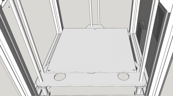
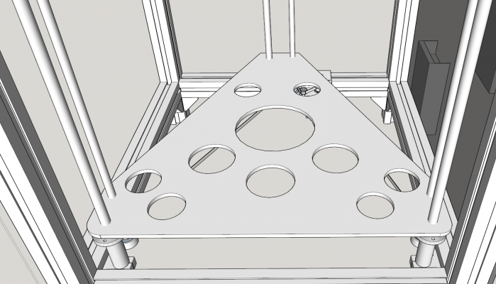
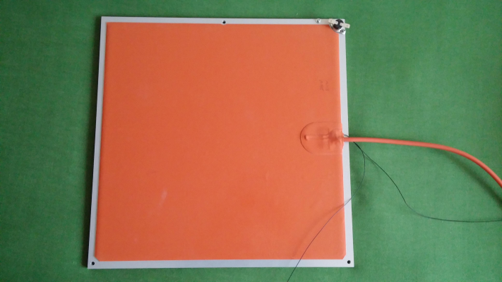
Now the heated bed... I plan on using an aluminium base + an adjustable aluminium heatspreader on top of it (maybe 6mm thick for both, not sure what is strong enough yet). First of all, I am wondering if the bed will be sturdy enough when mounted with just three screws (which simplifies alignment a lot).
(the holes will be tapered, I just didn't bother to draw that yet)
The second thing that I'm not too sure about is whether I should lighten the base by cutting out some parts of it, or just keep it as a whole? In addition to lowering the weight, the cutouts should also reduce stress/deformation caused by thermal expansion, although that will be minimal. Again, I am wondering if that will be strong enough or not... (as of now, the cutouts are pretty much random. Any tips on how to do them "properly"? )
And the last thing I am worried about is the placement of the middle screw+guide on the Z axis. As it is now, even if the combo is in the center, the screw is offset to one side and the guide is to the other. I wonder if the loss of symmetry will cause any binding or other problems?
EDIT Going along with wiring, I figured I need to start thinking about how to keep them out of the way. A drag chain seems like a good option, and I might be able to print one when I'm finished... So, another question - if I'll use a drag chain turned on its side for all the X carriage wires, should I put the bowden tube in it too? That would be a pretty small bending radius (especially at the ends) and I'm unsure if that would be a bit too much. Plus, I would need to design some anchor point for the chain...
And if I leave the tube alone, I might as well bundle all the cables with it in any other type of cable sleeving...
Edited 3 time(s). Last edit at 01/09/2016 10:16AM by Dalius98.
|
Re: My 350x350mm CoreXY design January 16, 2016 12:34PM |
Registered: 8 years ago Posts: 67 |
Alright, nevermind, I'll figure out the above myself. 
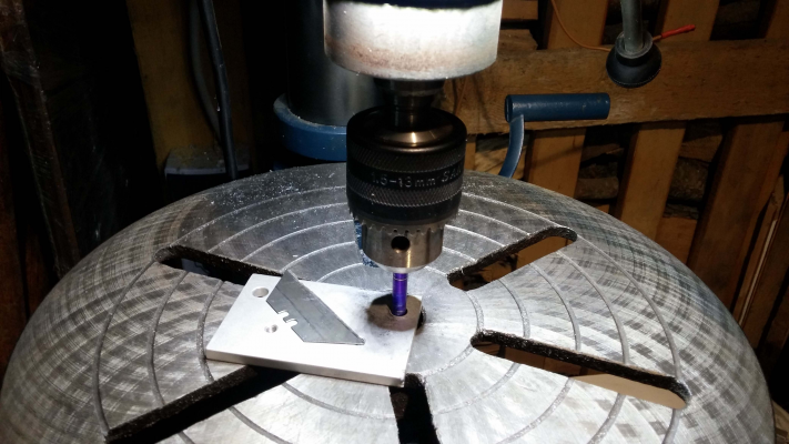
Just had some free time, so I put my design to the test. I was mostly concerned if the 2mm from a mounting hole to the edge of mounting plate will be enough, and it seems to work OK... Oh, and here's my fancy miter saw to cut aluminum
I'm really itching to cut some aluminum and put something together, so just some final considerations before I finalize the dimensions...
When building a heated enclosure, is it better to leave the motors outside, with a hole for the belts to pass through, or to put them inside to get a more airtight enclosure? Won't they get too hot?

Just had some free time, so I put my design to the test. I was mostly concerned if the 2mm from a mounting hole to the edge of mounting plate will be enough, and it seems to work OK... Oh, and here's my fancy miter saw to cut aluminum

I'm really itching to cut some aluminum and put something together, so just some final considerations before I finalize the dimensions...
When building a heated enclosure, is it better to leave the motors outside, with a hole for the belts to pass through, or to put them inside to get a more airtight enclosure? Won't they get too hot?
|
Re: My 350x350mm CoreXY design January 16, 2016 10:18PM |
Registered: 11 years ago Posts: 5,780 |
Many of the wires in my machine are >2m long. No problems at all if you use adequate gauge wire. I think I used 20 ga wire for the motors, heavier stuff for the extruder heater, and much heavier stuff for the bed heater. Thermistor and end stop wires don't have to be anything special. I did twist the motor wires (one twisted pair per coil) and heater wires using an electric drill and a vise. Twisting helps prevent inducing currents in wires that are in close proximity to higher current wires.
Ultra MegaMax Dominator 3D printer: [drmrehorst.blogspot.com]
Ultra MegaMax Dominator 3D printer: [drmrehorst.blogspot.com]
|
Re: My 350x350mm CoreXY design January 19, 2016 05:28PM |
Registered: 8 years ago Posts: 67 |
Well, I'm finally done with my last exam this semester - will be able to concentrate on the build a lot more. I've spent this day pretty productively - finished the aluminum mounting plates, experimented on making plastic leadscrew nuts, and started assembling the frame.
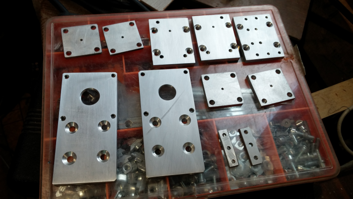
There's not much to talk about the mounting plates, other than they look sexy - I love the look of aluminum
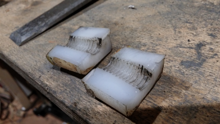
The nuts are a bit of a more interesting story: I bought regular steel nuts with my leadscrews, figuring I'll print some plastic ones as soon as I'm able to (yeah, steel-on-steel is not a good idea, I know). But I found this big chunk of PTFE/HDPE/some sort of Acetal in the trash (I really have no idea what it is) and just thought I'll try my luck, see if it has a low enough melting temperature to do me any good. I remember reading about this technique in some forum. This was a fourth try, and it came out pretty good - the threads were in a good shape, except for a small part I broke when trying to unscrew it (and the parts I mangled trying to break it apart) - the fit is incredibly tight, and I will need to experiment a bit more to figure out a good way to make it a bit looser. And the two halves joined so good, that I couldn't even split the nut again in the same place.
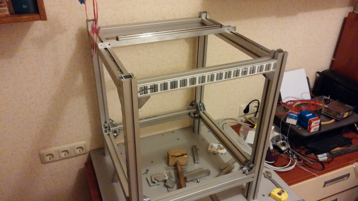
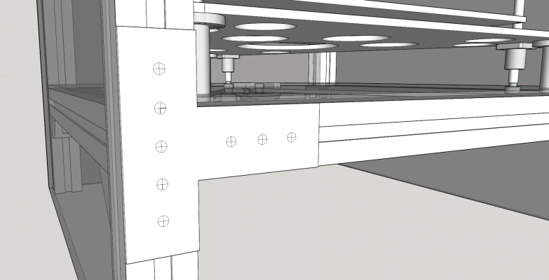
The last thing I did was I started to assemble the frame - mostly just to see if there's any obvious things that I've missed. Then I had the idea of making some aluminum plates to join the extrusions together... The angle brackets I have on hand aren't made for this type of extrusion, and the "fins" that protrude from the brackets are a bit too loose to fit in the slots of the extrusion properly, thus allowing the extrusions to be mounted crooked and whatnot. The plates would register against the faces of the extrusion, and hopefully help with the alignment, maybe even be strong enough to replace those crappy angle brackets...
EDIT #1: just realized I should make them a proper triangle insted of a "T" if I plan to use them to replace the angle brackets, but that will use up even more of my aluminum leftovers
EDIT #2 Another idea - Since the nuts on Z axis are "kind of" stationary (well, they are fixed to the Z platform, and not turning), it doesn't really matter if the threads are a bit off-center, as long as I can mount them properly, right? That stuff is pretty hard to machine with my current equipment (meaning it doesn't sand well ) and that might simplify things a bit... although there are already made concentric ones on ebay for pretty cheap, and even some with a nice 3D printed flange, but more expensive... Any comments?
That's good to hear, I think my shielded 21awg cables will do nicely.
Edited 2 time(s). Last edit at 01/19/2016 05:51PM by Dalius98.
There's not much to talk about the mounting plates, other than they look sexy - I love the look of aluminum

The nuts are a bit of a more interesting story: I bought regular steel nuts with my leadscrews, figuring I'll print some plastic ones as soon as I'm able to (yeah, steel-on-steel is not a good idea, I know). But I found this big chunk of PTFE/HDPE/some sort of Acetal in the trash (I really have no idea what it is) and just thought I'll try my luck, see if it has a low enough melting temperature to do me any good. I remember reading about this technique in some forum. This was a fourth try, and it came out pretty good - the threads were in a good shape, except for a small part I broke when trying to unscrew it (and the parts I mangled trying to break it apart) - the fit is incredibly tight, and I will need to experiment a bit more to figure out a good way to make it a bit looser. And the two halves joined so good, that I couldn't even split the nut again in the same place.
The last thing I did was I started to assemble the frame - mostly just to see if there's any obvious things that I've missed. Then I had the idea of making some aluminum plates to join the extrusions together... The angle brackets I have on hand aren't made for this type of extrusion, and the "fins" that protrude from the brackets are a bit too loose to fit in the slots of the extrusion properly, thus allowing the extrusions to be mounted crooked and whatnot. The plates would register against the faces of the extrusion, and hopefully help with the alignment, maybe even be strong enough to replace those crappy angle brackets...
EDIT #1: just realized I should make them a proper triangle insted of a "T" if I plan to use them to replace the angle brackets, but that will use up even more of my aluminum leftovers

EDIT #2 Another idea - Since the nuts on Z axis are "kind of" stationary (well, they are fixed to the Z platform, and not turning), it doesn't really matter if the threads are a bit off-center, as long as I can mount them properly, right? That stuff is pretty hard to machine with my current equipment (meaning it doesn't sand well
 ) and that might simplify things a bit... although there are already made concentric ones on ebay for pretty cheap, and even some with a nice 3D printed flange, but more expensive... Any comments?
Quote
the_digital_dentist
Many of the wires in my machine are >2m long. No problems at all if you use adequate gauge wire. I think I used 20 ga wire for the motors, heavier stuff for the extruder heater, and much heavier stuff for the bed heater. Thermistor and end stop wires don't have to be anything special. I did twist the motor wires (one twisted pair per coil) and heater wires using an electric drill and a vise. Twisting helps prevent inducing currents in wires that are in close proximity to higher current wires.
That's good to hear, I think my shielded 21awg cables will do nicely.
Edited 2 time(s). Last edit at 01/19/2016 05:51PM by Dalius98.
|
Re: My 350x350mm CoreXY design January 29, 2016 01:39PM |
Registered: 8 years ago Posts: 67 |
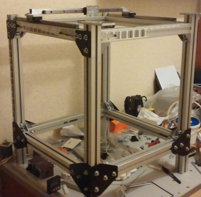
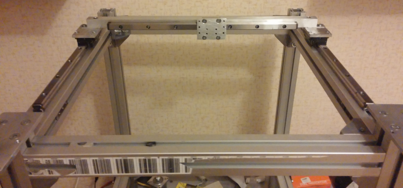
Finally got something done on the printer - finished and mounted all those homemade brackets, squared up the frame as much as I could, and then mounted the linear guides. Managed to adjust them parallel across the length with just 0.02-0.03mm deviation between the ends (SKF recommends 0.018), unfortunately, adjusting the height deviation was a bit harder - while both ends are on the same level, there's almost 0.15mm deviation in the middle of the rails (although, I get 0.17 as a recommendation across 500mm length - I'm not sure if the math is right - can it be that much?). I might try and see if there's some debris under the rails, but I don't really want to spend another two hours aligning them 
My carriages have a minimal amount of preload, but they stay in place when subjected against gravity - the linear bearings on rods do not. I think I like it better this way. Carriages move smoothly, but they are pretty loud, more than I expected at least... It's mostly because the sound resonates through the aluminium tubes/frame - maybe I should put some kind of insulating material between them, like packing foam? or would that reduce stability / provide no benefit when tightened down?
Got some stuff in the mail today. A few spare pulleys and some SSRs. Pulleys took 12 full weeks to arrive - I managed to choose the worst time to order things I guess. didn't realize Christmas rush starts in November And the SSRs... they're huge... Anyway, I'm quite happy at the moment, just need to make some spacers, cut some screws to length, and I can route the belts for XY motion. Z will have to wait, since I have no bearings to hold the screws...

My carriages have a minimal amount of preload, but they stay in place when subjected against gravity - the linear bearings on rods do not. I think I like it better this way. Carriages move smoothly, but they are pretty loud, more than I expected at least... It's mostly because the sound resonates through the aluminium tubes/frame - maybe I should put some kind of insulating material between them, like packing foam? or would that reduce stability / provide no benefit when tightened down?
Got some stuff in the mail today. A few spare pulleys and some SSRs. Pulleys took 12 full weeks to arrive - I managed to choose the worst time to order things I guess. didn't realize Christmas rush starts in November
 And the SSRs... they're huge... Anyway, I'm quite happy at the moment, just need to make some spacers, cut some screws to length, and I can route the belts for XY motion. Z will have to wait, since I have no bearings to hold the screws...
|
Re: My 350x350mm CoreXY design January 30, 2016 01:44PM |
Registered: 8 years ago Posts: 67 |
Heh, I just couldn't stop myself from checking out if this thing works. Even though the small flanged bearings (for homemade toothed idlers) didn't arrive yet, I just made something up from some washers - there's more friction than there will be in the future, but it works for a test. Didn't spend much time configuring yet, just added CoreXY settings and fired up Pronterface. A few simple X and Y movements were enough to satisfy my curiosity.
[Video link]
Sorry for the shaky camera, had one hand on the computer while the other was filming
Keen eyed viewers might notice that my motors are different, and the belts are rubbing on something, but that's because I used whatever stuff I had laying around - I don't have other motors wired up yet, and no toothed idlers that would fix the rubbing problem...
[Video link]
Sorry for the shaky camera, had one hand on the computer while the other was filming

Keen eyed viewers might notice that my motors are different, and the belts are rubbing on something, but that's because I used whatever stuff I had laying around - I don't have other motors wired up yet, and no toothed idlers that would fix the rubbing problem...
|
Re: My 350x350mm CoreXY design January 30, 2016 02:11PM |
Registered: 11 years ago Posts: 5,780 |
Wow! I thought my printer was noisy! Was microstepping turned on?
It looks like a good, solid build. I'm sure it will produce quality prints when you're done.
Ultra MegaMax Dominator 3D printer: [drmrehorst.blogspot.com]
It looks like a good, solid build. I'm sure it will produce quality prints when you're done.
Ultra MegaMax Dominator 3D printer: [drmrehorst.blogspot.com]
|
Re: My 350x350mm CoreXY design January 30, 2016 03:12PM |
Registered: 8 years ago Posts: 67 |
I'm not sure, to be honest. Didn't have time to really dig in to the config, I'm not even sure if microstepping is something I can adjust on Smoothieboard.Quote
the_digital_dentist
Wow! I thought my printer was noisy! Was microstepping turned on?
It looks like a good, solid build. I'm sure it will produce quality prints when you're done.
But yeah, all the little sounds get amplified by the frame, I'll see if I can do anything about it in the future.
|
Re: My 350x350mm CoreXY design January 30, 2016 08:03PM |
Registered: 11 years ago Posts: 5,780 |
Microstepping is fixed at 16:1 on smoothieboard. Maybe the acceleration and/or motor currents were set a little too high...
Ultra MegaMax Dominator 3D printer: [drmrehorst.blogspot.com]
Ultra MegaMax Dominator 3D printer: [drmrehorst.blogspot.com]
|
Re: My 350x350mm CoreXY design February 19, 2016 07:27AM |
Registered: 8 years ago Posts: 67 |
So, after a few weeks of not doing anything on this project, I've decided it's time to quit stalling.
Spent the last evening disassembling and reassembling the frame, hopefully I'll be able to align the linear rails better this time.
Anyway, I have a question I would like to ask:
What would be the best way to align the Z axis rods square to the other axis (and parallel to themselves)? I guess I could make the three of them parallel by measuring the distance between each pair on top and bottom, but that's a bit complicated when the distance between the rails is >400mm - can't really measure that with a caliper, and getting readings off a tape measure is rather hard too... This should work on aligning the leadscrews to the rails though. And I can't think of a way to make sure if the rails are square to the XY plane - I guess that would be apparent on a printed object (shifted layers and whatnot). I do have a digital protractor/angle box - but I don't trust that thing too much - if there is another way, I would like to hear it.
Edited 1 time(s). Last edit at 02/19/2016 07:28AM by Dalius98.
|
Re: My 350x350mm CoreXY design February 19, 2016 11:06AM |
Registered: 11 years ago Posts: 5,780 |
I would probably space the two Y axis linear guides (and Z axis rails or guide) by putting a spacer (wood or metal rod cut to exact size) between them.
When I set up my printer, I did the initial setup using one of these:
[www.ebay.com]
You place this device against the guide rails/linear guides, not the frame pieces they are bolted to.
Then I printed a part and measured diagonals to check squareness and made adjustments as required.
[www.youmagine.com]
Ultra MegaMax Dominator 3D printer: [drmrehorst.blogspot.com]
|
Re: My 350x350mm CoreXY design February 19, 2016 12:22PM |
Registered: 8 years ago Posts: 67 |
Quote
the_digital_dentist
I would probably space the two Y axis linear guides (and Z axis rails or guide) by putting a spacer (wood or metal rod cut to exact size) between them.
Thanks for the idea - I did the initial setup by using spacers placed between the frame sides and the rod holders, and didn't realize I could just as easily use a spacer between the rods

as for the two Y axis rails, they were a bit more straightforward to setup - I used a dial indicator coupled to one of the carriages via an aluminum tube. That would be a lot harder to do on round rods.
Quote
the_digital_dentist
When I set up my printer, I did the initial setup using one of these:
[www.ebay.com]
You place this device against the guide rails/linear guides, not the frame pieces they are bolted to.
Then I printed a part and measured diagonals to check squareness and made adjustments as required.
[www.youmagine.com]
Right, mine was something like 20$, that's why I don't trust it too much. But if I can measure the out-of-squariness by making test prints, I guess I should just concentrate on getting the rails parallel.
|
Re: My 350x350mm CoreXY design February 19, 2016 02:30PM |
Registered: 11 years ago Posts: 1,049 |
DD
Is your coreXY design available somewhere?
Son of MegaMax is NOT CoreXY.
It looks like on SoM, that more than half of the build bed has to stick out the back end
to print of the front of the bed.
Sorry is there a SoM Topic someplace?

Is your coreXY design available somewhere?
Son of MegaMax is NOT CoreXY.
It looks like on SoM, that more than half of the build bed has to stick out the back end
to print of the front of the bed.
Sorry is there a SoM Topic someplace?

Quote
the_digital_dentist
Are you intending to print ABS? If so you might want to start thinking about how you're going to enclose the machine to keep the build chamber warm. On the same subject, have you considered what happens to all those structures when the temperature rises? The aluminum will expand more than the steel guide rails. That will create bending forces that may cause the guide mechanisms to bind.
I've been working on a similar CoreXY design and trying to figure out how to deal with the differential thermal expansion. I'm starting to think that the rectangular frame that holds the linear guides should be made of steel. A steel frame for at least that part of the printer would eliminate the problems created by thermal expansion. That steel frame can then be mounted in an easy to build aluminum frame, with the mount designed to allow the aluminum frame to expand more than the steel without creating any stresses on either.
|
Re: My 350x350mm CoreXY design February 19, 2016 11:35PM |
Registered: 11 years ago Posts: 5,780 |
My CoreXY hasn't started construction yet. Still gathering parts and exploring some options.
SoM can be seen in detail by clicking the link in my sig, below.
You're right, SoM is not CoreXY. The bed is confined entirely within the printer. The Y axis motor sticks out the back because it runs hot and I didn't want it inside the build chamber.
Ultra MegaMax Dominator 3D printer: [drmrehorst.blogspot.com]
|
Re: My 350x350mm CoreXY design November 01, 2016 08:14PM |
Registered: 8 years ago Posts: 67 |
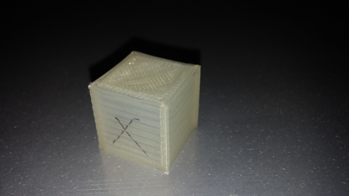
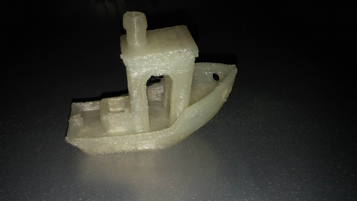
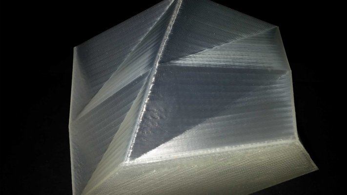
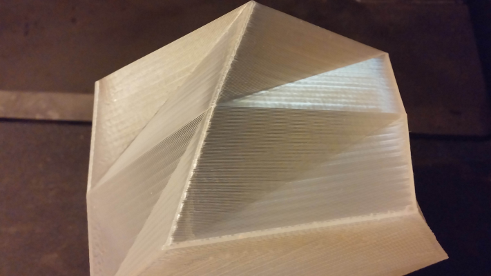
I printed an actual thing (for the first time) today - time to update this thread... I've re-started working on the printer back in September, took me a while to get to this stage - but it's still far from being finished. Anyway, I'd thought I will post some pictures, ask some questions, someone will help me out with the calibration, right?
So, could anyone share some good calibration/troubleshooting guides?
As far as my test prints go, it seems like I have some temperature related issues, and a little bit of Z banding...
Another uneducated guess would be that I need to tweak jerk/acceleration values, because the corners of the cube bulge out a bit and there's some artifact visible on the vase... But what I really need is either a good guide or some more opinions.
I haven't done any actual calibration yet - I am using a suggested steps/mm value for Titan extruder (and the XYZaxis), default speeds/settings in Slic3r . I'm still missing a print cooling fan and a Z endstop... and don't get me started on the wiring...
Now I know it's hard to see anything on a part made from white filament, but that's just something I had even before starting the 3D printer build (so a really sub-optimal solution: no recommended temperatures, and probably some absorbed moisture), I'll try to improve this aspect first.
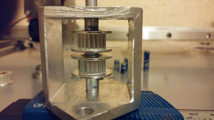
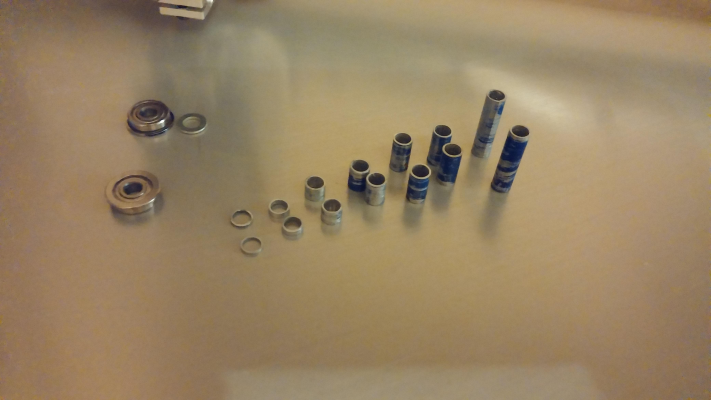
For anyone interested in the build process, I have some pictures too. It was an interesting task to cut aluminum spacers for the pulleys, but it all worked out in the end, and with decent accuracy. I've used 5mm aluminum shafts which I've threaded on the ends, and 6mm OD pipe as spacers.
I have left myself an option of upgrading to 9mm belts without many changes.
One other question I have, is how do I check that the pulleys/idlers are at a perfect 90deg to the belts, and not contacting them on an angle? I have a way to adjust that, but first I need to know what and how much...
And one more thing: has anyone ever heard of XPpower? I have a few 15A power supplies made by them (JPS350PS24), and I'm not sure if that would be an improvement over my generic Chinese 10A one... Their website looks nice, and the few models I find for sale cost quite a bit, but that's not really a suitable proof of quality, is it?
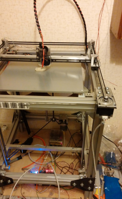
EDIT: oh, almost forgot the photo of the actual machine... The motor mounts are adjustable side to side to line up the belts properly, and I can tension them by sliding the motor in and out, although it seems I can tension them enough at the carriage side... Think I'm going to remake the mounts to something with more "meat" left on them...
EDIT2: uploaded a short video showcasing basically nothing (the very first try printing). I just don't have anything more suitable yet.
Edited 2 time(s). Last edit at 11/01/2016 08:41PM by Dalius98.
So, could anyone share some good calibration/troubleshooting guides?
As far as my test prints go, it seems like I have some temperature related issues, and a little bit of Z banding...
Another uneducated guess would be that I need to tweak jerk/acceleration values, because the corners of the cube bulge out a bit and there's some artifact visible on the vase... But what I really need is either a good guide or some more opinions.
I haven't done any actual calibration yet - I am using a suggested steps/mm value for Titan extruder (and the XYZaxis), default speeds/settings in Slic3r . I'm still missing a print cooling fan and a Z endstop... and don't get me started on the wiring...

Now I know it's hard to see anything on a part made from white filament, but that's just something I had even before starting the 3D printer build (so a really sub-optimal solution: no recommended temperatures, and probably some absorbed moisture), I'll try to improve this aspect first.
For anyone interested in the build process, I have some pictures too. It was an interesting task to cut aluminum spacers for the pulleys, but it all worked out in the end, and with decent accuracy. I've used 5mm aluminum shafts which I've threaded on the ends, and 6mm OD pipe as spacers.
I have left myself an option of upgrading to 9mm belts without many changes.
One other question I have, is how do I check that the pulleys/idlers are at a perfect 90deg to the belts, and not contacting them on an angle? I have a way to adjust that, but first I need to know what and how much...
And one more thing: has anyone ever heard of XPpower? I have a few 15A power supplies made by them (JPS350PS24), and I'm not sure if that would be an improvement over my generic Chinese 10A one... Their website looks nice, and the few models I find for sale cost quite a bit, but that's not really a suitable proof of quality, is it?
EDIT: oh, almost forgot the photo of the actual machine... The motor mounts are adjustable side to side to line up the belts properly, and I can tension them by sliding the motor in and out, although it seems I can tension them enough at the carriage side... Think I'm going to remake the mounts to something with more "meat" left on them...
EDIT2: uploaded a short video showcasing basically nothing (the very first try printing). I just don't have anything more suitable yet.
Edited 2 time(s). Last edit at 11/01/2016 08:41PM by Dalius98.
|
Re: My 350x350mm CoreXY design November 02, 2016 08:26AM |
Registered: 11 years ago Posts: 5,780 |
It looks pretty solid, just have to get the Z axis sorted out... Some of the print quality problems will disappear when you get the extruder calibrated. It looks like you're over extruding a bit.
What sort of controller are you using?
I just bought a MeanWell LRS-200-24 supply for a CubeX printer that I am rehabilitating. $24 new/shipped via ebay. This isn't one of their industrial supplies, but it has no fan, so it's quiet, and has all sorts of protection circuits built in to prevent failures due to "oops". I bought a 750W 24V supply for my other printer for $50 via ebay (used) and it is one of MW's industrial models, so it has a pretty loud fan that runs all the time. My past experience with cheapo "LED" supplies sold on ebay is that if the fan ever turns on the thing isn't going to last very long. Those supplies have very ineffective (or no) protection circuits.
Ultra MegaMax Dominator 3D printer: [drmrehorst.blogspot.com]
|
Re: My 350x350mm CoreXY design November 02, 2016 01:45PM |
Registered: 8 years ago Posts: 67 |
I got myself the new Duet Wifi after I fried my Smoothieboard (stupid mistake I made, put me off from this project for a while)...
As for the Z axis, I have figured out the endstop switch mounting, just have to implement it. For now I'm manually setting Z height before each print, but it's a bit fiddly to say the least.
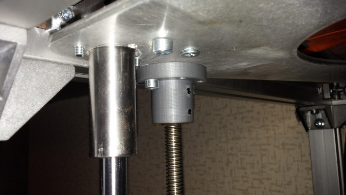
One of the things I'll change whenever I have the chance, is upgrade these housings for trapezoidal nuts. These are PLA housings that hold a round delrin nut inside - but they flex and bind the screws depending on how hard (and if equal on the other side) the housing is tightened to the bed platform. Will upgrade to aluminium when I convince my friend to turn them for me.
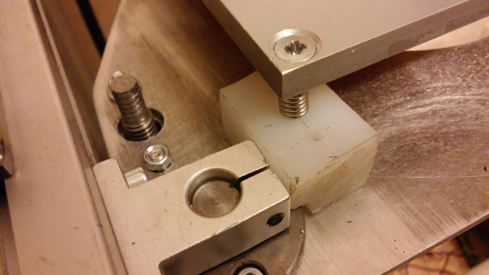
I'm using these plastic blocks (teflon perhaps?) to hold the bed leveling screws. I bet these seem familiar to You - that was a really good idea

Sorry, only registered users may post in this forum.
