New printer build! My CoreXY.
Posted by robkar
|
New printer build! My CoreXY. January 24, 2016 04:00PM |
Registered: 8 years ago Posts: 24 |
Hi!
I am in the process of building a CoreXY printer and thought I might get some feedback here! I have previously designed and built a delta printer ( LINK) which prints really well. However, I now need (want) a bigger build volume. I started to investigate what it would take to enlarge the delta, but in order to achieve at least a 300x300mm build size the machine will be pretty tall. That, in addition to the fact that it is more fun to try something new, has made me going for a CoreXY variant.
My targets for the printer were/are:
What I have decided so far is:
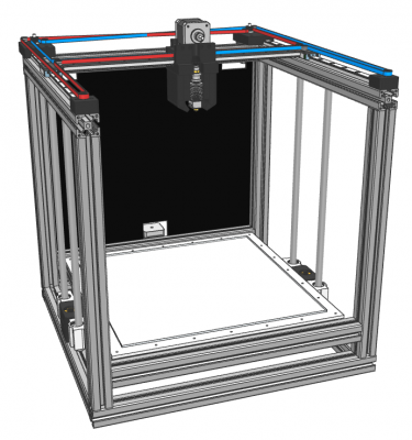
I am pretty satisfied with the X-Y design as of now, but I am struggling on the Z axis. My two main alternatives are:
See the two images of the alternatives. None of them are finished designs, especially not the rail one, but I think you’ll get the idea.
So, any suggestions for my Z setup? Which one should I go for?
I have read most of the threads here regarding different CoreXY concepts so I know people have designed similar printers (Dalius98, filipeCampos, bonmotwang, patrickrio, digital dentist, LarsK and more!), I appreciate the inspiration! I will soon update this thread with more pictures and elaborate more on the other aspects of the design (Core XY setup, frame, effector, etc.).
Peace!
Edited 2 time(s). Last edit at 01/25/2016 05:02PM by robkar.
I am in the process of building a CoreXY printer and thought I might get some feedback here! I have previously designed and built a delta printer ( LINK) which prints really well. However, I now need (want) a bigger build volume. I started to investigate what it would take to enlarge the delta, but in order to achieve at least a 300x300mm build size the machine will be pretty tall. That, in addition to the fact that it is more fun to try something new, has made me going for a CoreXY variant.
My targets for the printer were/are:
- < 500x500x500 mm frame size
- > 300x300x300 mm build volume
- CoreXY kinematics
- Being rather fast (an extremely tangible, measurable target, I know)
- Not look like a disaster
What I have decided so far is:
- 3030 aluminum extrusions for frame
- Linear rails for X-Y motion
- Bowden extruder
I am pretty satisfied with the X-Y design as of now, but I am struggling on the Z axis. My two main alternatives are:
- Four linear rods with two lead screws belt driven by one stepper. I know that three points defines a plane etc., but in reality (with printed plastic parts) I doubt that everything will be stiff enough to not allow for any misalignment at all. Am I wrong?
- Using two more MGN12 linear rails and put them on each side of the bed, accompanied by two lead screws. They would be placed in the middle of the bed, so it is not cantilevered. I have only positive experience of the linear guides from my delta project, so why not use them here as well? And if buying from China two linear guides are actually not THAT much more expensive than four rods + four bearings.
See the two images of the alternatives. None of them are finished designs, especially not the rail one, but I think you’ll get the idea.


So, any suggestions for my Z setup? Which one should I go for?
I have read most of the threads here regarding different CoreXY concepts so I know people have designed similar printers (Dalius98, filipeCampos, bonmotwang, patrickrio, digital dentist, LarsK and more!), I appreciate the inspiration! I will soon update this thread with more pictures and elaborate more on the other aspects of the design (Core XY setup, frame, effector, etc.).
Peace!
Edited 2 time(s). Last edit at 01/25/2016 05:02PM by robkar.
|
Re: New printer build! My CoreXY. January 24, 2016 05:08PM |
Registered: 8 years ago Posts: 67 |
Thanks for the shoutout, haha 
Anyway, I would like to express the concerns I'm having about your frame design - yes, it looks nice with two unsupported corners, and getting big parts off the build plate would be easier, but aren't you sacrificing stability for pretty much nothing? I mean, even if the extrusions are strong enough not to sag or flex in any way (which I'm pretty sure they are), there's something that just feels wrong when looking at it. Just my opinion.
As for the rails vs rods debate, I can tell just one thing - the different amount of play in the bearings between the two is NOT big enough to feel by hand. I have some good quality SKF rails for my XY motion, and then I have some (decent, I guess) 12mm smooth rods from Germany, with Chinese LMF12LUU bearings for them. I haven't done any type of "real" measurements or comparison between the two, although I have a dial indicator and could jig something up if that's what you're interested in. I still suspect that even Chinese rails should offer better quality than rods, and sometimes I wonder if I should have gone for them instead. The deciding factor for me was import costs on Chinese rails, so I went with local sources...
You probably meant that it's three points that define a plane (well, at least that is the correct answer), and I can understand the doubts you're having - I am concerned about my design as well. I would be glad to comment anything about the three screw solution, but unfortunately I am not that far in the build process. And it seems that the pillow block bearings I've ordered for the screws might have disappeared during shipment, so it will probably take a while until I get to that stage...Quote
robkar
Four linear rods with two lead screws belt driven by one stepper. I know that four points defines a plane etc., but in reality (with printed plastic parts) I doubt that everything will be stiff enough to not allow for any misalignment at all. Am I wrong?
Anyway, I would like to express the concerns I'm having about your frame design - yes, it looks nice with two unsupported corners, and getting big parts off the build plate would be easier, but aren't you sacrificing stability for pretty much nothing? I mean, even if the extrusions are strong enough not to sag or flex in any way (which I'm pretty sure they are), there's something that just feels wrong when looking at it. Just my opinion.
As for the rails vs rods debate, I can tell just one thing - the different amount of play in the bearings between the two is NOT big enough to feel by hand. I have some good quality SKF rails for my XY motion, and then I have some (decent, I guess) 12mm smooth rods from Germany, with Chinese LMF12LUU bearings for them. I haven't done any type of "real" measurements or comparison between the two, although I have a dial indicator and could jig something up if that's what you're interested in. I still suspect that even Chinese rails should offer better quality than rods, and sometimes I wonder if I should have gone for them instead. The deciding factor for me was import costs on Chinese rails, so I went with local sources...
|
Re: New printer build! My CoreXY. January 24, 2016 05:37PM |
Registered: 8 years ago Posts: 346 |
very cool design...
i have the same opinion was dalius98 about the frame, looks very cool but i not sure if you will have some stability problem. But if your atual design was problem then you could add a 3 vertical bar behind to add ridigity and put on it an third rail for the z axis. i sugest to replace bowden to a direct setup, it will give less possible problem and better print quality.
i have the same opinion was dalius98 about the frame, looks very cool but i not sure if you will have some stability problem. But if your atual design was problem then you could add a 3 vertical bar behind to add ridigity and put on it an third rail for the z axis. i sugest to replace bowden to a direct setup, it will give less possible problem and better print quality.
|
Re: New printer build! My CoreXY. January 24, 2016 06:53PM |
Registered: 11 years ago Posts: 5,780 |
I think your frame may be stiff enough as is, but if there were vertical members at all four corners it might be easier to enclose the machine using simple flat panels attached to the sides. It certainly won't cost much to add two more extrusion pieces to the frame.
Don't forget to plan places for the electronics, wiring, and the filament spool(s) or yours will end up like many other designs- very cool looking in your CAD models because you left that stuff out, but when you actually build it, the controller board ends up in some weird place because it was an afterthought.
I say go with linear guides. They are much more compact and ultimately lighter weight than pairs of round rails and bearings. You don't have to worry about flex or keeping them parallel, either, and there is zero play in the bearing blocks. If you are going to enclose the machine to print ABS, you do have to worry about the thermal expansion of the aluminum frame vs the much smaller expansion of the steel guide rails which is primarily a concern for the XY mechanism. I am still deciding what to do about that in the design I am working on.
Ultra MegaMax Dominator 3D printer: [drmrehorst.blogspot.com]
|
Re: New printer build! My CoreXY. January 25, 2016 05:01PM |
Registered: 8 years ago Posts: 24 |
Quote
Dalius98
You probably meant that it's three points that define a plane (well, at least that is the correct answer), and I can understand the doubts you're having - I am concerned about my design as well. I would be glad to comment anything about the three screw solution, but unfortunately I am not that far in the build process. And it seems that the pillow block bearings I've ordered for the screws might have disappeared during shipment, so it will probably take a while until I get to that stage...
Haha good start I got there! I know it is 3 points. Might edit my post, first impressions you know..
 I will probably just use two lead screws, the question I have is whether four linear rods would cause problems or not. Probably not.
Quote
Dalius98
Anyway, I would like to express the concerns I'm having about your frame design - yes, it looks nice with two unsupported corners, and getting big parts off the build plate would be easier, but aren't you sacrificing stability for pretty much nothing? I mean, even if the extrusions are strong enough not to sag or flex in any way (which I'm pretty sure they are), there's something that just feels wrong when looking at it. Just my opinion.
I'm actually not concerned about this, I am pretty sure the 3030 extrusions won't sag on that unsupported distance. With metal brackets the protrusion is only like 160mm. I will start like this, but if I am wrong it is really simple to just move the middle extrusions to the corners. For me this design just feels so right

Quote
filipeCampos
very cool design...
i have the same opinion was dalius98 about the frame, looks very cool but i not sure if you will have some stability problem. But if your atual design was problem then you could add a 3 vertical bar behind to add ridigity and put on it an third rail for the z axis. i sugest to replace bowden to a direct setup, it will give less possible problem and better print quality.
I have used a bowden setup for my delta, which has A LOT of printing hours, and have very few issues. Sure, you need to carefully calibrate your retractions settings, but the low weight of the Bowden setup is very beneficial. I like to print fast, and moving a heavy stepper around with high acceleration settings results in high forces. It is a trade-off! If going for a direct drive I would look into designing something around a geared Nema08 or Nema11, that might be interesting. Do you feel your build is limited by a heavy carrage, or what is your limiting factor when it comes to printing fast?
Quote
the_digital_dentist
I think your frame may be stiff enough as is, but if there were vertical members at all four corners it might be easier to enclose the machine using simple flat panels attached to the sides. It certainly won't cost much to add two more extrusion pieces to the frame.
Don't forget to plan places for the electronics, wiring, and the filament spool(s) or yours will end up like many other designs- very cool looking in your CAD models because you left that stuff out, but when you actually build it, the controller board ends up in some weird place because it was an afterthought.
I say go with linear guides. They are much more compact and ultimately lighter weight than pairs of round rails and bearings. You don't have to worry about flex or keeping them parallel, either, and there is zero play in the bearing blocks. If you are going to enclose the machine to print ABS, you do have to worry about the thermal expansion of the aluminum frame vs the much smaller expansion of the steel guide rails which is primarily a concern for the XY mechanism. I am still deciding what to do about that in the design I am working on.
Nah, I moved the extrusions out of the front corners just because I wanted something slightly different from all the cubes out there
I might come back in a month and let you guys tell me I told you so! Regarding enclosing it I don't plan to do that, but as you say, if I change my mind it should be an easy fix.Agree on the electronics + wiring part! Need to plan ahead for that. In my delta build I designed brackets etc. with holes for wires, and the extra effort really gives it a neat look. My design is not finished at all, so these things are a good thing to keep in mind, thanks.
See the pictures below, I think this is my best shot at a Z axis design at the moment. I went with linear rails there as well, but placed them on the backside of the middle extrusions. They are now pretty much hidden there as I probably will put sheets of acrylic on the back half of the printer’s sides. I did a quick non-scientific test in which direction the rail blocks are more rigid, and while I couldn’t really determine that by rotating them by hand, this setup feels good in terms of reducing play.


Edited 1 time(s). Last edit at 01/25/2016 05:10PM by robkar.
|
Re: New printer build! My CoreXY. January 25, 2016 05:49PM |
Registered: 8 years ago Posts: 24 |
Another thing I am not completely sure on is the heated bed setup. I think I'll use aluminum extrusions as a frame to which I can bolt my Z axis carriages. My first idea was to use a custom made 5mm aluminum sheet on top, with a silicone heater glued to the bottom of it. Leveling would be done as usual, 4 screws with springs in each corner. I did a fast structural analysis of it, the deflection from the weight of itself is negligible:
Then I found this: HEATBED LINK
The outer dimensions are 328x328mm. My biggest possible print volume would be 340x340mm, so with a 330x330 mm glass sheet on top, I wouldn't loose much printable area. This bed is however just 2mm thick, which results in more deflection if only supported by spacers in the corners:
Has anyone used a +300x300mm bed of this kind? Is it really a problem? Would the custom made aluminum alternative be much better? It would be convenient to use as few custom made aluminum parts as possible, but if needed I'll do it.
Edited 3 time(s). Last edit at 01/25/2016 05:52PM by robkar.

Then I found this: HEATBED LINK
The outer dimensions are 328x328mm. My biggest possible print volume would be 340x340mm, so with a 330x330 mm glass sheet on top, I wouldn't loose much printable area. This bed is however just 2mm thick, which results in more deflection if only supported by spacers in the corners:

Has anyone used a +300x300mm bed of this kind? Is it really a problem? Would the custom made aluminum alternative be much better? It would be convenient to use as few custom made aluminum parts as possible, but if needed I'll do it.
Edited 3 time(s). Last edit at 01/25/2016 05:52PM by robkar.
|
Re: New printer build! My CoreXY. January 25, 2016 07:35PM |
Registered: 8 years ago Posts: 346 |
about the bowden extruder, i have used one at first and spend several weeks to try to get to work without retrations problems, the bowden ptfe tube was 50cm. at the end i was using retration value that reduced the problem but never complety solved. Changed to an direct one and never have any retration problem.
somes get good result with bowden, but not in my case. And to be honest i do not see how they do it...
about speed print, corexy allow to print fast with an direct extruder with no problem. i simply do not see the point of using an bowden setup in an corexy printer when you can simply use an direct.
in my printer the limitation of the print speed was never the weight of one direct extruder. at first i was limited by the use on an ramps board. Then, after changed to an 32bit, the limitation was the hotend that was not able to melt fast enought. From the test i made at the time, 120mm/s was the fastest i could use without losing print quality, i have an e3d v6 little.
At last, i changed to dual mk8 direct extruders. with this one the weight is the limitation factor. to have perfect quality i can not print more than 60mm/s for the outside walls, 80 to the infill and it was necessary to reduce the aceleration too. print to fast and i get lots of artefacts on the walls.
Edited 1 time(s). Last edit at 01/25/2016 07:37PM by filipeCampos.
|
Re: New printer build! My CoreXY. January 25, 2016 09:11PM |
Registered: 11 years ago Posts: 5,780 |
Let's review some high-school level geometry... A line is defined by 2 points. Add a third point, and you specify a plane. What does adding a fourth point do? I'll tell you.
When you try to "level" a bed (a plane, or at least, it is supposed to be a plane) using four screws, turning one screw causes that corner to lift up or go down. The diagonally opposite corner wants to move in the opposite direction by pivoting on the two screws that are adjacent to the first one that you turned, but it can't because its screw holds it down and its spring holds it up. That means when you turn a screw you flex the bed plate. How can you level a plate by flexing it? So, while 3 screws define a plane, four defines a potato chip (technically, a saddle). Good luck printing on that. With sufficient playing around you may get it flat enough to print at the center of the bed, but you probably won't get it flat enough and level enough to print over the entire bed surface.
The usual solution is to put a glass plate on the thin, bent aluminum plate in hopes of flattening the surface. It is better to use a flat, rigid piece of aluminum on a leveling system that will allow it to remain flat. Cast aluminum tooling plate is flat enough and rigid enough to do the job.
Using three screws allows you to adjust the bed level without bending it. If you arrange them right, you can adjust just two screws and level the bed perfectly. What you do is put two screws along one edge of the bed and the third screw at the middle of the opposite edge. Use one of the first screws for the reference (it doesn't get adjusted when leveling the bed) and use the other screw at that edge of the bed to adjust the pitch of the bed in that axis. For example, if the two screws are on the the Y axis of the bed, the one that you adjust adjusts the pitch in the Y axis. After that is adjusted, you go to the screw on the opposite side of the bed and adjust the roll around the Y axis and it doesn't affect the pitch at all.
If you are going to heat the bed, you should know that heating typically causes the bed to bow upwards in the center. The main reason is that the leveling screws are fixed in the unheated undercarriage while the bed is heated and expands. That puts lateral pressure against the leveling screws which in turn cause the bed to flex. That is why you must level and zero the bed while it is at print temperature, not room temperature. You should also make sure the extruder is at print temperature before leveling and zeroing. The nozzle always has a little plastic oozing out and if you zero the bed at room temp the plastic is there and solid and will cause you to set the nozzle too high above the bed, resulting in poor print adhesion. Heating the nozzle to print temperature liquifies the plastic and allows you to set the zero point accurately.
Ultra MegaMax Dominator 3D printer: [drmrehorst.blogspot.com]
|
Re: New printer build! My CoreXY. January 27, 2016 03:07PM |
Registered: 8 years ago Posts: 24 |
Quote
filipeCampos
about the bowden extruder, i have used one at first and spend several weeks to try to get to work without retrations problems, the bowden ptfe tube was 50cm. at the end i was using retration value that reduced the problem but never complety solved. Changed to an direct one and never have any retration problem.
somes get good result with bowden, but not in my case. And to be honest i do not see how they do it...
about speed print, corexy allow to print fast with an direct extruder with no problem. i simply do not see the point of using an bowden setup in an corexy printer when you can simply use an direct.
in my printer the limitation of the print speed was never the weight of one direct extruder. at first i was limited by the use on an ramps board. Then, after changed to an 32bit, the limitation was the hotend that was not able to melt fast enought. From the test i made at the time, 120mm/s was the fastest i could use without losing print quality, i have an e3d v6 little.
At last, i changed to dual mk8 direct extruders. with this one the weight is the limitation factor. to have perfect quality i can not print more than 60mm/s for the outside walls, 80 to the infill and it was necessary to reduce the aceleration too. print to fast and i get lots of artefacts on the walls.
Yes, both systems have their pros and cons. I own one Printrbot Simple Metal (direct drive + moving gantry) and one delta (bowden). The Printrbot was more straightforward to set up and do print really well, at low speed. The moving mass is just to big for higher speeds, but it does not have the mechanical advantages of a coreXY, so there might very well be a difference there. The delta on the other hand can produce the same quality at double the speed, which I assume is due to the low weight of it.
However, with a rigid enough machine you can of course have a heavier direct extruder! I will start with a bowden, but might change my mind later on if the machine seem robust enough.
Interesting point regarding the 32bit board, I have not yet decided what route to go there.. I will probably by a duet 0.6 from replikeo, but my initial plan was to put that one in my delta, and move the ramps to my new CoreXY. I will read the other threads on the subject and make up my mind. Maybe I'll just buy two duets!
My Delta Printer: [www.thingiverse.com]
|
Re: New printer build! My CoreXY. January 27, 2016 03:21PM |
Registered: 8 years ago Posts: 24 |
Quote
the_digital_dentist
Let's review some high-school level geometry... A line is defined by 2 points. Add a third point, and you specify a plane. What does adding a fourth point do? I'll tell you.
When you try to "level" a bed (a plane, or at least, it is supposed to be a plane) using four screws, turning one screw causes that corner to lift up or go down. The diagonally opposite corner wants to move in the opposite direction by pivoting on the two screws that are adjacent to the first one that you turned, but it can't because its screw holds it down and its spring holds it up. That means when you turn a screw you flex the bed plate. How can you level a plate by flexing it? So, while 3 screws define a plane, four defines a potato chip (technically, a saddle). Good luck printing on that. With sufficient playing around you may get it flat enough to print at the center of the bed, but you probably won't get it flat enough and level enough to print over the entire bed surface.
The usual solution is to put a glass plate on the thin, bent aluminum plate in hopes of flattening the surface. It is better to use a flat, rigid piece of aluminum on a leveling system that will allow it to remain flat. Cast aluminum tooling plate is flat enough and rigid enough to do the job.
Using three screws allows you to adjust the bed level without bending it. If you arrange them right, you can adjust just two screws and level the bed perfectly. What you do is put two screws along one edge of the bed and the third screw at the middle of the opposite edge. Use one of the first screws for the reference (it doesn't get adjusted when leveling the bed) and use the other screw at that edge of the bed to adjust the pitch of the bed in that axis. For example, if the two screws are on the the Y axis of the bed, the one that you adjust adjusts the pitch in the Y axis. After that is adjusted, you go to the screw on the opposite side of the bed and adjust the roll around the Y axis and it doesn't affect the pitch at all.
If you are going to heat the bed, you should know that heating typically causes the bed to bow upwards in the center. The main reason is that the leveling screws are fixed in the unheated undercarriage while the bed is heated and expands. That puts lateral pressure against the leveling screws which in turn cause the bed to flex. That is why you must level and zero the bed while it is at print temperature, not room temperature. You should also make sure the extruder is at print temperature before leveling and zeroing. The nozzle always has a little plastic oozing out and if you zero the bed at room temp the plastic is there and solid and will cause you to set the nozzle too high above the bed, resulting in poor print adhesion. Heating the nozzle to print temperature liquifies the plastic and allows you to set the zero point accurately.
All good points you got there! The four screw leveling thing was nothing I had considered very much, I just went with what seemed as the "common way" of doing it. I would like to follow your advice, my main problem will be to find a reasonable tooling plate.. Will see what I find!
What is folks opinion on bed leveling sensor on these machines? I have a IR sensor I have bought from dc42, might put it to use.. On my delta I have found that after one initial calibration I can print on it without any issues until I change anything in its mechanics, so I really do not need the sensor there. On A coreXY I guess I will need a Z endstop anyway, so I might as well use for bed leveling..?
My Delta Printer: [www.thingiverse.com]
|
Re: New printer build! My CoreXY. January 27, 2016 04:10PM |
Registered: 11 years ago Posts: 5,780 |
Autoleveling/zeroing was developed as a fix for poor printer construction in machines that were unable to maintain the settings from one print to the next (why else would anyone have bothered?). Instead of addressing the actual problem, someone thought it would be a good idea to apply a band-aid in the form of autoleveling because a $5 sensor is cheaper than building the printer properly.
In case you can't tell, I'm not a big fan of autoleveling unless there's no other way to level and zero the bed (and why would anyone build a machine that way other than cheapness?). If the machine is built solidly and has a flat bed on a proper leveling system, it will maintain the level and zero settings from one print to the next, and you won't need autoleveling/zeroing. If it isn't able to maintain those settings, so you need auto leveling, it will probably have print quality issues due to its poor construction. I'd rather build the machine solidly and eliminate the need for autoleveling and associated print quality problems in one go.
Ultra MegaMax Dominator 3D printer: [drmrehorst.blogspot.com]
|
Re: New printer build! My CoreXY. January 27, 2016 04:54PM |
Registered: 10 years ago Posts: 293 |
I agree with the no replacement for poorly constructed machines part but I do think it's useful in situations where you swap out the build plate between prints.
Quote
the_digital_dentist
Autoleveling/zeroing was developed as a fix for poor printer construction in machines that were unable to maintain the settings from one print to the next (why else would anyone have bothered?). Instead of addressing the actual problem, someone thought it would be a good idea to apply a band-aid in the form of autoleveling because a $5 sensor is cheaper than building the printer properly.
In case you can't tell, I'm not a big fan of autoleveling unless there's no other way to level and zero the bed (and why would anyone build a machine that way other than cheapness?). If the machine is built solidly and has a flat bed on a proper leveling system, it will maintain the level and zero settings from one print to the next, and you won't need autoleveling/zeroing. If it isn't able to maintain those settings, so you need auto leveling, it will probably have print quality issues due to its poor construction. I'd rather build the machine solidly and eliminate the need for autoleveling and associated print quality problems in one go.
|
Re: New printer build! My CoreXY. January 29, 2016 06:41AM |
Registered: 8 years ago Posts: 24 |
Quote
the_digital_dentist
Autoleveling/zeroing was developed as a fix for poor printer construction in machines that were unable to maintain the settings from one print to the next (why else would anyone have bothered?). Instead of addressing the actual problem, someone thought it would be a good idea to apply a band-aid in the form of autoleveling because a $5 sensor is cheaper than building the printer properly.
In case you can't tell, I'm not a big fan of autoleveling unless there's no other way to level and zero the bed (and why would anyone build a machine that way other than cheapness?). If the machine is built solidly and has a flat bed on a proper leveling system, it will maintain the level and zero settings from one print to the next, and you won't need autoleveling/zeroing. If it isn't able to maintain those settings, so you need auto leveling, it will probably have print quality issues due to its poor construction. I'd rather build the machine solidly and eliminate the need for autoleveling and associated print quality problems in one go.
I can tell you're not a fan, yes!
On the other hand, I am sure everyone WANTS to build a super-solid, perfect machine. But isn't it also pretty amazing that people can build a functional machine 250$ nowadays? If you don't have big budget, and a 5$ sensor can provide you the functionality you need, then great. Then you can of course get a far way in building a good machine without spending a fortune by just doing it right
I also see WZ9V's point with a sensor in order to adjust for a removable print bed. On my delta (semi-fixed bed) I sometimes get parts that stick like hell to the glass bed, and the violence I use to remove those prints I don't know if I want to apply to a non-fixed bed. Or I'll just build the Z axis rigid enough to withstand that, we'll see.
|
Re: New printer build! My CoreXY. January 29, 2016 07:27AM |
Registered: 8 years ago Posts: 24 |
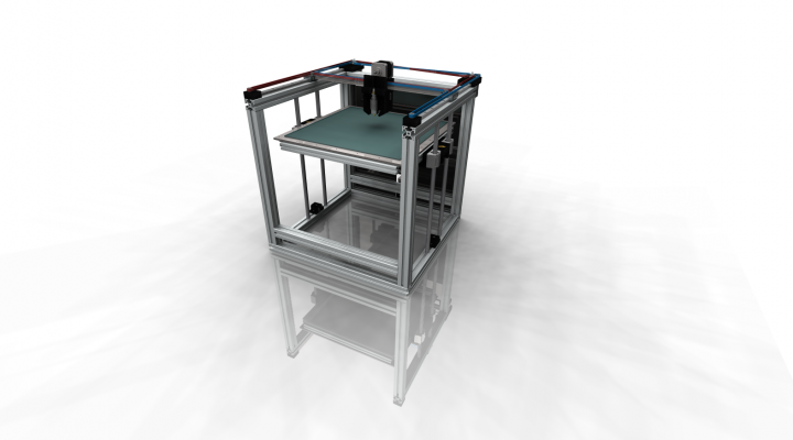
Here are two pictures of the motion system. Nothing fancy, it is a standard CoreXY setup with crossing belts etc. I have an aluminum "arm" connecting the Y-axis carriages on which I mount the X-axis rail. Haven't really made up my mind whether it is a good solution yet as it doesn't provide much rigidity in Z, but it makes sure that the Y carriages do not get pulled together by the belt drive. It doesn't feel right to only use the linear rail for carrying the effector, but maybe a u-profile (or t-slot extrusion) would do a better job than a flat aluminum piece.. A t-extrusion would also be a more reprapable solution!
I am happy with how compact it is, the not-printable volume inside the frame is almost only dictated by the size of the effector carriage itself. Right now it seems like the frame outside dimensions will be 400x460x460 mm (+ motors on backside) and the printable volume 340x340x320 mm. The half open frame structure will probably also make it look less bulky.
I have ordered much of the mechanical parts now, hopefully I can start building it in a few weeks!
Some activities coming up are:
Edited 1 time(s). Last edit at 01/29/2016 09:20AM by robkar.
My Delta Printer: [www.thingiverse.com]
I am happy with how compact it is, the not-printable volume inside the frame is almost only dictated by the size of the effector carriage itself. Right now it seems like the frame outside dimensions will be 400x460x460 mm (+ motors on backside) and the printable volume 340x340x320 mm. The half open frame structure will probably also make it look less bulky.


I have ordered much of the mechanical parts now, hopefully I can start building it in a few weeks!
Some activities coming up are:
- Finalize effector carriage design (adding belt clamps and
- Integrate hidden wire channels behind side panels
- Add endstop mounts
- Finalize bed assembly design (leveling, heater, wiring)
- Design cabinet for electronics (will put a panel on the backside on which a mount a small cabinet that will house the electronics)
- Decide what electronics to go for (go cheap with Ramps VS semicheap Duet 0.6?)
- Select power supply (and whether to put it in the printer or on the floor)
- Order more stuff, like electronics
- If needed, get aluminum part machined
- And all the other things I have forgot about..
Edited 1 time(s). Last edit at 01/29/2016 09:20AM by robkar.
My Delta Printer: [www.thingiverse.com]
|
Re: New printer build! My CoreXY. February 02, 2016 05:23PM |
Registered: 8 years ago Posts: 24 |
The project drawer is not empty any more! I get parts from China delivered every day now, it's like christmas
I did also finally make up my mind regarding electronics and ordered a Duet board + a 24V power supply!
One (stupid) question: If not using a bed leveling sensor on the effector, where should I put my Z end stop? What is common sense? At min position (max print height)? I would have to travel the whole Z height for each homing, but it would also be the "safest" solution since no prints can get crushed etc. A max Z endstop would also have to be adjusted quite carefully in order to set up the correct nozzle-to-bed distance?
My Delta Printer: [www.thingiverse.com]
|
Re: New printer build! My CoreXY. February 03, 2016 12:28AM |
Registered: 8 years ago Posts: 67 |
Well, in my opinion, (keeping in mind I haven't built anything yet) As long as you can get repeatable results, you could use some screw to trigger the maxZ switch, and adjust that screw pretty close. Then do the rest with bed leveling...
Edit: might have mixed up max and min positions, but you get the idea
Edited 1 time(s). Last edit at 02/03/2016 02:00AM by Dalius98.
Edit: might have mixed up max and min positions, but you get the idea
Edited 1 time(s). Last edit at 02/03/2016 02:00AM by Dalius98.
|
Re: New printer build! My CoreXY. February 03, 2016 12:42AM |
Registered: 11 years ago Posts: 5,780 |
Releasing parts from the bed: glass is a problem. It can break and cut you. Why use glass, a thermal insulator, when your goal is to have even temperature over the surface of the build plate? Use aluminum. If a part doesn't want to come loose, you can always convince it to let go with a rubber mallet- I have done so many times! All aluminum is not created equal. You want cast tooling plate because it comes milled flat. It works.
Z axis limit switch: you need a switch at the z=0 position, a switch at z=max is optional. The switch can be mounted on the printer's frame so that a screw attached to the moving part of the Z axis support structure actuates it.
Ultra MegaMax Dominator 3D printer: [drmrehorst.blogspot.com]
Z axis limit switch: you need a switch at the z=0 position, a switch at z=max is optional. The switch can be mounted on the printer's frame so that a screw attached to the moving part of the Z axis support structure actuates it.
Ultra MegaMax Dominator 3D printer: [drmrehorst.blogspot.com]
|
Re: New printer build! My CoreXY. February 03, 2016 03:34AM |
Registered: 10 years ago Posts: 14,672 |
DD doesn't like glass bed plates. I do. The advantages are:
1. It is much harder than aluminium, so less likely to be damaged if the print head crashes into it and drags along it.
2. If it does get damaged, it is easy and cheap to replace.
3. At the end of a print, a thick cast aluminium bed will take a long time to cool down (even my 6mm aluminium bed plate takes about 20 minutes). Until the print is cool enough to release it from the bed, you can't use the printer. When my prints finish, I remove the glass bed plate and stack it vertically to cool down quickly. Meanwhile I can start another print on a new bed plate.
4. If the print is difficult to release from the bed, I can put the bed+print in the fridge or freezer to make it easier to separate them.
5. I have beds prepared with different surface coatings for printing different materials.
Yes glass is not a good conductor of heat (although if it were really an insulator then we wouldn't need double glazed windows), so I need to add about 5C to the bed temperature I select when printing PLA, and 10C when printing ABS (that's for 4mm glass).
If I built a very large printer then I wouldn't use glass because of the difficulty of handling it.
Large delta printer [miscsolutions.wordpress.com], E3D tool changer, Robotdigg SCARA printer, Crane Quad and Ormerod
Disclosure: I design Duet electronics and work on RepRapFirmware, [duet3d.com].
|
Re: New printer build! My CoreXY. March 06, 2016 04:19PM |
Registered: 8 years ago Posts: 24 |
Not much activity here lately! I have been busy with life you know, but this weekend I got some time off to actually do something useful
While I have been not building anything, a friend of mine has machined the few aluminum parts I'll need for my build (X gantry + bed) and most of what I have ordered from China has arrived. I have now done a test and assembled the frame, the X-Y rails and the Z axis lift.
So far so good! No big problems yet, the alignment of everything went quite well I think. The frame is stable enough and the XY motion is pretty smooth. The super cheap lead screws I got were very skew, so while the bed can move freely I suspect it might cause problems when/if it's gonna print something. Might have to look into buying better screws..
I am still waiting for some small components to arrive before I can continue, I also need to finish the effector design. Regarding the bed my first attempt will be to use a piece of glass (320x320mm) with a sheet of PEI on top. I wanna see what the PEI hype is all about!
My Delta Printer: [www.thingiverse.com]
While I have been not building anything, a friend of mine has machined the few aluminum parts I'll need for my build (X gantry + bed) and most of what I have ordered from China has arrived. I have now done a test and assembled the frame, the X-Y rails and the Z axis lift.
So far so good! No big problems yet, the alignment of everything went quite well I think. The frame is stable enough and the XY motion is pretty smooth. The super cheap lead screws I got were very skew, so while the bed can move freely I suspect it might cause problems when/if it's gonna print something. Might have to look into buying better screws..

I am still waiting for some small components to arrive before I can continue, I also need to finish the effector design. Regarding the bed my first attempt will be to use a piece of glass (320x320mm) with a sheet of PEI on top. I wanna see what the PEI hype is all about!
My Delta Printer: [www.thingiverse.com]
|
Re: New printer build! My CoreXY. April 19, 2016 02:04AM |
Registered: 8 years ago Posts: 24 |
Long time no see, but I managed to play around with this thing over the weekend. It is now moving!
YOUTUBE
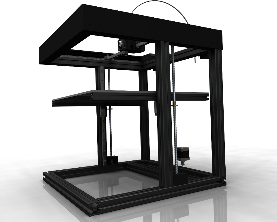
From my last post I have changed the Z-axis, from two linear guides into four smooth rods and metal housed bearings. My design with the linear guides consisted of too much plastic, so there was noticeable flex going on. The smooth rods seem fine though, I just had to de-couple the nuts so that my bent lead screws were allowed to wobble.
I have also skipped the non-boxy design (I built it at first, then decided I wanted to be able to enclose it further on).
More to come...
My Delta Printer: [www.thingiverse.com]
YOUTUBE
From my last post I have changed the Z-axis, from two linear guides into four smooth rods and metal housed bearings. My design with the linear guides consisted of too much plastic, so there was noticeable flex going on. The smooth rods seem fine though, I just had to de-couple the nuts so that my bent lead screws were allowed to wobble.
I have also skipped the non-boxy design (I built it at first, then decided I wanted to be able to enclose it further on).
More to come...
My Delta Printer: [www.thingiverse.com]
|
Re: New printer build! My CoreXY. April 19, 2016 03:49AM |
Registered: 10 years ago Posts: 179 |
|
Re: New printer build! My CoreXY. May 21, 2016 04:21AM |
Registered: 8 years ago Posts: 24 |
Quote
Edvardas
Why not put Z-axis smooth rods further away from each other to the corners of the bed? That should make it even more stable.
I think I am correct now, but my engineering guts tell me that the load (ie. the lead screw) should be placed as close to the rail as possible in order to avoid binding. In theory my Z-system is already overconstrained..
|
Re: New printer build! My CoreXY. May 21, 2016 04:56AM |
Registered: 8 years ago Posts: 24 |
The build is proceeding pretty slow, which is OK for me.
Anyhow, I built the frame, designed an effector, hooked everything up and it almost immediately worked alright. Apart from the Z-bed probe, I had positioned it too far away from the bed (and without adjustment possibilities, stupid).
As you can see I changed my mind on several aspects compared to my initial plan. First I opted for direct drive extruder capability. I have my bowden style delta (which works fantastic), so I thought it could be fun to try something else in this machine. I have also found some interesting applications for flexible materials. The extruder stepper can easily be disassembled from the carriage, if I would like to switch to bowden for speed-reasons.
I also skipped my "open frame" and made the machine into a cube. It works nicely and is super rigid, but I still have a feeling that it is freakin boring, another aluminum extrusion cube you know. This is why I am now switching to another belt path, which allows me to move the front, top aluminum bar so that the print bed is very reachable:
This concept also means using to less pulleys and simpler brackets. I am using the Nema 17 mounting holes for attaching the pulleys, this goes hand in hand with how I use the MGN12 carriage holes for mounting the pulley there. Since I want to minimize the custom machined parts, this is a way to attach things to metal pieces that are already there.
If the frame is not rigid enough like this, it is a 2 minute procedure to move the front bar back. I will also attach panels to the side of the printer, which will add rigidity. I have also redesigned my effector to use 10mm thick blowers instead of 20 mm, it was a little bit too big for my taste. The belt tensioning mechanism I have works really good, will show more on that in a later post.
I will now also tap the aluminum extrusion ends, and use that to screw the whole thing together. In that way I only need to use brackets where really necessary. More updates to come!
Anyhow, I built the frame, designed an effector, hooked everything up and it almost immediately worked alright. Apart from the Z-bed probe, I had positioned it too far away from the bed (and without adjustment possibilities, stupid).


As you can see I changed my mind on several aspects compared to my initial plan. First I opted for direct drive extruder capability. I have my bowden style delta (which works fantastic), so I thought it could be fun to try something else in this machine. I have also found some interesting applications for flexible materials. The extruder stepper can easily be disassembled from the carriage, if I would like to switch to bowden for speed-reasons.
I also skipped my "open frame" and made the machine into a cube. It works nicely and is super rigid, but I still have a feeling that it is freakin boring, another aluminum extrusion cube you know. This is why I am now switching to another belt path, which allows me to move the front, top aluminum bar so that the print bed is very reachable:


This concept also means using to less pulleys and simpler brackets. I am using the Nema 17 mounting holes for attaching the pulleys, this goes hand in hand with how I use the MGN12 carriage holes for mounting the pulley there. Since I want to minimize the custom machined parts, this is a way to attach things to metal pieces that are already there.
If the frame is not rigid enough like this, it is a 2 minute procedure to move the front bar back. I will also attach panels to the side of the printer, which will add rigidity. I have also redesigned my effector to use 10mm thick blowers instead of 20 mm, it was a little bit too big for my taste. The belt tensioning mechanism I have works really good, will show more on that in a later post.


I will now also tap the aluminum extrusion ends, and use that to screw the whole thing together. In that way I only need to use brackets where really necessary. More updates to come!
|
Re: New printer build! My CoreXY. May 21, 2016 05:20AM |
Registered: 8 years ago Posts: 776 |
Quote
robkar
Not much activity here lately! I have been busy with life you know, but this weekend I got some time off to actually do something useful
Quote
While I have been not building anything, a friend of mine has machined the few aluminum parts I'll need for my build (X gantry + bed) and most of what I have ordered from China has arrived. I have now done a test and assembled the frame, the X-Y rails and the Z axis lift.
looks pretty beefy and sturdy
Quote
So far so good! No big problems yet, the alignment of everything went quite well I think. The frame is stable enough and the XY motion is pretty smooth. The super cheap lead screws I got were very skew, so while the bed can move freely I suspect it might cause problems when/if it's gonna print something. Might have to look into buying better screws..
can i suggest alfa-tech3d.com TR8 lead screws then put a GT2-50 on them (i 3d-printed one, grab the source here [hands.com]) and used a GT2-16, then a 900mm closed loop. also, i know people like doing the mid-supported printbed idea, but it's nowhere near as good as adding that one extra lead screw. the analysis is as follows:
- you need to ensure six things: (1) free and precise motion in Z (2) fixed in X (3) fixed in Y, (4) zero ROTATION about x-axis, (5) zero ROTATION about y-axis (6) zero ROTATION about z-axis
- 1 z rail can NOT fulfil the constraints. 1 z rail will only ensure that linear motion is free in Z (1) but will NOT prevent X or Y (2) and (3) and will NOT constrain rotation in ANY significantly-accurate way (3) (4) or (5).
- z rails 1 and 2 ensure that linear motion is free in Z (1) but fixed in X and Y (2) and (3). they do NOT constrain rotation about the line BETWEEN the two rails (4) or (5). they DO constrain rotation about the z-axis (6).
- additional z rails are unnecessary because they do not add anything that 2 z rails can already achieve.
- 2 lead screws do NOT and CANNOT fulfil the constraints. 2 lead screws only fulfil constraints (1) and in the design you've created will also fulfil constraint (4) but will NOT fulfil constraint (5).
- 3 lead screws ensure that the exact same Z motion is achieved as a plane, providing the up-down travel needed as well as completely stopping rotation, thus fulfilling constraints (1) as well as (3), (4) and (5). they do NOT constrain sideways motion (2) or (3).
- when 2 z-rails and 3 lead screws are used, the combination adds up to fulfilling all 6 required constraints, thus giving an unbelievably rock-solid system which in no way relies on leverage or structural strength of parts
is that clear enough as to why you should consider using triple lead screws and dual z rails? if you don't, you're relying instead on the materials and the parts to stop rotation on at least one axis (X-axis in the case of the design that you've made), via a lever effect about those materials, as well as relying on the machine tolerances of the linear bearings. sure you could reduce the probability of that rotation from happening by only ever printing right in the middle of the printbed, and not going too far back or forwards with too heavy an object to print, but... for the sake of $25 for another lead screw, a closed loop belt and so on when you've gone to all this trouble to make a really strong frame and everything else....
the only other requirement is that the deflection (springiness) of the printbed itself must be within acceptable bounds, and i believe you did a damn good job of analysing the actual material there, and have selected a thick enough plate to meet that.
Quote
[attachment 74015 IMG_0325.jpg]
I am still waiting for some small components to arrive before I can continue, I also need to finish the effector design. Regarding the bed my first attempt will be to use a piece of glass (320x320mm) with a sheet of PEI on top. I wanna see what the PEI hype is all about!
is that from mutley3d.com? if so, he's pretty busy as it's gone completely mad, he's getting loads of orders so there must be something to it whilst you're there, you might want to consider looking at the Flex3Drive as well. it's unique in the 3d-printing world, utterly unique, and gives you *more* than the best of both worlds from the direct and bowden designs.also, the only other thing i would say, that's extremely beefy frame, but why use those tiny 20x20 corner supports? if you went to 20x40 or could find some 40x40 you'd find that the frame stiffened up considerably. worth a thought? motedis.com have a huge range of stuff that's not very expensive, and they're in europe.
-- sandwich200: compact portable folding corexy printer [reprap.org]
|
Re: New printer build! My CoreXY. May 21, 2016 05:34AM |
Registered: 8 years ago Posts: 776 |
Quote
robkar
I also skipped my "open frame" and made the machine into a cube. It works nicely and is super rigid, but I still have a feeling that it is freakin boring, another aluminum extrusion cube you know.
awwwww
i really liiked that Quote
[attachment 78438 image3.png]
ooo whoawhoawhoa, hangonhangon, ok hmmm that attachment might not come through let me do a link instead
ok look there right at the back, in the middle, the red and the blue belt CROSS and occupy the SAME SPACE. that's not gonna work
what you'll need to do is to lift either the entire x or the entire y - don't be tempted to like do a half-way house by dropping or raising *some* of the x idlers or *some* of the y idlers, make *absolutely* sure you keep all idlers/belts/gears for each axis in the same plane, ok?
lift one so that it's 10mm above the other, and things will be fine, ok? ok 10mm if you have 6mm belts - you want there to be about 2-3mm between the top of one belt and the bottom edge of the other. so if you've got 8mm belts make it... a 12mm raise (is that right?) then you can look at stacking the bearings on top of each other, maybe use the same bolt in some places (on the x-ends) you'll have to work it out. take a look at the Fusebox, the Sandwich200 and Ax's FB2020. they all use this "offset" stacked belt arrangement.
other than that, the belt lines themselves are perfect. i can see from the other images that you've got the bits of belt that vary in length lined up so that they stay on the same line (this is really important) so you've got that aspect right.... yeah.
-- sandwich200: compact portable folding corexy printer [reprap.org]
|
Re: New printer build! My CoreXY. May 21, 2016 06:28AM |
Registered: 8 years ago Posts: 776 |
Quote
robkar
I also skipped my "open frame" and made the machine into a cube. It works nicely and is super rigid, but I still have a feeling that it is freakin boring, another aluminum extrusion cube you know. This is why I am now switching to another belt path, which allows me to move the front, top aluminum bar so that the print bed is very reachable:
eek! don't miss out that top front bar! what it does (when you have the triangle corner-braces in the top face and the front face) is, it stops the left and right faces rotating. to test this, do the following:
- find a dead-level piece of floor or a dead-level workbench
- place the frame on it and make sure all 4 corners are absolutely dead-flat: no "wobble".
- hold the left bottom extrusion piece down flat on the ground so that the back left and front left corners stay FIXED to the ground.
- pin the BACK RIGHT corner as well. use g-clamps on a workbench, or get a friend to help hold it down.
- lift the FRONT RIGHT corner
what you will find is that that front right corner comes clean off the ground. i'm guessing that with very little effort (i.e. very little force) you should be able to lift it by at least....... 3 to 4 millimetres. even 0.5mm is far too much, because that 0.5mm will translate DIRECTLY into +/- 0.5mm of movement in the printhead. that's 500 microns when you're developing a precision engineering tool with around a 5 micron resolution! 2 orders of magnitude out!
even if you try to put in corner-braces onto that lower bar, you can't fit any horizontally (which is critical) because there's no left and right horizontal bars going back in that same plane. corner-braces onto the uprights won't help because the "lever" effect will render them useless. if you grab the top left and top right corners and pull them apart or push them together, that's the "lever" effect which will be reduced and finally eliminated the further up you put that bar.
the original design that you had was much much better for structural integrity.
Edited 1 time(s). Last edit at 05/21/2016 06:29AM by lkcl.
|
Re: New printer build! My CoreXY. May 21, 2016 06:08PM |
Registered: 8 years ago Posts: 24 |
Wow lkcl, what a response! Where to start?
These are good points, I understand that my bed is levered around my X-axis. I have been considering a three point Z-axis before, I have this hidden in my CAD assembly:
This exact belt path will not work though, one of the screws will rotate the wrong direction But it can be solved by putting an idler or two close to the motor / back screw, so that it rotates in the same direction as the others. The orange rods are 8mm lead screws, the grey ones are 12mm smooth rods. The belt here is actually 1750 mm long.. Will the elasticity (assuming standard China-made GT2 belt) cause any problems? Like in syncing the screws?
Based on my initial tests of my current setup the bearings make it pretty solid anyhow, so I will probably do some test prints before modifying it (I only have two lead screws at hands atm, need to order and wait for one more to arrive to test the three point concept.. ) One should also remember, many printers do just fine with completely cantilevered beds, bearings exist for a reason
This is also mostly true. But I will not remove the front top bar completely, just move it down in order for the bed to be very accessible. I did also write that if it is not rigid enough, it is SUPER easy to move back to the top position. Since you built a foldable printer I am pretty sure you can understand that there are reasons for not building the optimal machine from a structural mechanics point of view. My reason is that I want something that looks cool, is easy to work with and a little bit different. Yours was that you wanted it to be foldable!
Edited 2 time(s). Last edit at 05/21/2016 07:56PM by robkar.
Quote
lkcl
can i suggest alfa-tech3d.com TR8 lead screws then put a GT2-50 on them (i 3d-printed one, grab the source here [hands.com]) and used a GT2-16, then a 900mm closed loop. also, i know people like doing the mid-supported printbed idea, but it's nowhere near as good as adding that one extra lead screw. the analysis is as follows:
you need to ensure six things: (1) free and precise motion in Z (2) fixed in X (3) fixed in Y, (4) zero ROTATION about x-axis, (5) zero ROTATION about y-axis (6) zero ROTATION about z-axis
1 z rail can NOT fulfil the constraints. 1 z rail will only ensure that linear motion is free in Z (1) but will NOT prevent X or Y (2) and (3) and will NOT constrain rotation in ANY significantly-accurate way (3) (4) or (5).
z rails 1 and 2 ensure that linear motion is free in Z (1) but fixed in X and Y (2) and (3). they do NOT constrain rotation about the line BETWEEN the two rails (4) or (5). they DO constrain rotation about the z-axis (6).
additional z rails are unnecessary because they do not add anything that 2 z rails can already achieve.
2 lead screws do NOT and CANNOT fulfil the constraints. 2 lead screws only fulfil constraints (1) and in the design you've created will also fulfil constraint (4) but will NOT fulfil constraint (5).
3 lead screws ensure that the exact same Z motion is achieved as a plane, providing the up-down travel needed as well as completely stopping rotation, thus fulfilling constraints (1) as well as (3), (4) and (5). they do NOT constrain sideways motion (2) or (3).
when 2 z-rails and 3 lead screws are used, the combination adds up to fulfilling all 6 required constraints, thus giving an unbelievably rock-solid system which in no way relies on leverage or structural strength of parts
is that clear enough as to why you should consider using triple lead screws and dual z rails? if you don't, you're relying instead on the materials and the parts to stop rotation on at least one axis (X-axis in the case of the design that you've made), via a lever effect about those materials, as well as relying on the machine tolerances of the linear bearings. sure you could reduce the probability of that rotation from happening by only ever printing right in the middle of the printbed, and not going too far back or forwards with too heavy an object to print, but... for the sake of $25 for another lead screw, a closed loop belt and so on when you've gone to all this trouble to make a really strong frame and everything else....
the only other requirement is that the deflection (springiness) of the printbed itself must be within acceptable bounds, and i believe you did a damn good job of analysing the actual material there, and have selected a thick enough plate to meet that.
These are good points, I understand that my bed is levered around my X-axis. I have been considering a three point Z-axis before, I have this hidden in my CAD assembly:


This exact belt path will not work though, one of the screws will rotate the wrong direction
But it can be solved by putting an idler or two close to the motor / back screw, so that it rotates in the same direction as the others. The orange rods are 8mm lead screws, the grey ones are 12mm smooth rods. The belt here is actually 1750 mm long.. Will the elasticity (assuming standard China-made GT2 belt) cause any problems? Like in syncing the screws?Based on my initial tests of my current setup the bearings make it pretty solid anyhow, so I will probably do some test prints before modifying it (I only have two lead screws at hands atm, need to order and wait for one more to arrive to test the three point concept.. ) One should also remember, many printers do just fine with completely cantilevered beds, bearings exist for a reason
Quote
lkcl
eek! don't miss out that top front bar! what it does (when you have the triangle corner-braces in the top face and the front face) is, it stops the left and right faces rotating. to test this, do the following:
- find a dead-level piece of floor or a dead-level workbench
- place the frame on it and make sure all 4 corners are absolutely dead-flat: no "wobble".
- hold the left bottom extrusion piece down flat on the ground so that the back left and front left corners stay FIXED to the ground.
- pin the BACK RIGHT corner as well. use g-clamps on a workbench, or get a friend to help hold it down.
- lift the FRONT RIGHT corner
what you will find is that that front right corner comes clean off the ground. i'm guessing that with very little effort (i.e. very little force) you should be able to lift it by at least....... 3 to 4 millimetres. even 0.5mm is far too much, because that 0.5mm will translate DIRECTLY into +/- 0.5mm of movement in the printhead. that's 500 microns when you're developing a precision engineering tool with around a 5 micron resolution! 2 orders of magnitude out!
even if you try to put in corner-braces onto that lower bar, you can't fit any horizontally (which is critical) because there's no left and right horizontal bars going back in that same plane. corner-braces onto the uprights won't help because the "lever" effect will render them useless. if you grab the top left and top right corners and pull them apart or push them together, that's the "lever" effect which will be reduced and finally eliminated the further up you put that bar.
the original design that you had was much much better for structural integrity.
This is also mostly true. But I will not remove the front top bar completely, just move it down in order for the bed to be very accessible. I did also write that if it is not rigid enough, it is SUPER easy to move back to the top position. Since you built a foldable printer I am pretty sure you can understand that there are reasons for not building the optimal machine from a structural mechanics point of view. My reason is that I want something that looks cool, is easy to work with and a little bit different. Yours was that you wanted it to be foldable!
Edited 2 time(s). Last edit at 05/21/2016 07:56PM by robkar.
|
Re: New printer build! My CoreXY. May 21, 2016 06:12PM |
Registered: 8 years ago Posts: 24 |
Quote
lkcl
[attachment 78438 image3.png]
ooo whoawhoawhoa, hangonhangon, ok hmmm that attachment might not come through let me do a link instead
ok look there right at the back, in the middle, the red and the blue belt CROSS and occupy the SAME SPACE. that's not gonna work
what you'll need to do is to lift either the entire x or the entire y - don't be tempted to like do a half-way house by dropping or raising *some* of the x idlers or *some* of the y idlers, make *absolutely* sure you keep all idlers/belts/gears for each axis in the same plane, ok?
lift one so that it's 10mm above the other, and things will be fine, ok? ok 10mm if you have 6mm belts - you want there to be about 2-3mm between the top of one belt and the bottom edge of the other. so if you've got 8mm belts make it... a 12mm raise (is that right?) then you can look at stacking the bearings on top of each other, maybe use the same bolt in some places (on the x-ends) you'll have to work it out. take a look at the Fusebox, the Sandwich200 and Ax's FB2020. they all use this "offset" stacked belt arrangement.
other than that, the belt lines themselves are perfect. i can see from the other images that you've got the bits of belt that vary in length lined up so that they stay on the same line (this is really important) so you've got that aspect right.... yeah.
Well, If you look around I am pretty sure you will find many coreXY printers where the belts are crossed like that. I have it like that on my current setup, look at the photographs in my previous posts.The belts are rotated 180 degrees and there is no problem at all.. I want to keep them on the same level.
|
Re: New printer build! My CoreXY. May 21, 2016 08:07PM |
Registered: 8 years ago Posts: 776 |
Quote
robkar
Well, If you look around I am pretty sure you will find many coreXY printers where the belts are crossed like that. I have it like that on my current setup, look at the photographs in my previous posts.The belts are rotated 180 degrees and there is no problem at all.. I want to keep them on the same level.
yeah i can see why keeping the belts on the same level is an advantage: keep them centred or as close as possible to the line of the bearings, avoids torquing the linear bearings/rails. however the moment you go off-plane you end up with the top edge of the belt being a different length and tension from the bottom edge, and the belt trying to unscrew itself off the idlers and all sorts of orrible things. i started from the Fusebox, and, in my mind, i felt that the tradeoff of advantages / disadvantages was in favour of the Fusebox approach. *but*, i *didn't* like the way the Fusebox belts attach to the carriage to cause rotation about the z-axis of the carriage (prevented only by grinding the linear bearings against the bar). so i tried fixing that... caused other problems whoops.... it's a never-ending thing this
|
Re: New printer build! My CoreXY. May 21, 2016 08:31PM |
Registered: 8 years ago Posts: 24 |
Quote
lkcl
Quote
robkar
Well, If you look around I am pretty sure you will find many coreXY printers where the belts are crossed like that. I have it like that on my current setup, look at the photographs in my previous posts.The belts are rotated 180 degrees and there is no problem at all.. I want to keep them on the same level.
yeah i can see why keeping the belts on the same level is an advantage: keep them centred or as close as possible to the line of the bearings, avoids torquing the linear bearings/rails. however the moment you go off-plane you end up with the top edge of the belt being a different length and tension from the bottom edge, and the belt trying to unscrew itself off the idlers and all sorts of orrible things. i started from the Fusebox, and, in my mind, i felt that the tradeoff of advantages / disadvantages was in favour of the Fusebox approach. *but*, i *didn't* like the way the Fusebox belts attach to the carriage to cause rotation about the z-axis of the carriage (prevented only by grinding the linear bearings against the bar). so i tried fixing that... caused other problems whoops.... it's a never-ending thing this
Hehe yes. To be honest, most of the stuff I print is actually new parts for my 3D printer! This is the fun part, testing new stuff etc.

Sorry, only registered users may post in this forum.