appjaws-D-Bot progress
Posted by appjaws1
|
appjaws-D-Bot progress April 21, 2016 02:57AM |
Registered: 10 years ago Posts: 780 |
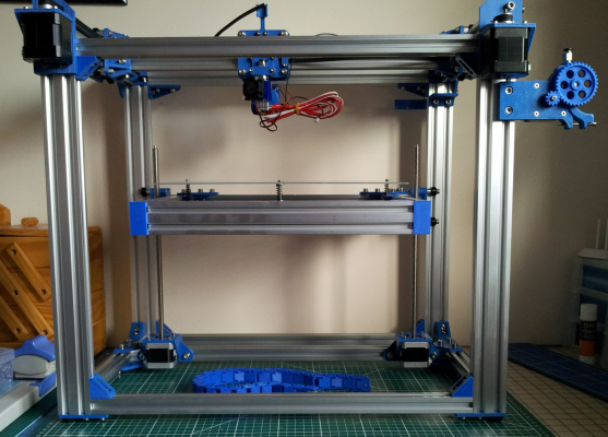
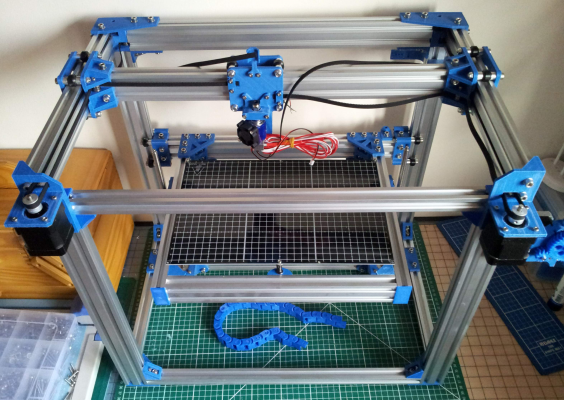
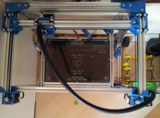
Just thought I would share my build experience so far.
Thanks to the_digital_dentist for the suggestion of 3 point bed levelling, which I have implemented.
I have silicone hight temperature glue on order to glue cork sheet to the underside of the bed heater for insulation.
I cut the extrusions as per the guide in the instructions and built the frame without any problems.
I had decided that I would use 2 stepper motors, connected in series, for the bed lift and bought motors with lead screws already fitted.
As soon as I tried to fit them I realised that the bed would not reach the hot end nozzle. The lead screws were 290 mm long but the frame was designed for 400 mm lead screws.Rather than go to the expense of ordering new motors and longer screws I decided to lower the height of the frame by 80 mm. My current printer, an Ormerod, has a build height of 180 mm, which I have never used in 2 years
I have now ended up with a build size of 300 x 200 x 260 mm which is ample of me.
appjaws - Core XYUV Duet Ethernet Duex5
firmware 3.1.1 Web Interface 3.1.1
Ormerod 1-converted to laser engraver, Duet wifi
OpenSCAD version 2020.07
slic3r-1.3.0, Simplify3D 4.1.2, Cura-4.4.1
|
Re: appjaws-D-Bot progress April 21, 2016 11:12AM |
Registered: 8 years ago Posts: 12 |
|
Re: appjaws-D-Bot progress April 24, 2016 09:43AM |
Registered: 8 years ago Posts: 622 |
That's looking good. I'm looking to build another printer but my main requirement over the Mendel3 I have at the moment is extra height (a lot of extra height). I looked at Delta designs but I'm using a Diamond hot end so mounting the 3 extruders while keeping Bowden tube lengths manageable becomes difficult. It strikes me that a corexy design might be the way to go. I don't have the skills to design anything from scratch but it strikes me that taking something like a D Bot or Eclips3d kit and scaling up the height wouldn't be too difficult. It'd just mean longer uprights and lead screws as well as longer and thicker Z guides would it not? Of course, there are the usual caveats about stiffness etc but looking at your pics, it doesn't seem to be too difficult to add diagonal bracing and/or chunkier corner barckets. Is this a feasible idea or have I missed something? I know nothing about corexy printers apart from what I have read on these forums over the last week or 2.
|
Re: appjaws-D-Bot progress April 24, 2016 01:34PM |
Registered: 8 years ago Posts: 776 |
Quote
deckingman
That's looking good.
yeah, agreed. simple, straightforward, love the blue, and love the large section aluminium. using delrin runners for the z bed is a great idea, too. i'm using 15x15 and it's possible to bend a 1m section by hand. i'll go with 20x20 for a future revision, for sure.
Quote
It'd just mean longer uprights and lead screws as well as longer and thicker Z guides would it not?
yep, longer uprights and lead screws - pretty straightforward there. and this design is using delrin runners, which i'm not familiar with (i'm using rods, and have made the mistake of using 8mm, currently upgrading to 12mm), but i should imagine it'd be fine. if the bed was 300mm deep i'd be slightly concerned, because those delrin runners look like they're only separated by about... what... 40mm? and, eek! zooming in, they're into plastic! i'd be rather concerned about that - PLA has a habit of being fine until it just goes "snap", and it's also susceptible to temperature.
Quote
Of course, there are the usual caveats about stiffness etc but looking at your pics, it doesn't seem to be too difficult to add diagonal bracing and/or chunkier corner barckets. Is this a feasible idea or have I missed something? I know nothing about corexy printers apart from what I have read on these forums over the last week or 2.
it's down to materials science. plastic is totally inadequate for any kind of structural strength at the kinds of distances we're making 3d printers at. it's a lever-effect: the longer the span, the greater the structural weakness of the material (plastic, in this case) becomes apparent. and, if like me, you've ever printed a long part and bent it with one hand, you'd ould know for absolute dead-certain that it would be foolish to think that PLA is in any way adequate for the job of stiffening a frame, especially at a distance of 400 to 500mm.
basically you want metal bracing or some other method (i use several, including filling in the frame with hardboard, mounted at 16 (sixteen!) places per board). alfa-tech3d have just got in some 20x20 section and have the right kind of metal corner braces that you'll need - or you can find someone with a Ltd Company and order the same equivalent bits from Misumi. or look on the openbuilds web site, they'll have plenty of stuff there. another extremely effective way to do it is this: [forums.reprap.org] - then you don't need to rely on the plastic corners at all, they'll just be there to hold stuff like motors, bearings etc. which is fine.
about corexy: this guy gives a really, really good explanation: [www.doublejumpelectric.com] and he also does a detailed walk-through of the various revisions that he made. key details are: for goodness sake keep the belts at right-angles when they come out of the x-ends, and keep each belt in its own plane. don't be tempted to "dip" the belt down by offsetting any of the bearings or the motor gear. if you follow those rules you'll come out with an accurate printer.
|
Re: appjaws-D-Bot progress April 24, 2016 03:38PM |
Registered: 8 years ago Posts: 622 |
All good stuff. That's very encouraging and thanks for the links.
Although I build garden decks for a living these days, this is career number 5 (or 6 or 7 - I've changed tack so many times I've kind of lost count). However, when I first started work in 1969, it was as an apprentice tool maker and I spent about 30 years as an automotive engineer in one form or another. Although that was a very long time ago, I still remember basic engineering principles so I think I could cobble together something that is stiff enough. Of course, my day job is designing and building structures that are stiff and strong and subject to loads of up to a couple of tons (or more), but they are made from 4.8 metre lengths of timber and they are allowed to flex a bit, so not quite the same thing.
What I don't have is access to metal working machinery. What I do have is a 3d printer so if I can use a plastic part, I will. After all this is the RepRap forum. I was thinking along the lines of plastic corners just to hold the pieces together but with metal bracing going from top left to bottom right, and top right to bottom left on each side of the frame to take any loads or twisting forces. Just flat strip would do.That way, there wouldn't be any significant loading on the plastic parts. Of course, the front would need to be left open to get the printed part out so some other arrangement would be needed on that face.
I don't like the idea of a cantilevered bed though. It just sort of goes against grain somehow. I think I'd be looking at maybe 3 lead screws or some such arrangement. Lots to think about......
Edited 1 time(s). Last edit at 04/24/2016 03:39PM by deckingman.
|
Re: appjaws-D-Bot progress April 24, 2016 07:22PM |
Registered: 10 years ago Posts: 14,672 |
Quote
deckingman
That's looking good. I'm looking to build another printer but my main requirement over the Mendel3 I have at the moment is extra height (a lot of extra height). I looked at Delta designs but I'm using a Diamond hot end so mounting the 3 extruders while keeping Bowden tube lengths manageable becomes difficult.
The Bowden tubes on a 3-extruder delta don't need to be any longer than on a single-extrusion delta. OTOH if you were thinking of using a flying extruder, that would be more difficult with 3 extruders.
Large delta printer [miscsolutions.wordpress.com], E3D tool changer, Robotdigg SCARA printer, Crane Quad and Ormerod
Disclosure: I design Duet electronics and work on RepRapFirmware, [duet3d.com].
|
Re: appjaws-D-Bot progress April 24, 2016 07:59PM |
Registered: 8 years ago Posts: 776 |
Quote
deckingman
All good stuff. That's very encouraging and thanks for the links.
Although I build garden decks for a living these days, this is career number 5 (or 6 or 7 - I've changed tack so many times I've kind of lost count). However, when I first started work in 1969, it was as an apprentice tool maker and I spent about 30 years as an automotive engineer in one form or another. Although that was a very long time ago, I still remember basic engineering principles so I think I could cobble together something that is stiff enough. Of course, my day job is designing and building structures that are stiff and strong and subject to loads of up to a couple of tons (or more), but they are made from 4.8 metre lengths of timber and they are allowed to flex a bit, so not quite the same thing.
cooool
 well, yeah, metal flexes as well, but just not as much. no that sounds like you have the perfect expertise to think about how to construct a really good frame.
Quote
What I don't have is access to metal working machinery.
neither do i, which is the main reason why i picked the Fusebox to start from. you can get Misumi extrusions off-the-shelf including brackets (if you have a company) - but i just got makerbeam 1m section, an angle-grinder and a 125x1mm disc (many people just use a hacksaw and a file), and then got some of these [www.ebay.co.uk] - people are finding ways, y'know?
but the nice thing about the misumi extrusion, and the way that the Fusebox is put together (and the printer i designed, as well), you don't need any specialist tools. it's all nuts and bolts. i use pliers, not a spanner... don't tell no-one..

Quote
What I do have is a 3d printer so if I can use a plastic part, I will. After all this is the RepRap forum. I was thinking along the lines of plastic corners just to hold the pieces together but with metal bracing going from top left to bottom right, and top right to bottom left on each side of the frame to take any loads or twisting forces. Just flat strip would do.
yeahhh i've worked in the building trade, too: i thought about that, but i wondered how the two strips could be tied together in sufficient tension. then i realised, if they cross in the middle maybe you could tension them up... but then.. mmm... how do you equalise the tension in a precise, known way? if you get it wrong you'd actually end up doing more harm than good. yes, sure you could measure the diagonals: if they're the same, great, you got it right... but it just doesn't feel like it's a "precision reproducible instrument" to me. in the end i went, "naaah, let's get some plywood or hardboard"

Quote
That way, there wouldn't be any significant loading on the plastic parts. Of course, the front would need to be left open to get the printed part out so some other arrangement would be needed on that face.
well, with the printer i've designed, that's not a problem, because it's two diagonal (split) box halves, so there's an open bit. remember also, corexy printers, access is at the top. but, also, if you follow what Alex_F did with the Fusebox, he put a single (long) extrusion across the diagonal - problem solved. access is feasible. only thing is, he forgot that you need to brace *all six* faces of the frame. oops

Quote
I don't like the idea of a cantilevered bed though. It just sort of goes against grain somehow.
i can guess what's going through your mind. you're thinking in terms of the amount of stress that the arrangement would put onto a wood structure like that, which is a good thing. you're probably also thinking, "if this were scaled up 10:1 and i was standing on that, would i survive the fall?"
 this is why on the sandwich200 i increased the distance between the z-bed underside bearings to 75mm, then put a diagonal brace across to the middle of the bed. works really well.
Quote
I think I'd be looking at maybe 3 lead screws or some such arrangement. Lots to think about......
yeah i've seen some designs like that. only one z-stepper, belts across to the other 2 lead screws. kinda cool. maybe you could even set up a geared arrangement on the lead screws, overcome the issue of lead screw pitch usually being too big.
nice thing about that large extrusion and using delrin rollers, though, is, you can put the single-lead-screw in between the uprights where you use the delrin rollers, then just use the upright lead screws at the other (far) corners, no need to have delrin rollers at the other end. the 2 sets of rollers left and right stop the bed twisting (rotating around the Z-axis), then the 3 lead screws would stop it rotating about the X and Y axes. that's exactly what's needed.
Edited 1 time(s). Last edit at 04/24/2016 08:00PM by lkcl.
-- sandwich200: compact portable folding corexy printer [reprap.org]
|
Re: appjaws-D-Bot progress April 25, 2016 02:39PM |
Registered: 8 years ago Posts: 622 |
Quote
dc42
Quote
deckingman
That's looking good. I'm looking to build another printer but my main requirement over the Mendel3 I have at the moment is extra height (a lot of extra height). I looked at Delta designs but I'm using a Diamond hot end so mounting the 3 extruders while keeping Bowden tube lengths manageable becomes difficult.
The Bowden tubes on a 3-extruder delta don't need to be any longer than on a single-extrusion delta. OTOH if you were thinking of using a flying extruder, that would be more difficult with 3 extruders.
Yeh, I was just thinking that with a tall Delta printer, the Bowden tube(s) would have to be long enough to accommodate the full range of movement in the Z direction as well as in the X and Y, unless the extruder could be mounted in such as way that it would track the Z movement (AKA flying extruder) or am I wrong? Whereas with a CoreXY design, the Bowden tube(s) would only have to be long enough to accommodate movement in the XY plane. At least, that was my reasoning but I bow to anyone's superior knowledge.
|
Re: appjaws-D-Bot progress April 25, 2016 03:15PM |
Registered: 8 years ago Posts: 622 |
Quote
lkcl
yeahhh i've worked in the building trade, too: i thought about that, but i wondered how the two strips could be tied together in sufficient tension. then i realised, if they cross in the middle maybe you could tension them up... but then.. mmm... how do you equalise the tension in a precise, known way? if you get it wrong you'd actually end up doing more harm than good. yes, sure you could measure the diagonals: if they're the same, great, you got it right... but it just doesn't feel like it's a "precision reproducible instrument" to me. in the end i went, "naaah, let's get some plywood or hardboard"
Maybe I didn't explain myself well. The bracing doesn't need to be pre-tensioned. You build a rectangular frame - say one of the sides, fixing the corners by whatever means you choose, and make sure it's square. Then you cut 2 flat strips the length of the diagonal, drill a hole in each end and bolt them to the side of the frame at the corners. You'd maybe need to space one of the strips away from the frame by the thickness of the first strip so that they will cross without interference. You could also screw the two strips together where they cross just tpo stop them "flapping around". This will keep the rectangle square because if you press on any one corner, the diagonal bracing would be under compression. Repeat for all the other sides and you should have a pretty rigid cuboid, even with plastic corners. Of course, it won't stop the frame from bowing. For that you need thicker extrusion or horizontal bracing but that's easy to do on a core xy because the bed doesn't move in the x or y direction, unlike a Mendel for example.
Quote
i can guess what's going through your mind. you're thinking in terms of the amount of stress that the arrangement would put onto a wood structure like that, which is a good thing. you're probably also thinking, "if this were scaled up 10:1 and i was standing on that, would i survive the fall?"
More like, if it collapsed with a customer and his friends and family on it, would I survive the court case.

|
Re: appjaws-D-Bot progress April 25, 2016 03:27PM |
Registered: 8 years ago Posts: 776 |
Quote
deckingman
Whereas with a CoreXY design, the Bowden tube(s) would only have to be long enough to accommodate movement in the XY plane. At least, that was my reasoning but I bow to anyone's superior knowledge.
correct. jason (the designer of the Flex3Drive) pointed something out that i really appreciated learning about: that if you were to arrange the stepper motor directly over and in the centre of the bed, you could get away with a much shorter bowden tube, thus reducing many of the problems associated with bowden tubes. startling as this sounds, in essence illustrates that it's just a matter of where you're happy to have the motor.
|
Re: appjaws-D-Bot progress April 25, 2016 03:33PM |
Registered: 8 years ago Posts: 776 |
Quote
deckingman
Maybe I didn't explain myself well. The bracing doesn't need to be pre-tensioned. You build a rectangular frame - say one of the sides, fixing the corners by whatever means you choose, and make sure it's square. Then you cut 2 flat strips the length of the diagonal, drill a hole in each end and bolt them to the side of the frame at the corners. You'd maybe need to space one of the strips away from the frame by the thickness of the first strip so that they will cross without interference.
oh right - yeah, that'd work. sorry, i thought you were talking about that galvanised metal strap stuff (1/2in wide, usually, with holes in it for nails) - used to use that a lot. yeah if you're using flat bar or even just strong wood, _great_. would work a treat. wood you'd need two. typically though people use the same aluminium bar (no compression, no slack either), and use just the one. the Fusebox does that.... but only in two squares. whoops.
Quote
You could also screw the two strips together where they cross just tpo stop them "flapping around". This will keep the rectangle square because if you press on any one corner, the diagonal bracing would be under compression. Repeat for all the other sides and you should have a pretty rigid cuboid, even with plastic corners. Of course, it won't stop the frame from bowing. For that you need thicker extrusion or horizontal bracing but that's easy to do on a core xy because the bed doesn't move in the x or y direction, unlike a Mendel for example.
yyyep. nophead solved the issue of frame strength by using dibond sheets, creating a dibond archway that was braced with dibond uprights. called it the mendel90 and it became really really popular.
Quote
More like, if it collapsed with a customer and his friends and family on it, would I survive the court case.
 i think you'll do great at building your own 3d printer. look forward to seeing pictures of it as it progresses.
Edited 1 time(s). Last edit at 04/25/2016 03:34PM by lkcl.
|
Re: appjaws-D-Bot progress June 08, 2016 10:07AM |
Registered: 10 years ago Posts: 780 |
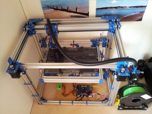
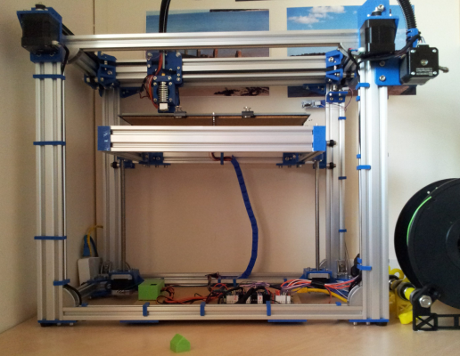
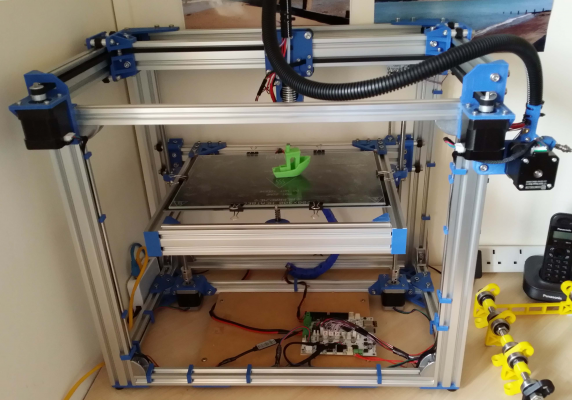
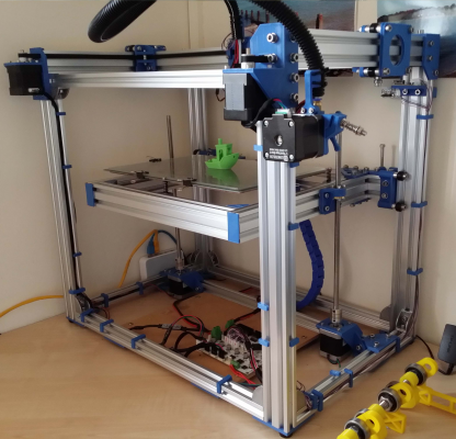
Well I have finished the basics and my D-Bot clone is up and running.
I have added metal corner brackets to help stiffen the frame.
I am using 2 nema17's with integrated lead screws, wired in series. This seems to be working well although they are getting extremely hot.
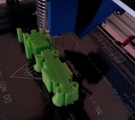
At the moment I am printing an elephant and have a large number of retractions and Z movement per layer, which I think is the reason for the hot Z motors at 49 C. I have the current set at 900 mA, I wonder if I should reduce it.
I have calibrated the steps per mm for the extruder and the XY and Z movements and am pleased with the accuracy.
I am very happy with the quality of the prints I am getting and am so pleased that I choose the D-Bot design which has belts running in the frame groves with no crossover or twists. The bed is very stable and I changed the design to be 3 point levelling. At the moment I have only had to level once, during commissioning so again am pleased with the stability and stiffness of the design.
I think I have a small filament cooling problem which I aim to address by designing a split fan airflow so both side of the nozzle have some cooling.
I have some lighting to fit and need to design a mount for my diamond hotend and the extra extruders.
here are some pictures of the machine in operation.
appjaws - Core XYUV Duet Ethernet Duex5
firmware 3.1.1 Web Interface 3.1.1
Ormerod 1-converted to laser engraver, Duet wifi
OpenSCAD version 2020.07
slic3r-1.3.0, Simplify3D 4.1.2, Cura-4.4.1
|
Re: appjaws-D-Bot progress June 13, 2016 01:41PM |
Registered: 8 years ago Posts: 12 |
|
Re: appjaws-D-Bot progress June 15, 2016 02:58AM |
Registered: 9 years ago Posts: 125 |
|
Re: appjaws-D-Bot progress July 05, 2016 07:31AM |
Registered: 10 years ago Posts: 780 |
Just thought I would update on my progress.
I originally bought 2 stepper motors with lead screws fitted, from reprap.me. These failed very quickly(after approx 6-8 hours printing) and now just make grinding noise and instead of turning they just vibrate. Reprap.me have been very unhelpful and are saying that the guarantee is only for 3 months, I requested replacement items or a refund and they are not willing to do anything to resolve problems caused by poor quality items and have shown complete disregard to the needs of their customers. I DO NOT RECOMMEND reprap.me for any purchases.
I have now obtain new steppers and 1 start lead screws which are working well.
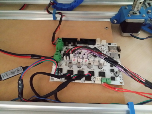
I have also fitted the new duet wifi control board, what a great piece of kit it is, no hard network connections needed, control of the printer via a web browser on my smart phone or computer is perfect.
Here are the latest pictures.
appjaws - Core XYUV Duet Ethernet Duex5
firmware 3.1.1 Web Interface 3.1.1
Ormerod 1-converted to laser engraver, Duet wifi
OpenSCAD version 2020.07
slic3r-1.3.0, Simplify3D 4.1.2, Cura-4.4.1
|
Re: appjaws-D-Bot progress July 05, 2016 05:47PM |
Registered: 8 years ago Posts: 88 |
I don't understand reprap.me issue. First, I think the warranty should be 2 years in EU. Second, why paying almost 2x the price when you can get the same "warranty" from aliexpress much cheaper?
When I buy stuff locally (in RO or EU) I do it for the warranty, or the chance to touch it and play with it (linear rails/guides for example).
When I buy stuff locally (in RO or EU) I do it for the warranty, or the chance to touch it and play with it (linear rails/guides for example).
|
Re: appjaws-D-Bot progress July 07, 2016 08:00PM |
Registered: 8 years ago Posts: 601 |
Is there too much friction being placed on the Z motors? It's possible that if the motors are not true to the frame, then the screws are trying to bend to that angle, putting stress on the motors. This may be why they are running hot. Also, if they are not levelled, then this will cause the same problem. One of your pictures above shows the bed is angled slightly.
This problem may also be that your delrin wheels are not taking the load of the bed, transferring alot of weight onto the lead screws, this will also cause the motors to overheat. They may need tightening, or metal mounts (the plastic mounts are likely to already be misshapen in a cantilevered bed).
If you use a flexible coupling, many of these issues may be solved. It will allow a screw that is not perfectly straight to rotate easier, without placing stress on the motor.
|
Re: appjaws-D-Bot progress July 08, 2016 07:35AM |
Registered: 9 years ago Posts: 125 |
Are stepper motors even affected by the load?
To my understanding they're being normally run on constant current regardless if they're moving or not, loaded or not, so the amount of load should not affect them at all, the stepper nor the driver is not affected by it.
Edited 1 time(s). Last edit at 07/08/2016 07:35AM by Mikk36.
To my understanding they're being normally run on constant current regardless if they're moving or not, loaded or not, so the amount of load should not affect them at all, the stepper nor the driver is not affected by it.
Edited 1 time(s). Last edit at 07/08/2016 07:35AM by Mikk36.
|
Re: appjaws-D-Bot progress July 08, 2016 09:07AM |
Registered: 11 years ago Posts: 5,780 |
It looks like the Z axis screws are quite far away from their guides. That's going to cause the mechanism to bind (or at least to increase the load on the motor) because the screws will be tilting the bed and undercarriage.
Ultra MegaMax Dominator 3D printer: [drmrehorst.blogspot.com]
Ultra MegaMax Dominator 3D printer: [drmrehorst.blogspot.com]
|
Re: appjaws-D-Bot progress July 11, 2016 11:35AM |
Registered: 10 years ago Posts: 780 |
|
Re: appjaws-D-Bot progress July 11, 2016 03:22PM |
Registered: 7 years ago Posts: 5 |
Quote
appjaws1
rethinking the Z setup, looking for ideas.
I released the Dbot mod/design/remix.
You added an extra rail to the front of your bed which is probably making it front heavy, the dimensions for the placement of the Z motors assume only two side bed rails so that the whole z platform is lifted from the center of gravity or very close to it.
You either need to remove that front rail or move your Z motors forward to properly lift the Z platform from the center of gravity.
My printer has hundreds of hours on it with the default Dbot setup and it works very well with no binding or motor problems.
|
Re: appjaws-D-Bot progress July 13, 2016 06:33AM |
Registered: 10 years ago Posts: 780 |
Thank you for your advice spauda01
I am so pleased with your design, thank you for your efforts. Which design software did you use to produce the components?
The reason I have a front rail is so that I can use 3 point bed levelling instead of the default 4 point. You are right I do need to move the motors near to the centre of gravity.
Do you find that the 2 motors go out of sync at all?
I have a small problem that perhaps you could help with. I am using a 300 x 200 mm bed heater which measures 317 x 213 mm with glass on top measuring 300 x 200 mm. The glass is held in position by the standard fold back clips which because they are so small just hold on to the edge of the glass, any small knock results in the clip jumping off the glass. I am using your Part cooling fan duct which hits the clips when printing close to the glass edge.
How do you overcome this problem?
appjaws - Core XYUV Duet Ethernet Duex5
firmware 3.1.1 Web Interface 3.1.1
Ormerod 1-converted to laser engraver, Duet wifi
OpenSCAD version 2020.07
slic3r-1.3.0, Simplify3D 4.1.2, Cura-4.4.1
Sorry, only registered users may post in this forum.
