My coreXY design is progressing to the build stage
Posted by the_digital_dentist
|
Re: My coreXY design is progressing to the build stage May 20, 2016 08:10AM |
Registered: 11 years ago Posts: 5,780 |
I have a couple milling machines available at the makerspace, so making slots is pretty easy. I don't know if I have a bit that is small enough, but I can always buy one.
Ultra MegaMax Dominator 3D printer: [drmrehorst.blogspot.com]
Ultra MegaMax Dominator 3D printer: [drmrehorst.blogspot.com]
|
Re: My coreXY design is progressing to the build stage May 20, 2016 10:08PM |
Registered: 11 years ago Posts: 1,049 |
Yes a mill is way to go.
NEMA 17 is M3 bolt 1/8 inch mill would be good
I suppose you will be milling a slot in aluminum.
A Dremel mill bit might be small enough
you could also use a Dremel stand to mill the slots
very slowly, small depth cuts
220-01 WorkStation
[www.dremel.com]

NEMA 17 is M3 bolt 1/8 inch mill would be good
I suppose you will be milling a slot in aluminum.
A Dremel mill bit might be small enough
you could also use a Dremel stand to mill the slots
very slowly, small depth cuts
220-01 WorkStation
[www.dremel.com]

|
Re: My coreXY design is progressing to the build stage May 30, 2016 06:51AM |
Registered: 9 years ago Posts: 1,873 |
Quote
DD
GT2 belt is 1.38 mm thick. When you interdigitate the teeth by folding the belt, the thickness becomes 2.2 mm. The clamp has 2.2 mm slots that don't allow the belt teeth any room to slide over each other.
Hi Mark, I used your approach, complete with measurements, to make cable clamps for my new Y axis carrier. Works a treat - many thanks!
|
Re: My coreXY design is progressing to the build stage May 30, 2016 09:32AM |
Registered: 11 years ago Posts: 5,780 |
Quote
JamesK
Quote
DD
GT2 belt is 1.38 mm thick. When you interdigitate the teeth by folding the belt, the thickness becomes 2.2 mm. The clamp has 2.2 mm slots that don't allow the belt teeth any room to slide over each other.
Hi Mark, I used your approach, complete with measurements, to make cable clamps for my new Y axis carrier. Works a treat - many thanks!
Like that guy on the interwebs said, "pictures or it didn't happen!"
Ultra MegaMax Dominator 3D printer: [drmrehorst.blogspot.com]
|
Re: My coreXY design is progressing to the build stage May 30, 2016 09:34AM |
Registered: 9 years ago Posts: 1,035 |
Quote
the_digital_dentist
Quote
JamesK
Quote
DD
GT2 belt is 1.38 mm thick. When you interdigitate the teeth by folding the belt, the thickness becomes 2.2 mm. The clamp has 2.2 mm slots that don't allow the belt teeth any room to slide over each other.
Hi Mark, I used your approach, complete with measurements, to make cable clamps for my new Y axis carrier. Works a treat - many thanks!
Like that guy on the interwebs said, "pictures or it didn't happen!"
Glad you asked that, it was painful to refrain to say that myself

RepRap Lander concept on Concept Forge
RepRap Lander concept on RepRap Forums
My Things, mostly experimental stuff
|
Re: My coreXY design is progressing to the build stage May 30, 2016 07:39PM |
Registered: 9 years ago Posts: 1,873 |
Ah, well this is embarrassing - my print quality is pretty horrible on these.
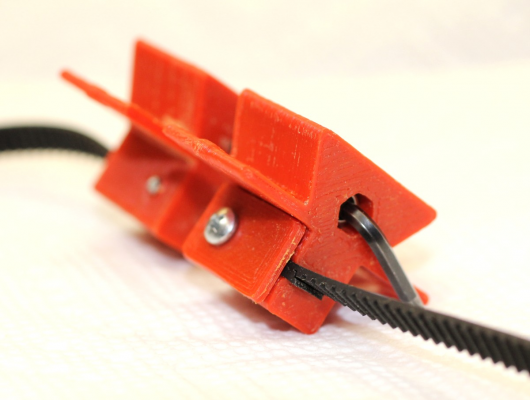
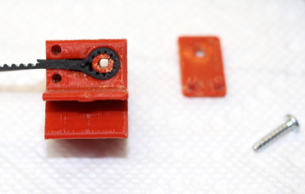
The clamps have a dovetail up top to fit into the bed carrier, and the belt clamp below with a simple cap screwed on to keep the belt in the recess. One of the clamps will be fixed to the carrier with screws through holes in the 'wings'. The other will be connected to the first by a screw through the hole that currently has a hex key in it to line the two pieces up for the photo, allowing tension adjustment.
The other side of the dovetail is in the centre part of the carrier/frog. Not sure if this print is going to work - it's pushing things a bit. The hope is that the new carrier will support an aluminium heat bed with piezo sensors on three point mounts.
Not shown are the two sides of the carrier that bolt to the sc8uu bearing blocks and have the mounts for the bed. The central part above doesn't carry any weight, it just has to transmit the Y axis movement to the bed mounts.
|
Re: My coreXY design is progressing to the build stage May 31, 2016 12:16AM |
Registered: 11 years ago Posts: 5,780 |
I like the way you're doing the tension adjustment. I may steal that from you.
I previously avoided trying to adjust belt tension at the clamps because of the difficulty of getting a tool in to make the adjustment because the tool has to be parallel and close to the belt. But, since the tension isn't something that has to be adjusted more than a few times in the life of the machine, why not?
Ultra MegaMax Dominator 3D printer: [drmrehorst.blogspot.com]
|
Re: My coreXY design is progressing to the build stage May 31, 2016 04:06AM |
Registered: 9 years ago Posts: 1,035 |
I have previously designed for a vertical X carriage a tensioner that needed a screwdriver be rotated in between belts and it felt unnatural so this time, for the horizontal x carriage I am designing, I will adopt front accessible bolts with dome_nuts to push the belt in a recess in the carriage:
But then again I have room to do this as the belt-catchers are not interfering with the printable X as they go into the YCarriages while the base part (green) goes until it touches the YCarriage.
Your twist-cancelling belt-catchers could extend a bit to allow a recess and a dome-nut+bolt to push the belt into that recess thus tensioning the belt...
Edited 1 time(s). Last edit at 05/31/2016 04:07AM by realthor.
RepRap Lander concept on Concept Forge
RepRap Lander concept on RepRap Forums
My Things, mostly experimental stuff
|
Re: My coreXY design is progressing to the build stage May 31, 2016 06:56AM |
Registered: 9 years ago Posts: 1,873 |
Quote
the_digital_dentist
I previously avoided trying to adjust belt tension at the clamps because of the difficulty of getting a tool in to make the adjustment because the tool has to be parallel and close to the belt. But, since the tension isn't something that has to be adjusted more than a few times in the life of the machine, why not?
I'm still not sure about it, adjustment is going to be fiddly for sure. It was largely a reaction to my first attempt which had the tensioning at the idler, but I made a very poor job of it and it has unwanted slop. I was thinking that putting the adjustment on the carriage would allow me to replace the idler with a simple fixed unit that could be small and tidy, but as well as the more difficult access it looks like the larger clamps on the carriage may restrict the travel. Didn't think that one all the way through!
Getting back to the original topic, have you decided what sort of Z mechanism you are going to use?
|
Re: My coreXY design is progressing to the build stage May 31, 2016 09:02AM |
Registered: 11 years ago Posts: 5,780 |
I'm leaning toward two screws driven by one motor and two linear guides.
Ultra MegaMax Dominator 3D printer: [drmrehorst.blogspot.com]
Ultra MegaMax Dominator 3D printer: [drmrehorst.blogspot.com]
|
New belt clamp design June 23, 2016 12:27PM |
Registered: 11 years ago Posts: 5,780 |
I've been finishing details of the design and will start cutting aluminum for the XY stage this weekend.
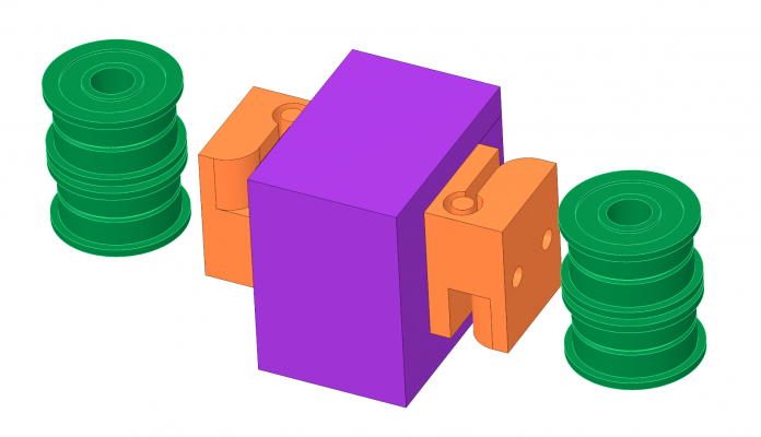
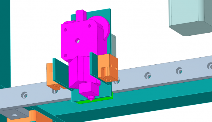
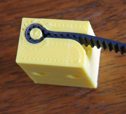
I reexamined my previous design and came up with some improvements, including a new self-locking, easily printable, single piece belt clamp design. I'm using stacked F608ZZ bearings (green) for pulleys with 9 mm wide GT2 belt. The belt clamps (orange) attach to the extruder carriage (purple). The width of the clamps matches the diameter of the bearings so the belts will be parallel to the X axis guide rail. Belts will be tensioned by sliding the motor mounts.
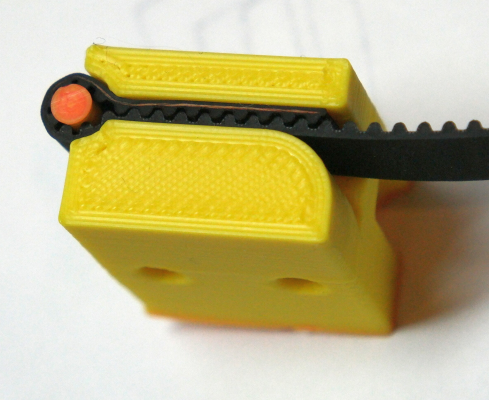
Here's a prototype:
And here's the final design:
I had previously hung the extruder from a relatively long piece of 2" tubing, but after trying several different configurations, I came up with this:
In this layout, the extruder nozzle is very close to the bearing block. This way, any slop in the bearing block will not be amplified by the long mount used in the previous design. The only potential problem with the new design is the air flow around the hot-end heatsink. I'm willing to take a chance on that working out OK.
Ultra MegaMax Dominator 3D printer: [drmrehorst.blogspot.com]
|
Re: My coreXY design is progressing to the build stage June 23, 2016 03:05PM |
Registered: 11 years ago Posts: 1,049 |
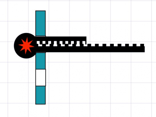
Perhaps KISS
A couple of slots in your extruder bracket
to trap the belt --- the red pin to keep loop in belt
could also put clamp over bitter end
frees up bracket space blocking coolong

A couple of slots in your extruder bracket
to trap the belt --- the red pin to keep loop in belt
could also put clamp over bitter end
frees up bracket space blocking coolong

|
Re: My coreXY design is progressing to the build stage June 23, 2016 08:12PM |
Registered: 11 years ago Posts: 5,780 |
I thought of that, and if I had a 2.2 mm end mill (actually several of them) I might try, but I don't, so I'd have to cut the slots all the way from the top edge down with a saw. I'm afraid that will make the piece a little too flexible. I could start with larger slots (for which I do have end mills) and print pieces with 2.2 mm slots to fit inside them, but I don't think that's a lot better than what I've already got. I don't have a lot of room for parts inside the bracket. As I've designed the XY mechanism, the belt clamps won't reduce the X axis motion at all.
Edited 1 time(s). Last edit at 06/23/2016 08:15PM by the_digital_dentist.
Ultra MegaMax Dominator 3D printer: [drmrehorst.blogspot.com]
Edited 1 time(s). Last edit at 06/23/2016 08:15PM by the_digital_dentist.
Ultra MegaMax Dominator 3D printer: [drmrehorst.blogspot.com]
|
Re: My coreXY design is progressing to the build stage June 23, 2016 10:14PM |
Registered: 13 years ago Posts: 268 |
|
Re: My coreXY design is progressing to the build stage June 25, 2016 07:52AM |
Registered: 8 years ago Posts: 3,525 |
I can highly recommend some type of x carriage with balanced belt tensioning. It makes calibration virtually non existent. Realtor and I messed about with some carriages that do this which I tested and it works as long as the belts are exactly the same length. I can also recommend steel reinforced belts, the belt runs on corexy's are long. I noticed an improvement in resolution with the steel reinforced belts.
Plus a lightweight design is the right way to go, these things are meant to be fast which necessitates lightweight construction. Its halfway between a delta and a cartesian. Too heavy and its not going to go any faster, so might as use a cartesian machine. My corexy prints well at 175mm/s. I posted some info in the smartrap forum.
I've thought about mounting a titan with pancake stepper to the x carriage and decided that going from 85g flex3drive to 250g titan plus 20mm nema 17 is too much mass added.
Just my twopence worth, looking forward to see what you come up with.
Simon Khoury
Co-founder of [www.precisionpiezo.co.uk] Accurate, repeatable, versatile Z-Probes
Published:Inventions
|
Re: My coreXY design is progressing to the build stage June 25, 2016 03:39PM |
Registered: 11 years ago Posts: 5,780 |
New clamp printed. Works perfectly.
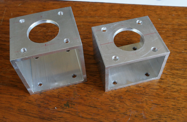
Motor mounts for XY stage:
Moving on to other things... X axis limit switch is next....
Edited 1 time(s). Last edit at 06/25/2016 03:42PM by the_digital_dentist.
Ultra MegaMax Dominator 3D printer: [drmrehorst.blogspot.com]
Motor mounts for XY stage:
Moving on to other things... X axis limit switch is next....
Edited 1 time(s). Last edit at 06/25/2016 03:42PM by the_digital_dentist.
Ultra MegaMax Dominator 3D printer: [drmrehorst.blogspot.com]
|
Re: My coreXY design is progressing to the build stage July 07, 2016 12:44AM |
Registered: 11 years ago Posts: 5,780 |
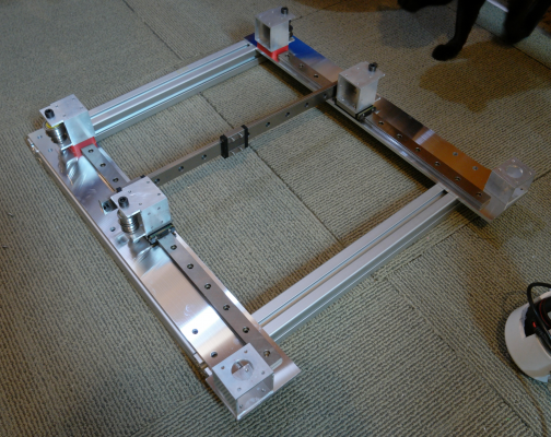
I spent the whole day in the machine shop at the makerspace and got a most of the XY mechanism finished. I still have to cut the linear guides to final lengths, then print some limit switch mounts and attach them, and finally test it. Motors should arrive in a few days.
I managed to mill the slots to slide the motor mounts without breaking the tool, so I'm pretty happy with the way it turned out.
The frame is 40 mm square T-slot extrusion milled square and to exact lengths and the Y axis linear guides are mounted in 1/4" MIC6 tooling plate. The bed plate will be 305 x 305 mm, Z axis and remainder of frame are yet to be designed, but it will be completely enclosed and heated. I am planning on a minimum of 600 mm print height, with the bed lifted by 2 or 3 lead screws. The bed heater will be line powered and the rest of it will run on 24V, assuming I can adequate performance from the motors without resorting to DSP drivers.
Ultra MegaMax Dominator 3D printer: [drmrehorst.blogspot.com]
|
Re: My coreXY design is progressing to the build stage July 07, 2016 01:36AM |
Registered: 7 years ago Posts: 168 |
|
Re: My coreXY design is progressing to the build stage July 07, 2016 04:35AM |
Registered: 10 years ago Posts: 221 |
|
Re: My coreXY design is progressing to the build stage July 07, 2016 08:21AM |
Registered: 11 years ago Posts: 5,780 |
Quote
hobbymods
Why did you use T slot extrusion when you're mounting the linears on flat plate?
I trust the tooling plate to be flatter than the T slot extrusion, I intend to enclose the printer, I don't quite trust the 1/4" tooling plate alone not to sag over the span (I suppose I could have used 1/2" plate), and I couldn't figure out an easy way to cut the whole plate from a single piece of tooling plate.
Most coreXY designs mount the linear guides directly on the top of the frame members and typically the bearing blocks and/or stuff attached to them extends beyond the sides of the frame. Both situations create problems for enclosing the machine. My XY (and Z) mechanism will be contained entirely within the frame (with the motors extending outside the frame) making enclosure as easy as adding flat top and side panels. I'll probably use the magnetic strips and polycarbonate panels I used in my other printer. It is easy to see what's going on in the machine, extremely easy to access the mechanism if necessary (which is actually pretty rare), and they seal the enclosure almost air-tight. The footprint of this machine is pretty large compared to the bed plate area, but that's what happens when you build it to be enclosed.
Quote
RodF
Moving mass low, stationary mass high. That will work. Naturally I am interested in the level of accuracy you can achieve on the XY plane.
Moving mass isn't particularly low- I estimate about 1.5 kg all-in but I think I'll be able to push it around with NEMA-17 motors and keep the noise level down. My other machine is a bit noisy and my wife complained about it so much that I took it to the makerspace and left it there about 4 months ago (to the delight of the members at the makerspace). I want this one to be quiet enough to keep and use at home.
I am using 400 step/rev motors which gives a calculated step size of 6.5 um/ustep at 16:1 microstepping. I'm trying to keep everything rigid so that I have some hope of actually achieving that resolution, but I'm not 100% sure the motor torque will be adequate to print at at least 50 mm/sec. The 400 step/rev NEMA-17 motors have limited torque compared to the 200 step/rev motors that are available, and I was not able to locate a torque vs speed curve, so I picked motors that were similarly spec'd to one where I did find a speed vs torque curve. The calculations I did on the Oriental Motor site involved a lot of assumptions, and I tried to stay conservative, but we'll see once the motors arrive and I get everything set up. If I have to I can switch over to 200 step/rev NEMA-17 motors or 400 step/rev NEMA-23 motors and get higher torque.
It also remains to be seen how much belt stretch and slop in the mechanism contributes to errors. I mounted the X axis guide rail using a bearing block to allow for thermal expansion of the XY stage (the Y axis rails move apart when heated). That may allow some undesired motion, too. We'll see. The biggest drawback to the coreXY mechanism is the belt length. If it proves to be unsatisfactory, I can always convert the mechanism to a plain Cartesion system using shorter belts.
Edited 1 time(s). Last edit at 07/07/2016 09:37PM by the_digital_dentist.
Ultra MegaMax Dominator 3D printer: [drmrehorst.blogspot.com]
|
Re: My coreXY design is progressing to the build stage July 15, 2016 06:14AM |
Registered: 8 years ago Posts: 346 |
|
Re: My coreXY design is progressing to the build stage July 15, 2016 07:14AM |
Registered: 10 years ago Posts: 14,672 |
Quote
the_digital_dentist
Moving mass isn't particularly low- I estimate about 1.5 kg all-in but I think I'll be able to push it around with NEMA-17 motors and keep the noise level down. My other machine is a bit noisy and my wife complained about it so much that I took it to the makerspace and left it there about 4 months ago (to the delight of the members at the makerspace). I want this one to be quiet enough to keep and use at home.
If you really want it to be quiet, use a Duet WiFi to control it, or something else with high microstepping. The 256x microstepping drivers on the Duet WiFi give a huge reduction in the noise level compared to x16 microstepping drivers. The noisiest components on my delta are now the fans and the non-toothed idler pulleys. EDIT: see [www.duet3d.com] for what other people think.
Quote
the_digital_dentist
I am using 400 step/rev motors which gives a calculated step size of 6.5 um/ustep at 16:1 microstepping. I'm trying to keep everything rigid so that I have some hope of actually achieving that resolution, but I'm not 100% sure the motor torque will be adequate to print at at least 50 mm/sec. The 400 step/rev NEMA-17 motors have limited torque compared to the 200 step/rev motors that are available, and I was not able to locate a torque vs speed curve, so I picked motors that were similarly spec'd to one where I did find a speed vs torque curve. The calculations I did on the Oriental Motor site involved a lot of assumptions, and I tried to stay conservative, but we'll see once the motors arrive and I get everything set up. If I have to I can switch over to 200 step/rev NEMA-17 motors or 400 step/rev NEMA-23 motors and get higher torque.
As I said in another post, torque vs. speed curves are only relevant when using constant voltage drive, which we don't use in 3D printers. With constant current drive, the point at which the torque drops off depends on the drive voltage. 400 step motors have twice the back emf due to rotation that 200 step motors do at the same speed, so they need higher drive voltage to achieve the same speeds. My delta manages 400mm/sec travel speed using 400 step 1.68A Nema 17 motors and 24V power and also has a resolution of 0.625um, so if you use 24V power then I think you should have no trouble achieving 50mm/sec in spite of the much larger mass of your print head compared to mine.
You may find Ryan Carlyle's stepper simulator spreadsheet useful, see [groups.google.com].
Edited 3 time(s). Last edit at 07/15/2016 07:30AM by dc42.
Large delta printer [miscsolutions.wordpress.com], E3D tool changer, Robotdigg SCARA printer, Crane Quad and Ormerod
Disclosure: I design Duet electronics and work on RepRapFirmware, [duet3d.com].
|
Re: My coreXY design is progressing to the build stage July 15, 2016 07:30AM |
Registered: 11 years ago Posts: 5,780 |
No, crossing the belts is only necessary if you keep everything at the same vertical level. I am separating the belts vertically so they don't cross. I am also not twisting the belts at all and using relatively large diameter smooth pulleys made from flanged ball bearings.
If you must have the smallest possible vertical size, crossing/twisting the belts will help. If you stack the belts vertically, the main problem is keeping the pulley axles vertical. If you try to simply stand the pulleys up on a bolt with only one end anchored, keeping the bolt vertical can be hard to do because of the tension on the belts. I fixed that by using 2" square aluminum tubing to mount the pulleys so the pulley axles are supported at top and bottom.
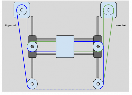
This is the belt layout (someone else's drawing), but I made a small modification when I built the mechanism.
The X axis is horizontal and Y axis is vertical. Notice that the X axis is shown at about the middle of Y axis range of motion. Now imagine it moved downward to the far end of the Y axis range (that would put the X axis at the bottom of the drawing). The distance between the portion of the upper belt (blue) that rides on the corner pulley (lower left) and the X axis pulley becomes very small. I didn't like the clearance- the belt teeth were facing each other and if the belt wobbled at all while moving I thought it was possible for the teeth to engage and cause all sorts of problems. I increased the spacing by using larger diameter corner pulleys. You can see the belt path on one side of the mechanism in this picture:
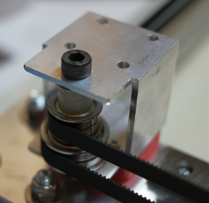
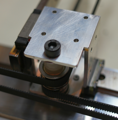
and detail of the bearings at both ends of the X axis and the Y axis corners here:
The smaller pulleys are F608ZZ bearings and the larger pulleys are F6903ZZ bearings. The F608ZZ have an 8mm bore, so I used 8 mm bolts to hold them with 1.5 mm thick nylon washers stacked to space the pulleys vertically and fit them into the 2" square aluminum tube brackets. The F6903ZZ bearings have a 17 mm bore so I printed bushings to reduce that to 8mm and printed a tapered washer to use as a spacer between the F6903ZZ and the F608ZZ bearings.
Edited 1 time(s). Last edit at 07/15/2016 07:47AM by the_digital_dentist.
Ultra MegaMax Dominator 3D printer: [drmrehorst.blogspot.com]
|
Re: My coreXY design is progressing to the build stage July 15, 2016 08:26AM |
Registered: 10 years ago Posts: 221 |
|
Re: My coreXY design is progressing to the build stage July 16, 2016 08:59AM |
Registered: 11 years ago Posts: 5,780 |
Thanks. It all seems very rigid. The bearing brackets can actually be made using just a saw and a drill press, but I had a milling machine available so I milled everything.
The way I have built the assembly, the belt tension puts side loading on the Y axis bearing blocks. Not ideal, but the load is very small compared to the rated load for these things (we have a milling machine at the makerspace that uses the same size linear guides to move the head!) so I'm not too concerned about it. I may yet revisit the design and move the X axis pulley to the X axis rail on the side that attaches to the extra X axis bearing block. That would take the side load off the Y axis blocks and put it on the X axis rail (I'm not sure if that's better).
In the end I may end up rigidly connecting the two Y axis blocks together with an aluminum tube, similar to my other printer.
Ultra MegaMax Dominator 3D printer: [drmrehorst.blogspot.com]
|
Re: My coreXY design is progressing to the build stage July 17, 2016 09:56AM |
Registered: 7 years ago Posts: 109 |
|
Re: My coreXY design is progressing to the build stage July 17, 2016 07:39PM |
Registered: 11 years ago Posts: 5,780 |
The extra bearing block on the X axis is there because the machine will be heated to print ABS. That heat causes the Y axis rails to move farther apart which, without the extra bearing block on the X axis, will put a very large side load on the Y axis bearing blocks, possibly causing the mechanism to bind.
That said, the belt tension is already putting some side load on the Y axis bearing blocks. I am looking into a design change to eliminate that.
Ultra MegaMax Dominator 3D printer: [drmrehorst.blogspot.com]
That said, the belt tension is already putting some side load on the Y axis bearing blocks. I am looking into a design change to eliminate that.
Ultra MegaMax Dominator 3D printer: [drmrehorst.blogspot.com]
|
Re: My coreXY design is progressing to the build stage July 17, 2016 11:15PM |
Registered: 7 years ago Posts: 168 |
Quote
the_digital_dentist
The extra bearing block on the X axis is there because the machine will be heated to print ABS. That heat causes the Y axis rails to move farther apart which, without the extra bearing block on the X axis, will put a very large side load on the Y axis bearing blocks, possibly causing the mechanism to bind.
That said, the belt tension is already putting some side load on the Y axis bearing blocks. I am looking into a design change to eliminate that.
I've agonized over the effects of thermal expansion myself, but there's not much info on its effect on linear rails out there.
I ran it past Hiwin Australia, and also past a couple of CNC machining workshops.
All said "it should be OK", which didn't really satisfy me.
When I pressed Hiwin further they came back with this: [www.engineeringtoolbox.com]
They said that they'd worked out over 400-500mm the difference in expansion between the precision rail and the aluminium plate would be something like 4 microns per 15-20 degC which was acceptable.
It still worries me, but I thought that if I assembled/aligned/torqued the rails at say 24-26 degC (airconned room temp), I should be fine with cold starts at 10degC through to 50degC enclosure temps.
My X carriage will be made of the same ally that the mount surface for the Y rails use, and while both will have precision rails bolted to them, the rails will not be bolted directly to each other.
Still worrying about it......
|
Re: My coreXY design is progressing to the build stage July 18, 2016 06:56AM |
Registered: 7 years ago Posts: 109 |
That's why I am designing my printer to keep the frame cool but the inside of the printing chamber warm. I'm going to try the Stratasys method with the bellows right under the X axis and the walls will be within the frame. So practically, all the supporting structures will be outside the heated chamber.
|
Re: My coreXY design is progressing to the build stage July 18, 2016 10:33AM |
Registered: 11 years ago Posts: 5,780 |
I think the frame of my enclosed machine will probably be a bit cooler than the interior air temperature because of the mass of the aluminum in the frame and the exposure of the frame to outside air, depending on how I actually enclose the machine. Over a period of several hours the frame parts may get close to the 50C of the interior air space. For maximum print quality it may be best to preheat the machine for an hour or so to get everything up to stable temperatures.
I don't think the heat will have much effect on the rails and bearing blocks except to soften the lubricants a bit. Since the guides are all steel there won't be a lot of thermal expansion taking place. The main concern is with the Y axis rails moving apart as the aluminum pieces that separate them heat up. Additional concerns about steel rails screwed to aluminum frame members or plates- the differential expansion will cause the assembly to bow a little unless the screws slide a bit (we're talking just a few microns at each screw). Will everything remain aligned after multiple heat/cool cycles?
My current printer has a linear guide in the X axis that is screwed to a piece of rectangular aluminum tubing. It performs extremely well and has been doing so for about 2 years of almost daily ABS printing, so maybe all this concern over thermal expansion is overblown.
Ultra MegaMax Dominator 3D printer: [drmrehorst.blogspot.com]
Sorry, only registered users may post in this forum.
