My coreXY design is progressing to the build stage
Posted by the_digital_dentist
|
Re: My coreXY design is progressing to the build stage August 08, 2016 05:09AM |
Registered: 10 years ago Posts: 38 |
Digital Dentist
I have been following your Core XY build and have been inspired to build one of my own when I have time.
If you do not mind I have a few questions. Having been through this thread a couple of times I have been unable to find the answers.
First, you mention using 24mm by 8mm linear rails. Where did you purchase these? If they are something that you got second hand, would an acceptable substitute be found on the Alibaba web site?
Second, you are using a 9mm wide timing belt. What is the pitch the belts.
Lastly, The pulleys that are mounted to your steppers. How many teeth do they have.
Your help is appreciated. Thank You.
Edited 1 time(s). Last edit at 08/08/2016 05:10AM by Kasahabo.
|
Re: My coreXY design is progressing to the build stage August 08, 2016 08:37AM |
Registered: 11 years ago Posts: 5,780 |
Quote
Kasahabo
First, you mention using 24mm by 8mm linear rails. Where did you purchase these? If they are something that you got second hand, would an acceptable substitute be found on the Alibaba web site?
I bought them used, via ebay. The X axis rail is actually unused old stock and came from someone in the US for $35. The Y axis rails are used and came from a dealer in Korea- the pair was $75 including shipping. Deals like that come up on ebay all the time, in between the hundreds of over priced offers, just be patient. You can use almost any linear guides that you have on hand or can get for a reasonable price- the rails I used are definitely overkill. We have a milling machine at the makerspace that uses the same sized rails for Z axis motion of the head. I've heard mixed reviews of the HiWin rails- some swear by them, others seems to get them missing balls, etc. Maybe it depends on the source... The used rails are almost always missing a few balls which won't affect their operation, just maximum load.
Quote
Kasahabo
Second, you are using a 9mm wide timing belt. What is the pitch the belts. Lastly, The pulleys that are mounted to your steppers. How many teeth do they have.
GT2 timing belt- 2 mm pitch. I got it from Folgertech, along with the 20 tooth motor pulleys.
I used F608zz bearings for most of the pulleys and F6903zz bearings for the the two larger pulleys. The larger pulleys are used at the corners of the frame opposite the motors and help prevent belt interference. The pulleys are mounted in 2" square aluminum tubing and I used stacked nylon washers, 1.5mm thick, as spacers. For the larger pulleys I printed bushings to reduce their bore from 17 mm to 8 mm, and I used M8 bolts for the pulley axles. The stacked bearings provide an 11 mm wide space for the belt.
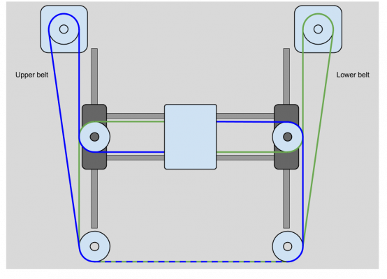
This is the belt/pulley/motor layout, except that I used larger pulleys in the corners opposite the motors:
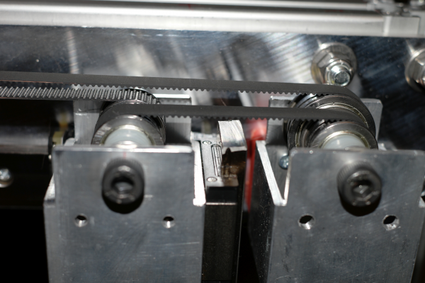
Here is a picture of one end of the X and Y axes showing the two different sized pulleys. The belt exiting on the left side goes directly to the "A" motor. The pulleys on the left are on one end of the X axis, those on the right are part of the Y axis. The large pulley prevents potential belt interference by separating the two sides of the belt. If I had used the same 22 mm pulley for that, the belt might have interfered with itself at this end of the Y axis. The larger pulley guarantees 4 mm minimum clearance. I used the 2" square tubing to try to keep the pulley axles perpendicular to the XY plane- if you just screw them into a plate, they will tend to flex inward as the belt tension pulls on them.
The extruder carriage belt clamp is printed- you can DL the files here: [www.youmagine.com]
The two key points to note about the belt clamp are that the slot for the folded belt is 2.2 mm wide which fits the folded belt but doesn't allow it to slip, and the width of the clamp exactly matches the diameter of the pulleys at either end of the X axis (F608zz: 22 mm). The vertical spacing of the belt slots, each 11 mm tall to match the pulleys, matches the vertical spacing of the pulleys, too. With that info it should be very easy to redesign for any size pulleys and any belt width you decide to use.
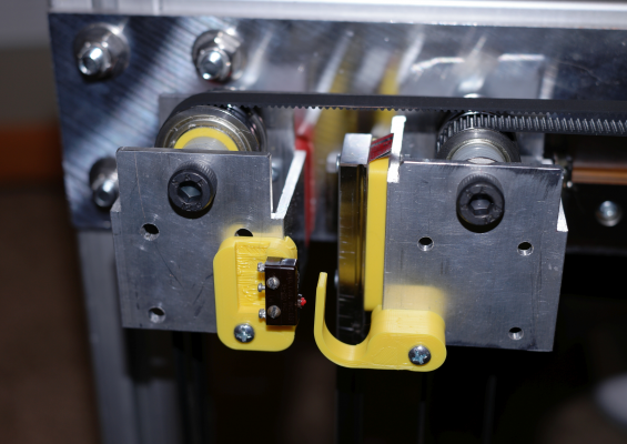
I used a standard microswitch for the Y axis home position limit switch. There's no adjustability- none really needed here. I have an industrial optical switch that I'll be using for the X axis limit switch that will allow both ends of the switch, the source and receiver, to be mounted on the XY frame without adding any wires to the extruder carriage. It will detect the X=0 no matter where the X axis is positioned along the Y axis. Here is the Y axis limit switch. The pulleys on the right side of the picture are on the end of the X axis. The belt that exits to the right of the photo goes to the "B" motor. The pulleys on the left are the fixed Y axis pulleys with the larger one on top (F6903zz) blocking the view of the smaller one on the bottom. You can see the printed bushing (yellow) and the stacked nylon washers used to space the bearings in their mounts.
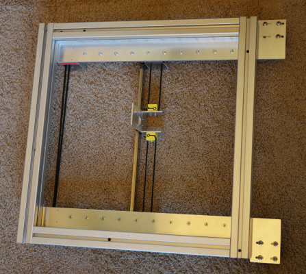
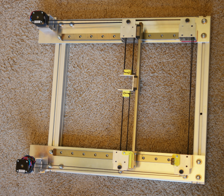
The frame for this assembly is made from 40 mm square T slot extrusion (purchased from a local scrap yard for $2/lb), 530 x 530 mm, and 1/4" cast tooling plate (cutoff purchased from Howard precision Metals for $2.50/lb). I cut the frame pieces on a band saw then milled them square and to matching lengths. I tapped the axial holes and bolted them together. The tooling plate was cut, then milled, and drilled on the milling machine. I used a machinist's square to align the edges of the plates with the frame, and bolted them down using 5/16" carriage bolts, then aligned one of the Y axis rails parallel to the edge of the plate and screwed it down tightly. I used a metal spacer to set the other rail parallel to the first and screwed it down. Motion is very smooth and consistent at all positions along both the X and Y axes. The X and Y axes are orthogonal according to my machinist's square, but I'll run some tests when I have it hooked to a controller.
I mounted a couple of 400 step/rev motors that I calculate to have adequate torque, but they look awfully small to me. I haven't tested it with a controller yet, so we'll see. The motor mounts were made from 2" square and 1.5"x2" aluminum tubing and mount on slots in the base plates to allow belt tension adjustment (see a previous post). This assembly weighs about 8.5 kg and is rock solid.
I am currently redesigning the extruder carriage and may have the new version finished later this week.
Edited 3 time(s). Last edit at 08/08/2016 10:28AM by the_digital_dentist.
Ultra MegaMax Dominator 3D printer: [drmrehorst.blogspot.com]
|
Re: My coreXY design is progressing to the build stage August 09, 2016 05:44AM |
Registered: 10 years ago Posts: 38 |
Thank you for taking time to further explain some of the finer details of your build. I have to agree with your build philosophy as you have described in the documentation of your Son of Megamax Build. Being a machinist I have higher expectations of 3d printers than some. I have seen comments in forums where one person is trying to achieve unreasonable tolerances from their machine and others respond by saying that the part should be machined. I think that is not the point. The challenge for me is doing ones best to reach those unreasonable goals.
|
Re: My coreXY design is progressing to the build stage August 09, 2016 12:45PM |
Registered: 11 years ago Posts: 5,780 |
I connected one motor to a driver and sent it some signals from an arduino board and it had no problem moving the mechanism along at about 100 mm/sec. It's quite surprising how powerful these little motors can be. I'll try to hook it to a proper printer controller next...
Ultra MegaMax Dominator 3D printer: [drmrehorst.blogspot.com]
Ultra MegaMax Dominator 3D printer: [drmrehorst.blogspot.com]
|
Re: My coreXY design is progressing to the build stage August 09, 2016 02:47PM |
Registered: 8 years ago Posts: 153 |
One thing you'll want to be aware of, is that the corex/y algorithm approximately doubles the resolution of your steppers, so your 100mm/s move is actually 50mm/s in corexy space. I think 1.8 degree steppers would be fine if you find the speed is too limited with 0.9.
Edited 1 time(s). Last edit at 08/09/2016 02:50PM by n8bot.
Edited 1 time(s). Last edit at 08/09/2016 02:50PM by n8bot.
|
Re: My coreXY design is progressing to the build stage August 09, 2016 03:41PM |
Registered: 8 years ago Posts: 70 |
|
Re: My coreXY design is progressing to the build stage August 10, 2016 12:11AM |
Registered: 11 years ago Posts: 5,780 |
Quote
n8bot
One thing you'll want to be aware of, is that the corex/y algorithm approximately doubles the resolution of your steppers, so your 100mm/s move is actually 50mm/s in corexy space. I think 1.8 degree steppers would be fine if you find the speed is too limited with 0.9.
If a single motor turns, you get motion in both axes, moving the extruder along a 45 degree line. Each axis moves by 1/2 the belt motion, so the net motion is sqrt (2)/2 * belt motion. If one motor moves the belt 40 mm (20 tooth pulley, 2 mm pitch, one rev), X and Y each move 20 mm and the extruder carriage moves 28.284 mm along the 45 degree line. Speed should translate the same way. If the belt moves 40 mm/sec, the extruder will move 28.284 mm/sec.
If both motors turn so the extruder carriage moves only in X or Y, the motion of each belt is the same as the motion of the extruder carriage. If both A and B belts move 40 mm in the same direction, the extruder moves 40 mm along the X axis. If they move equally in opposite directions, the extruder moves along the Y axis.
I assume the firmware calculates the extruder carriage speed so it can match the plastic extrusion speed to it and not over or under extrude.
So the worst case resolution occurs at maximum speed, when extruder carriage motion is in only one axis or the other. Assuming 20 tooth drive pulleys, if the motor makes 200 steps per rev, each full step will move the carriage 0.2 mm. A 400 step per rev motor will deliver 0.1 mm/full step. Those values divide by whatever microstepping ratio is used.
Ultra MegaMax Dominator 3D printer: [drmrehorst.blogspot.com]
|
Re: My coreXY design is progressing to the build stage August 11, 2016 01:58PM |
Registered: 8 years ago Posts: 153 |
Yeah, I'm not saying there is any problem with it (and it gets quite confusing for me quickly, which is why I'm designing a cartesian not a corexy  ), I was just pointing out that being able to move the 0.9 at "100mm/s" in real space, it will equate to a slower actual feedrate when printing. Just something to be aware of. It was one of the things I considered when thinking about the corexy solution: 1.8 degree steppers could be sufficient resolution, due to the way corexy increases the resolution.
 ), I was just pointing out that being able to move the 0.9 at "100mm/s" in real space, it will equate to a slower actual feedrate when printing. Just something to be aware of. It was one of the things I considered when thinking about the corexy solution: 1.8 degree steppers could be sufficient resolution, due to the way corexy increases the resolution.
|
Re: My coreXY design is progressing to the build stage August 11, 2016 02:00PM |
Registered: 8 years ago Posts: 3,525 |
I use 1.8 deg steppers but 16t pulleys and can print reliably at 175mm/s.
Simon Khoury
Co-founder of [www.precisionpiezo.co.uk] Accurate, repeatable, versatile Z-Probes
Published:Inventions
Simon Khoury
Co-founder of [www.precisionpiezo.co.uk] Accurate, repeatable, versatile Z-Probes
Published:Inventions
|
Re: My coreXY design is progressing to the build stage August 13, 2016 05:09PM |
Registered: 11 years ago Posts: 5,780 |
First test of the mechanism- some circles that are supposed to be running at 100, 200, and 400 mm/sec, though the third one doesn't seem to be going that fast to me. I'm looking into that issue now. The mechanism is connected to a Smoothieboard controller, running on 12V.
CoreXY test
I sliced a file of an object I had previously designed to see how it would handle a more real-world situation. I also connected to a 24V power supply that will be installed in the machine when it is complete. I played around with more speed/acceleration tests a little, but most of that will have to wait until the rest of the machine is ready. It seems the tiny motors have sufficient torque for the sort of print speeds I want (100 mm/sec max). I set the motor current to 2A. After about 2 hours of running, the motors are about 5C above the room temperature.
I made a half-assed attempt to put a pencil on the extruder carriage, but the lead broke almost immediately. I will print a pen holder tomorrow and mount it and try some drawings. The pen will be mounted on a linear guide that will let the pen move vertically but have zero lateral play.
More video
Still more video
This is getting redundant
Edited 2 time(s). Last edit at 08/13/2016 09:45PM by the_digital_dentist.
Ultra MegaMax Dominator 3D printer: [drmrehorst.blogspot.com]
|
Re: My coreXY design is progressing to the build stage August 14, 2016 11:22PM |
Registered: 11 years ago Posts: 5,780 |
Today I added a pen mount to the extruder carriage and used the CoreXY mechanism as a draw-bot. It was "printing" a part I designed and printed a couple months ago at 100 mm/sec. There appears to be some shifting in the Y axis, so I'll probably have to turn down the speed and/or acceleration and junction deviation a little.
More video here: [vimeo.com] and [vimeo.com]
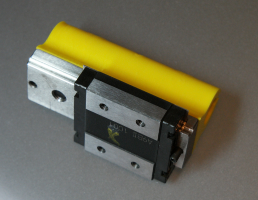
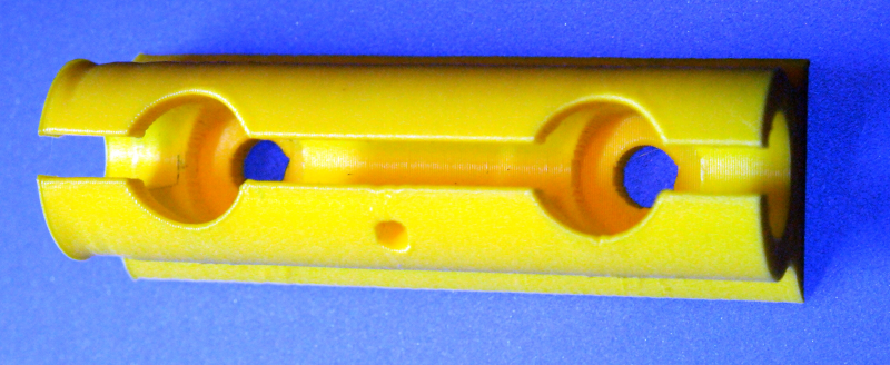
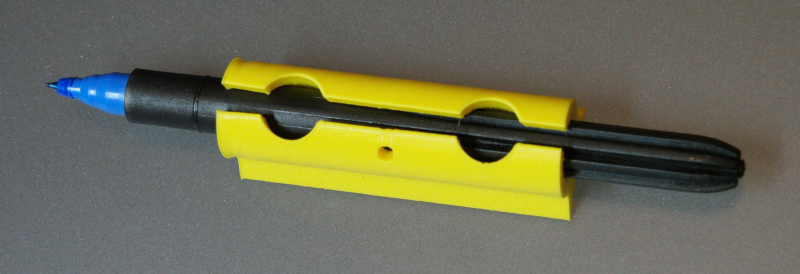
The pen holder consists of a short linear guide with bearing block screwed to the extruder carriage and a 3D printed pen mount screwed to the guide rail. The pen can move vertically in case the mechanism isn't level or the printing surface is uneven. but it can't move laterally because the linear guide won't let it. The weight of the guide rail and pen keep the pen against the printing surface- it's pretty hard on a dry erase marker tip because it's a little heavy. I'm going to try mounting a stylus and have it draw spirograph patterns in sand, and just keep overwriting them as it goes.
Ultra MegaMax Dominator 3D printer: [drmrehorst.blogspot.com]
|
Re: My coreXY design is progressing to the build stage August 16, 2016 05:20PM |
Registered: 7 years ago Posts: 168 |
Fully agree with supporting the pulley axles top and bottom.
Are you using precision shoulder bolts there?
I was trying to go with them, but have found that 5mm linear rod is cheaper and can be cut to length which made it much simpler.
Have you considered coming up from below with the steppers?
I'm going to mount mine underneath and make some kind of bearing/housing to hold extended shafts coupled onto the stepper shaft. Once I've got it all right I might even order steppers with longer shafts to eliminate the coupler.
Edited 1 time(s). Last edit at 08/16/2016 06:06PM by hobbymods.
|
Re: My coreXY design is progressing to the build stage August 16, 2016 05:54PM |
Registered: 8 years ago Posts: 153 |
|
Re: My coreXY design is progressing to the build stage August 17, 2016 01:19AM |
Registered: 11 years ago Posts: 5,780 |
Quote
hobbymods
Fully agree with supporting the pulley axles top and bottom.
Are you using precision shoulder bolts there?
These are the bolts I used:[www.ebay.com]
They had about 50mm of unthreaded shaft, and then I cut them to the length I needed. I destroyed a band saw blade in the process because I didn't realize the bolts were hardened.
The portion that goes through the bearings is unthreaded, but the bearings fit over them easily. The spacers that jam the bearings between the top and bottom of the square tube prevent wobbling.
Quote
hobbymods
Have you considered coming up from below with the steppers?
I'm going to mount mine underneath and make some kind of bearing/housing to hold extended shafts coupled onto the stepper shaft. Once I've got it all right I might even order steppers with longer shafts to eliminate the coupler.
That sounds like a lot of trouble to go through - it's a lot easier to just mount the motors where the belts are. Is there some reason you need to come up from the bottom? One of my motor mounts is tall- made from 2" square tubing - for the upper belt, and the other is shorter- made from 1.5" x 2" tubing. Since the pulleys are about 11 mm wide, the 1/2" (12.7 mm) difference in motor height is just about perfect for mounting the motor pulleys at the same heights as the other pulleys. The mechanism ends up being a little taller, but the motors are mounted outside the enclosure in my machine so the extra height that they contribute doesn't affect anything else. The frame of my printer will extend well above the XY mechanism and its motors.
The corexy assembly will be mounted in the printer with the motors, guide rails, pulleys, and belts all facing down.
Edited 1 time(s). Last edit at 08/17/2016 01:23AM by the_digital_dentist.
Ultra MegaMax Dominator 3D printer: [drmrehorst.blogspot.com]
|
Re: My coreXY design is progressing to the build stage August 17, 2016 03:52AM |
Registered: 7 years ago Posts: 168 |
DD,
I actually do have a bit of a reason for the stepper location.
It will allow me to put them out in the fresh air with the way my design is.
I'm looking to put just my XYZ steppers out of the build chamber, as I'll have that set at 50 degC controlled max temps at times.
Never had a problem with steppers on other machines getting that hot in enclosures, but am thinking it will be a nice touch given the big jobs and heavy running gear in this design.
|
Re: My coreXY design is progressing to the build stage August 24, 2016 12:26PM |
Registered: 10 years ago Posts: 651 |
DD,
I've got a couple of questions. My XY stage is shaping up to be pretty similar to yours (after modeling multiple variations, it really seems best).
Having the X rail anchored on one end and floating through a bearing block, when it comes to tensioning the belts, I would think that having one end of the X rail floating would allow the entire idler assemblies to tilt inward towards the carriage. I know the point of CoreXY is that the forces cancel out at the carriage, but it seems there's still an inward pull at the idlers. Which would be negated in most designs as the rails are not allowed to float. I'm wondering if you're seeing any kind of tilt in your idler assemblies, not so much in the bearings cause I know you've got them supported on top and bottom, but rather the entire assembly including the bearing block.
My second question also has to do with belt tensioning. With your carriage in the U shape it is, when belts are tensioned, have you seen the U spread at all? Wondering if a bolt through it would be beneficial to prevent it from spreading.
|
Re: My coreXY design is progressing to the build stage August 24, 2016 01:23PM |
Registered: 11 years ago Posts: 5,780 |
Belt forces: having the X axis rail float in a bearing block allows the assembly to expand as it heats up without putting large lateral forces on the Y axis guides/bearing blocks. It also prevents the inward forces on the X axis pulleys from trying to bow the X axis guide rail. The price to pay is the side force that the belt tension produces on the Y axis guide rails/blocks, but that force is only a tiny fraction of the rated load for even small linear guides.
The pulleys can't really tilt inward because of the tube supports that are firmly anchored to the Y axis bearing blocks.
There are two alternatives- mount the X axis pulleys on the X axis rail which will eliminate the side loading on the Y axis blocks but increase the forces trying to bow the X axis rail, or use the conventional method and fix the ends of the X axis rail to the Y axis bearing blocks, which then leads to large side loads on the Y axis rails/blocks when the machine expands as it heats up for ABS printing.
The X axis rail can flex slightly under the belt tension forces that vary dynamically, which means the two Y blocks can potentially get "out of sync" allowing the X axis to tilt slightly relative to the Y axis. I will know if it is a problem when I actually try printing with this set-up. One nice thing about building the XY mechanism as a separate module is that I will be able to pull it from the machine and make changes easily. If I need to fix the Y axis blocks to the ends of the X axis rail because of print quality problems, I will do it, as long as the whole thing still works over the temperature range I need- about 15C-50C.
Yes, the walls of the carriage are pulling outward under the belt tension - a redesign is in the works. I will leave the now-open side closed except for a hole for hot-end cooling - I'll mount a fan on the front surface of the carriage and use a printed duct to steer the air flow over the heatsink. I may also add metal plates on the outer surfaces of the belt clamps to help stiffen them- time, heat and belt tension will eventually cause the ABS to distort.
Edited 1 time(s). Last edit at 08/24/2016 01:29PM by the_digital_dentist.
Ultra MegaMax Dominator 3D printer: [drmrehorst.blogspot.com]
|
Re: My coreXY design is progressing to the build stage September 25, 2016 10:39PM |
Registered: 11 years ago Posts: 5,780 |
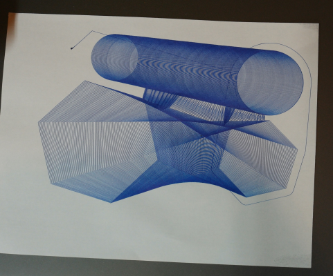
I was at the Milwaukee Maker Faire this weekend and took my CoreXY mechanism along. On Saturday I didn't have it connected to anything, but on Sunday I decided to hook it up to a controller and put a pen on the extruder carriage. After watching it try to replicate solid infill and almost wear a hole through the paper I came up with an idea for something that would keep it printing for a long time without going over previously drawn stuff over and over. I created a couple simple parts- a tilted cone and a tilted hexagonal solid that expanded and rotated as it went up. I used the spiral vase settings in slic3r and set bottom layers to "0" when I sliced. Wow! It makes a super high precision drawbot. I gave the drawings away to kiddies who were asking for them, but I'll run a couple more and post images here.
I specifically drew tilted objects but I'm going to try using the layer change g-code tab in Slic3r to shift the layers slightly in X and/or Y, then slice with 0 bottom layers and spiral vase mode turned on. That should allow any STL file to produce interesting drawings.
Something else occurred to me. I have been planning to build the CoreXY machine's Z axis with as much as 1 m of travel. The problem, of course, is that the machine would be very tall and a little difficult to transport to places like the Maker Faire. That got me thinking that since the coreXY mechanism is modular, I could build two different assemblies, one with a short and one with a long Z axis and then move the coreXY module between them. If the controller board goes with the coreXY mechanism, the Z axis assemblies would only require connection of the Z axis motor and maybe the Z axis limit switch(es) to the controller. Hmmmm.
Edited 1 time(s). Last edit at 09/25/2016 11:01PM by the_digital_dentist.
Ultra MegaMax Dominator 3D printer: [drmrehorst.blogspot.com]
|
Re: My coreXY design is progressing to the build stage September 26, 2016 02:52PM |
Registered: 9 years ago Posts: 251 |
Quote
the_digital_dentist
Something else occurred to me. I have been planning to build the CoreXY machine's Z axis with as much as 1 m of travel. The problem, of course, is that the machine would be very tall and a little difficult to transport to places like the Maker Faire. That got me thinking that since the coreXY mechanism is modular, I could build two different assemblies, one with a short and one with a long Z axis and then move the coreXY module between them. If the controller board goes with the coreXY mechanism, the Z axis assemblies would only require connection of the Z axis motor and maybe the Z axis limit switch(es) to the controller. Hmmmm.
Awesome idea!
You could really be on to something here... Looking at my Fusebox and and I could easily move the mechanism to a larger frame without any big issues. Could easily sell kits for the mechanism, then offer different size bodies for people who want a machine for small or large prints.
Edited 1 time(s). Last edit at 09/27/2016 10:20AM by widespreaddeadhead.
|
Re: My coreXY design is progressing to the build stage October 01, 2016 10:53AM |
Registered: 11 years ago Posts: 5,780 |
Here is a pen holder that I can screw to the extruder carriage. I printed a friction fit holder for a Koh-i-noor art-pen and screwed it to a short linear guide rail. The bearing block screws to the extruder carriage. The weight of the pen and rail provide the downward force, and the pen is free to move up and down if the mechanism isn't level with the plane of the paper.
Video of it running here: [vimeo.com]
The result:
Ultra MegaMax Dominator 3D printer: [drmrehorst.blogspot.com]
Video of it running here: [vimeo.com]
The result:
Ultra MegaMax Dominator 3D printer: [drmrehorst.blogspot.com]
|
Re: My coreXY design is progressing to the build stage October 01, 2016 11:08AM |
Registered: 9 years ago Posts: 1,873 |
That's really neat.
I've been thinking about how to use the salvaged rails I was given, and I decided to give coreXY a try. So, no surprise I've been reading through this thread to get some guidance. One thing I noticed was you mentioned cutting the rails to fit. Given the high value of the rails, I was wondering why you didn't adjust the design to match the rails, rather than the other way around?
Edited 1 time(s). Last edit at 10/01/2016 11:08AM by JamesK.
|
Re: My coreXY design is progressing to the build stage October 02, 2016 08:47PM |
Registered: 11 years ago Posts: 5,780 |
I buy the rails second-hand via ebay. They aren't all that expensive or valuable.
I had some design goals for the size of the machine in mind so I cut the rails as needed. The Z axis, OTOH, is still up in the air. I'm considering making two different Z axis assemblies into which I can drop this mechanism, one shorter for easy transport, the other longer to enable taller prints.
I'm also looking at using the mechanism as a plotter/drawbot with the addition of a simple frame and maybe an electrostatic paper hold-down.
Ultra MegaMax Dominator 3D printer: [drmrehorst.blogspot.com]
|
Re: My coreXY design is progressing to the build stage October 05, 2016 05:53PM |
Registered: 11 years ago Posts: 156 |
|
Re: My coreXY design is progressing to the build stage October 12, 2016 05:30PM |
Registered: 7 years ago Posts: 1 |
.... and your girlfriend can dance on the music it makes
Nice setup and inspiration too. Hope one day i will make my own. But there are so many variables. Probably i start simpel and buy a Prusa.
Can't wait till you show the Z axes. Btw which 0.9 motors did you choose (and will you choose the same for the Z-axe) and do you have a way tensioning the belts? On the video they look very straight.
|
Re: My coreXY design is progressing to the build stage October 12, 2016 06:54PM |
Registered: 11 years ago Posts: 5,780 |
The motors are 17HM19-2004S
I haven't designed the Z axis yet, but it's unlikely to use the same motor.
The belts are tensioned by moving the motor mounts- the base to which they are attached has slots for the screws to allow the motor and mount to slide up to 10 mm.
Ultra MegaMax Dominator 3D printer: [drmrehorst.blogspot.com]
|
Re: My coreXY design is progressing to the build stage October 19, 2016 01:20PM |
Registered: 11 years ago Posts: 5,780 |
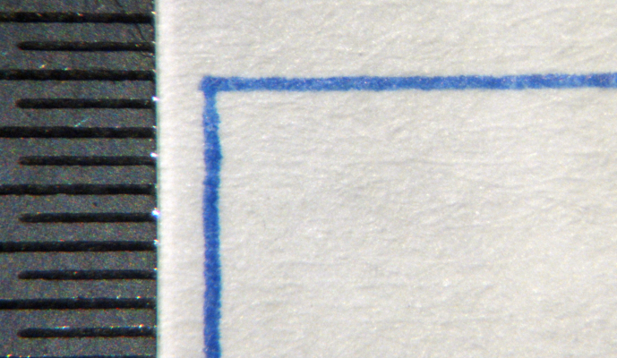
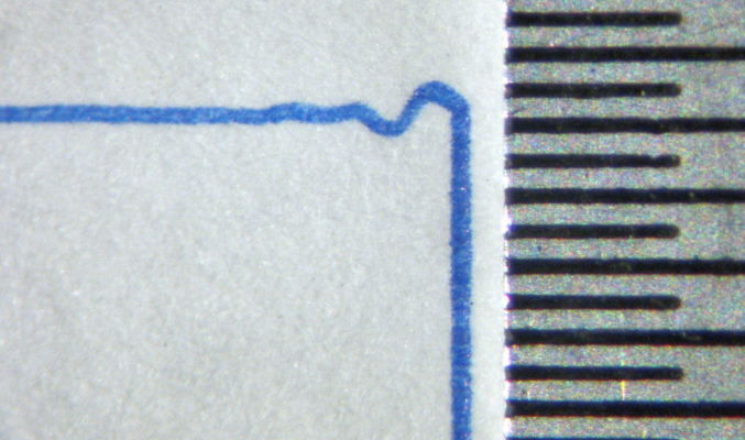
I decided that while I was messing with a pen on the mechanism, I may as well use it to see if the axes are square and how well they behave. I had it draw a 200 x200 mm square at 100 mm/sec, acceleration set to 2000 mm/sec^2, junction deviation 0.5 mm, then I measured the diagonals to check for squareness (and used a protractor) and found that as well as I am able to measure, the axes are square. I did see something interesting in the lines, so I made a couple pictures with a microscope.
Here is one corner of the square where the pen was moving right to left along the X axis and then turned and moved downward along the Y axis. Divisions on the scale are 0.5 mm, and the diagonally opposite corner is almost identical to this one:
Here is the adjacent corner where the pen was moving upward along the Y axis, then turned and moved to the left on the X axis. The diagonally opposite corner is almost identical:
The extra mass in the Y axis is obviously a bit harder for the motors/controller to keep under control. The ripple in the drawing would show up in 3D prints as ringing on those corners. I need to play with acceleration, junction deviation, and speed a bit to minimize the ripple.
Update: I tweaked the acceleration down to 1500 mm/sec^2, junction deviation down to 0.1 mm, and reduced motor currents to 1.6A. I have run multiple tests, including single motor (45 degree lines) up to 400 mm/sec and it seems to work fine. Yes, it actually hit 400 mm/sec as I was printing lines that were 250 mm long. The reduced current has made it run a little quieter. I am currently running from a 12V supply, but will be running from 24V when the machine is finished.
Edited 3 time(s). Last edit at 10/20/2016 12:25AM by the_digital_dentist.
Ultra MegaMax Dominator 3D printer: [drmrehorst.blogspot.com]
|
Re: My coreXY design is progressing to the build stage October 20, 2016 12:12AM |
Registered: 8 years ago Posts: 916 |
|
Re: My coreXY design is progressing to the build stage November 07, 2016 05:09PM |
Registered: 8 years ago Posts: 1,671 |
|
Re: My coreXY design is progressing to the build stage November 07, 2016 05:54PM |
Registered: 11 years ago Posts: 5,780 |
I don't know the exact value, and I won't be home for a couple days to measure it. The travel on each is about the same - around 320 mm in X and Y.
I'm planning on using a Titan extruder and V6 hot-end, so I don't think the extruder mass will be a lot more than the pen holder and pen (the linear guide and bearing block probably weigh as much as the motor I'll use for the extruder).
Ultra MegaMax Dominator 3D printer: [drmrehorst.blogspot.com]
I'm planning on using a Titan extruder and V6 hot-end, so I don't think the extruder mass will be a lot more than the pen holder and pen (the linear guide and bearing block probably weigh as much as the motor I'll use for the extruder).
Ultra MegaMax Dominator 3D printer: [drmrehorst.blogspot.com]
|
Re: My coreXY design is progressing to the build stage November 07, 2016 07:14PM |
Registered: 8 years ago Posts: 1,671 |
No worries, when u have time, I just remember you removing the arm of the other one, so would be good to compare the difference,
my linear rails 330mm(usable travel a little less maybe 300mm) but I have a back plate for it and other bits to go on, trying to find my scales so I can weigh mine to compare.
Hoping its not too heavy for use in the core, but its perfect for my other design.
Edited 1 time(s). Last edit at 11/07/2016 07:58PM by MechaBits.
Sorry, only registered users may post in this forum.
