My coreXY design is progressing to the build stage
Posted by the_digital_dentist
|
Re: My coreXY design is progressing to the build stage November 14, 2016 03:29PM |
Registered: 11 years ago Posts: 5,780 |
I just ordered a pair of 760 mm long linear guides for the Z axis. The build envelope for my CoreXY machine will be 300 x 300 x 700 mm. Now working on the final decision on moving the bed up and down- possibly belts...
Ultra MegaMax Dominator 3D printer: [drmrehorst.blogspot.com]
Ultra MegaMax Dominator 3D printer: [drmrehorst.blogspot.com]
|
Re: My coreXY design is progressing to the build stage November 15, 2016 02:45PM |
Registered: 11 years ago Posts: 225 |
Hi,
As a owner of both F8 screw on a "heavy" Z axis/bed and a "lighter" bed with belt on a Tantillus if I can give advice:
Belt pro:
- No more wobble.
- Fast speed homing, Z retract
- Less noise
- Easier to design.
Belt con:
- Bed go down when power off stepper.
- lower resolution
- Torque more important needed.
|
Re: My coreXY design is progressing to the build stage November 15, 2016 02:58PM |
Registered: 8 years ago Posts: 3,525 |
Yeah I also run belts for a z axis on a corexy, and I'd say I agree with all the pros. As for the cons yes it does free fall on power off but a command to move to max position after printing finishes (or home if using max endstop) works well, plus a long stepper deactivation delay and some landing gear in the form of springs or something similar. I have a counterweight also which helps a lot. Lower resolution - yes theoretically but using 16 tooth pulleys and 0.9 deg steppers the resolution is potentially 5 microns, practically probably 10 but this ought to be sufficient.
I was very dubious until I built one, and was impressed with how well it worked. I wouldn't even contemplate the hassle of switching to leadscrews/ballscrews and synchronising them with belts/shafts etc..
Simon Khoury
Co-founder of [www.precisionpiezo.co.uk] Accurate, repeatable, versatile Z-Probes
Published:Inventions
|
Re: My coreXY design is progressing to the build stage November 18, 2016 06:15PM |
Registered: 11 years ago Posts: 5,780 |
The Z axis linear guides are in and they are perfect! THK HSR-15 rails with R-type blocks. 760 mm long. $124 for the pair, shipped from Texas. I bought guides from this company before and they have all been reasonably priced and performed perfectly. All three of these names show up in the listing: CDN Systems LLC, athomemarket, dougdeals
athomemarket seems to be an ebay store for CDN Systems LLC. DougDeals is in the graphics on the auction pages. Anyway, if you need quality, used linear guides, these people usually have some good deals.
Proceeding with Z axis design...
Ultra MegaMax Dominator 3D printer: [drmrehorst.blogspot.com]
athomemarket seems to be an ebay store for CDN Systems LLC. DougDeals is in the graphics on the auction pages. Anyway, if you need quality, used linear guides, these people usually have some good deals.
Proceeding with Z axis design...
Ultra MegaMax Dominator 3D printer: [drmrehorst.blogspot.com]
|
Re: My coreXY design is progressing to the build stage November 24, 2016 09:48AM |
Registered: 11 years ago Posts: 5,780 |
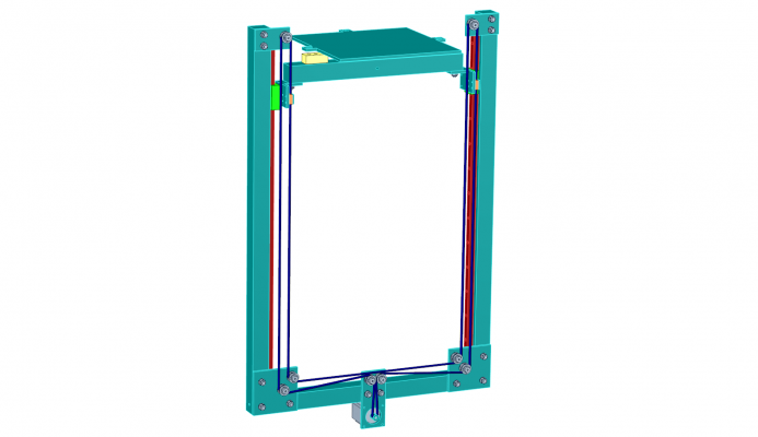
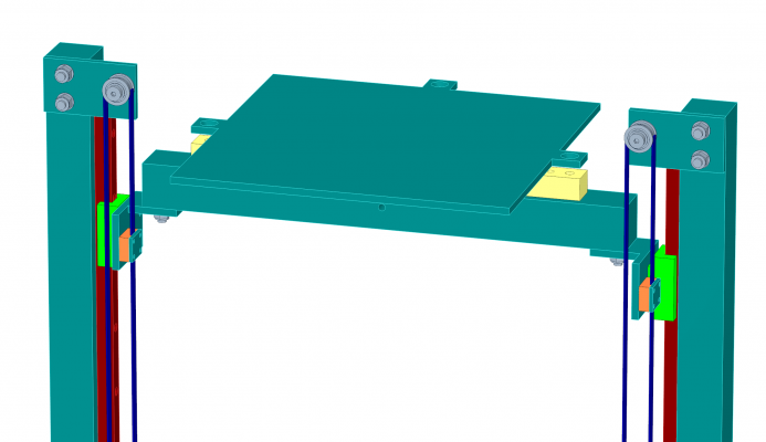
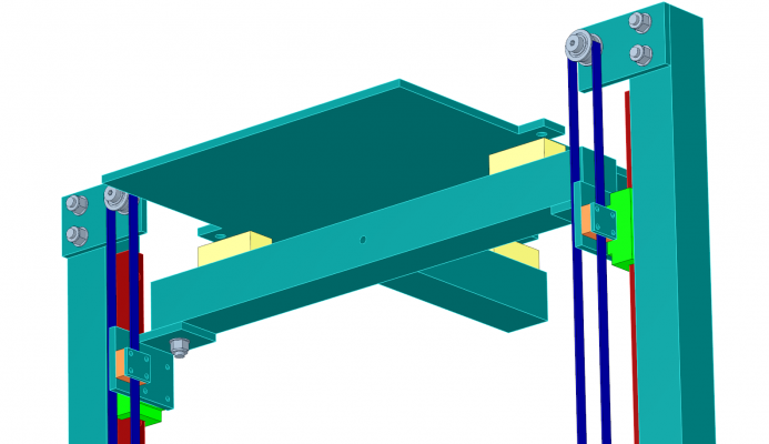
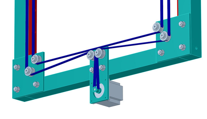
Almost finished with Z axis design. after seeing the results others have achieved, I decided to try belt drive. I have come up with several different configurations and found this one easiest to make work with the XY stage and easiest to fabricate. The frame for the Z axis, like the rest of the machine, will be made from 4040 t-slot extrusion. Printable volume will be 305 x 305 x 700 mm. Pulleys will be F608zz bearings mounted on 1/4" plate using shoulder screws. The belt will be 9 mm wide and will be tensioned by moving one or both of the top pulley plates. The bed plate will be lifted on two linear guides placed at the middle of the bed (yes, the bed is cantilevered off either side of the cross bar). Motive force will be provided by a 160 oz-in NEMA-23 motor that I have handy (maybe overkill on the torque, but the motor is variable reluctance type with no detent torque so it should be quite smooth running). The bed will be supported on three screws driven into teflon blocks (yellow) bolted to a 4040 tee that will be connected to the linear guides via 1/4" angle brackets. The pulley plates will attach to the frame using carriage bolts and will serve as hard endstops for the linear guides (I'll probably add some printed TPU bumpers). I'll be using line powered bed and enclosure heaters, both switched with SSRs and under control of the Smoothieboard. This frame will be bolted solidly into the printer's frame at top and bottom. The trickiest part will be aligning it, but I'll figure that out.
The bed plate has ears for the leveling screws so the full 305 x 305 area will be printable. I'll be putting 30 or 60 mil PEI on the bed plate (getting great results on SoM).
The orange pieces are printed belt clamps. That design may change to allow belt tension adjustment at the clamps- I may copy the design used for the Y axis belt clamps in my CubeX Duo and split one of the clamps into two sections to allow belt tension adjustment at the clamp.
The motor will have a 20 tooth pulley giving 80 steps per mm (12.5 um per ustep) Z axis capability. I'll probably use a 1 mm nozzle so that's going to be more than enough Z resolution.
Edited 2 time(s). Last edit at 11/24/2016 10:48AM by the_digital_dentist.
Ultra MegaMax Dominator 3D printer: [drmrehorst.blogspot.com]
|
Re: My coreXY design is progressing to the build stage November 24, 2016 10:24AM |
Registered: 9 years ago Posts: 1,873 |
I like the way you've got the centre-line of the bed over the Z axis carrier and guides, that looks like a very smart layout compared to the typical cantilever setup that puts a long arm between the bed CofG and the bearings.
Why are the belt idlers above the motor so high? It looks kind of odd with the lower belt pushed up like that, although I can't think of any negatives.
Why are the belt idlers above the motor so high? It looks kind of odd with the lower belt pushed up like that, although I can't think of any negatives.
|
Re: My coreXY design is progressing to the build stage November 24, 2016 10:44AM |
Registered: 11 years ago Posts: 5,780 |
I initially put the four pulleys (motor pulleys and corner pulleys) in line for convenience. I've already dropped them down a bit and moved the motor up a little, too. There will probably be many such refinements over the next few days.
I had to lift the bed above the bearing blocks to get it up to the extruder nozzle. I'm looking at changing the extruder carriage design to position the nozzle lower, which will solve some problems with the extruder mount and possibly allow the cross-bar of the tee to fit between the bearing blocks.
Edited 1 time(s). Last edit at 11/24/2016 10:47AM by the_digital_dentist.
Ultra MegaMax Dominator 3D printer: [drmrehorst.blogspot.com]
|
Re: My coreXY design is progressing to the build stage November 24, 2016 12:59PM |
Registered: 11 years ago Posts: 1,049 |
Teeter Totter
Are the trolleys on rails really that slop free (rotation on rail)?
Perhaps use two trolleys -- spaced out -- on each rail
Departure from your 3 or 4 point suspension?
Teflon blocks to make bed Teeter Totter better --- or thermal break?
Will you use brake on motor or just let bed fall 700mm?

Are the trolleys on rails really that slop free (rotation on rail)?
Perhaps use two trolleys -- spaced out -- on each rail
Departure from your 3 or 4 point suspension?
Teflon blocks to make bed Teeter Totter better --- or thermal break?
Will you use brake on motor or just let bed fall 700mm?

|
Re: My coreXY design is progressing to the build stage November 24, 2016 01:01PM |
Registered: 9 years ago Posts: 1,873 |
|
Re: My coreXY design is progressing to the build stage November 24, 2016 03:03PM |
Registered: 11 years ago Posts: 5,780 |
Quote
cozmicray
Teeter Totter
Are the trolleys on rails really that slop free (rotation on rail)?
Perhaps use two trolleys -- spaced out -- on each rail
Departure from your 3 or 4 point suspension?
Teflon blocks to make bed Teeter Totter better --- or thermal break?
Will you use brake on motor or just let bed fall 700mm?
1) Yes, linear guides have zero slop. That's what makes them so good! Try them some time- you'll never go back to end supported round rails. These bearing blocks have 4 rows of balls in contact with the rail. They move only in the direction of the guide rail, and do so very smoothly. Hi-Win guides are supposed to be good, but there are a lot cheapo knock-offs that people complain about. I prefer to buy Japanese/German/Swiss/US made stuff because I know it will be high quality. I suspect the 1/4" L brackets will flex and allow more movement than the bearing blocks. If I have problems with it, I'll add a third lifter.
2) Teflon for thermal break. Bed will be heated...
3) Let it fall. I'll put some TPU bumpers and/or springs at the bottom so it doesn't make a big noise or bang anything too hard. I'll look into adding a relay to short the motor windings when power is dead. The motor will act as a brake and it will fall slowly or not at all. I've been printing for 3+ years now and never had a print fail due to loss of power, so it's a low priority. I'll set the end g-code in the slicer to lower the bed at the end of a print before disabling the motors.
Edited 1 time(s). Last edit at 11/24/2016 03:06PM by the_digital_dentist.
Ultra MegaMax Dominator 3D printer: [drmrehorst.blogspot.com]
|
Re: My coreXY design is progressing to the build stage November 28, 2016 01:09AM |
Registered: 7 years ago Posts: 168 |
Just a quick question...
Why do you use F608Z flanged bearings instead of F606Z?
I use the 9mm wide belt as well, and looking at the specs the 606's would fit nicely with 0.6mm clearance on that belt.
I'm just wondering, as I'd prefer to use 6mm shoulder bolts to mount my idlers on than 8mm.
Is there a reason for your choice that gives an advantage over the 606?
Should there be more clearance between the edges of the belt and the inside of the flanges?
I was determined to use toothed idlers on the tooth side of the belts in my corexy design, but I've just given up on trying to find some.
I'm thinking twin F606Z's on 6mm unbrako shoulder bolts would gice a nice aligned result.
Cheers,
Edited 1 time(s). Last edit at 11/28/2016 01:25AM by hobbymods.
|
Re: My coreXY design is progressing to the build stage November 28, 2016 10:07AM |
Registered: 11 years ago Posts: 5,780 |
6 mm shoulder screws have either M4 (M5?) threads. I feel like that's getting pretty small to withstand the lateral force due to the belt tension without flexing/tilting. If each of those 8 screws flexes just a little, the belt is going to be riding on the outer flanges all the time. I have mixed feelings about using the M8 screws because they have M6 threads, but I'm going to give them a try and see if they work. If I don't like the way they behave, I'll drill out the holes and use M8 bolts. Then all I have to worry about is the 1/4" aluminum plate flexing.
The belt should ride on the central, flat part of the pulley and shouldn't be running against the flanges at all if it can be prevented. 0.6 mm clearance assumes the belt is pretty good quality. I've been using cheapo belt from Folger Tech and found that their slicing isn't very consistent so the width varies along the length of the belt. 0.6 mm clearance is cutting things a little too close for comfort . The motor pulleys for 9 mm belt are usually 11 mm wide and the F608zz bearings match that width.
The toothed idlers are nice, but you have to use shoulder screws with them (though most people probably don't) because they don't have spacers between the center rings of the bearings. The shoulder screws that fit them have to be pretty small to accommodate the bearings plus the additional size of the aluminum part of the pulley. I see many such pulleys for 6mm wide belt, but not many for 9mm wide belt. Maybe the greater load that is assumed with 9mm wide belt would be too much for the skinny shoulder screws, but a more likely explanation is that 9mm wide parts cost more so aren't as popular with the hobbyist 3D printing market. 3D printing hobbyists are usually cheapskates, and shoulder screws are pretty expensive as hardware goes, so you don't usually see them offered for sale with the 6mm pulleys.
Ultra MegaMax Dominator 3D printer: [drmrehorst.blogspot.com]
|
Re: My coreXY design is progressing to the build stage November 28, 2016 10:51AM |
Registered: 9 years ago Posts: 1,873 |
Quote
I have mixed feelings about using the M8 screws because they have M6 threads, but I'm going to give them a try and see if they work. If I don't like the way they behave, I'll drill out the holes and use M8 bolts.
The shoulder of the bolt should pass through the load bearing material on both sides of the pulley. The threaded section should only be preventing the bolt from withdrawing, not carrying any of the lateral load. An M8 shoulder bolt used properly can only be stronger in shear than an M8 thread of the same material.
|
Re: My coreXY design is progressing to the build stage November 28, 2016 11:45AM |
Registered: 11 years ago Posts: 5,780 |
That makes a lot of sense. I'll have to look at adding plates and spacers above the pulleys (like I did using rectangular tubing with the pulleys in the XY mechanism). Thanks.
Ultra MegaMax Dominator 3D printer: [drmrehorst.blogspot.com]
Ultra MegaMax Dominator 3D printer: [drmrehorst.blogspot.com]
|
Re: My coreXY design is progressing to the build stage November 28, 2016 03:50PM |
Registered: 7 years ago Posts: 168 |
Quote
the_digital_dentist
6 mm shoulder screws have either M4 (M5?) threads. I feel like that's getting pretty small to withstand the lateral force due to the belt tension without flexing/tilting. If each of those 8 screws flexes just a little, the belt is going to be riding on the outer flanges all the time. I have mixed feelings about using the M8 screws because they have M6 threads, but I'm going to give them a try and see if they work. If I don't like the way they behave, I'll drill out the holes and use M8 bolts. Then all I have to worry about is the 1/4" aluminum plate flexing.
The belt should ride on the central, flat part of the pulley and shouldn't be running against the flanges at all if it can be prevented. 0.6 mm clearance assumes the belt is pretty good quality. I've been using cheapo belt from Folger Tech and found that their slicing isn't very consistent so the width varies along the length of the belt. 0.6 mm clearance is cutting things a little too close for comfort . The motor pulleys for 9 mm belt are usually 11 mm wide and the F608zz bearings match that width.
The toothed idlers are nice, but you have to use shoulder screws with them (though most people probably don't) because they don't have spacers between the center rings of the bearings. The shoulder screws that fit them have to be pretty small to accommodate the bearings plus the additional size of the aluminum part of the pulley. I see many such pulleys for 6mm wide belt, but not many for 9mm wide belt. Maybe the greater load that is assumed with 9mm wide belt would be too much for the skinny shoulder screws, but a more likely explanation is that 9mm wide parts cost more so aren't as popular with the hobbyist 3D printing market. 3D printing hobbyists are usually cheapskates, and shoulder screws are pretty expensive as hardware goes, so you don't usually see them offered for sale with the 6mm pulleys.
Fair enough.
As someone else mentioned, I wouldn't be relying on the thread for load carrying, I'd have the shoulder section through a bracket above and below the pulley.
I agree with what you said regarding the width of the belt, and so now have both F606's and F608's coming....sigh....more bits for the "bits box", but I guess they'd work with a 6mm belt in some future silliness.
The cheap Chinese toothed idlers all come with a 5mm ID bearing, which is difficult but not impossible to find shoulder bolts for, but the bearings are absolute rubbish with 1 in 3 being notchy (IME).
I really wish I could find a matching set of both toothed and plain flanged idlers around the 30T size for 9mm GT2 belt, with decent 6mm ID bearings....does anyone know where to get them?
If it's a matching set I'd be prepared to spend a bit more.
|
Re: My coreXY design is progressing to the build stage November 29, 2016 10:20PM |
Registered: 8 years ago Posts: 916 |
Quote
cozmicray
Teeter Totter
Are the trolleys on rails really that slop free (rotation on rail)?
Perhaps use two trolleys -- spaced out -- on each rail
I agree, there's a lot of mechanical advantage for a long bed trying to twist a tiny little carriage. I know that my linear rail carriages have a minute, but appreciable, rotational slop. Multiply that by the length of the bed and you have quite a bit of vertical play at the edge of the bed. Commercial positioning systems always use at least two carriages per rail.
|
Re: My coreXY design is progressing to the build stage November 30, 2016 08:23AM |
Registered: 11 years ago Posts: 5,780 |
My experience with the linear guide in the X axis of my printer is zero detectable slop in any direction, but it doesn't have a 150 mm lever arm with which to multiply the error. In this CoreXY, there are no forces trying to twist the bed except flaws in the guide rail. It may be that as the bearings move up and down the rails, such flaws will tilt the bed back and forth. That's why the bed is as close to centered between the rails as I can make it. It's better to have the two sides of the bed bounce up and down 100 um than to have one side bounce 200 um like a fully cantilevered design.
Once I get the Z axis assembled I can clamp a laser to the bed and make measurements of the step to step distance with a ruler on a distant wall. The distance will act as a multiplier of the tilt and it should become pretty obvious if there are any issues, and easy to calculate the amount of tilt/wobble occuring. If this Z axis configuration doesn't work I can always switch to a three screw lifter, though there's no reason (right now) to believe it would be any better. In that case errors in the screws will cause the bed to wobble vertically as it moves. Right now I trust these bearings/rails to be more accurate than screws.
Ultra MegaMax Dominator 3D printer: [drmrehorst.blogspot.com]
|
Re: My coreXY design is progressing to the build stage December 11, 2016 11:29PM |
Registered: 11 years ago Posts: 5,780 |
The bottom part of the Z axis was fabricated today. I still need to bore out the center hole for the motor- that requires setting up a rotary table on the mill and I didn't have time for that today. I still have to mill the two vertical pieces to equal lengths. Meanwhile, the T-nuts to mount the linear guides are on a slow boat from China.
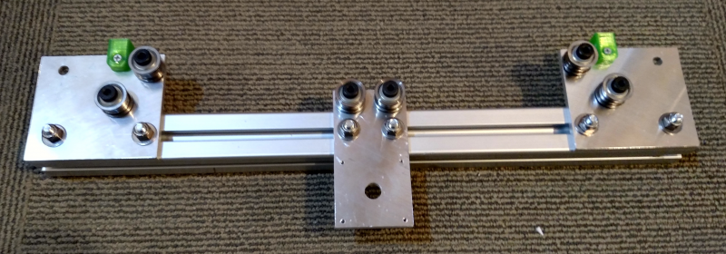
The green blocks are printed TPU bumpers so that it won't bang metal on metal when the power is cut off and the bed drops. There are similar bumpers on the bearing plates (also fabricated today) at the top of the Z axis. Each pulley consists of 2x F608zz bearings (to accommodate 9mm wide GT2 belt) mounted on shoulder bolts, currently using nylon washers as spacers but may replace them with steel. The pulleys and motor are mounted on 1/4" cast tooling plate, with 5/16" carriage bolts in the T slots and nylock nuts clamping everything tightly. The motor plate will hold a 164 oz-in NEMA-23 motor with a 20 tooth pulley.
I'll be picking up the .313" X 13.250" X 14.625" cast tooling plate bed plate on Wednesday (to be cut to 305 mm square with tabs for the leveling screws). Howard Precision Metals- $15!
Ultra MegaMax Dominator 3D printer: [drmrehorst.blogspot.com]
|
Re: My coreXY design is progressing to the build stage December 12, 2016 09:09AM |
Registered: 9 years ago Posts: 1,873 |
|
Re: My coreXY design is progressing to the build stage December 12, 2016 07:51PM |
Registered: 11 years ago Posts: 1,049 |
|
Re: My coreXY design is progressing to the build stage December 12, 2016 09:07PM |
Registered: 11 years ago Posts: 5,780 |
Now that I think about it, I can avoid having to bore out a big hole in the plate by mounting the motor on the pulley side of the plate on stand-offs. Hmmmm. Maybe I'll try that and see if the motor gets hot. Mounting it directly on the aluminum plate will probably take a lot of heat out of the motor by transferring it to the printer's frame.
Ultra MegaMax Dominator 3D printer: [drmrehorst.blogspot.com]
Ultra MegaMax Dominator 3D printer: [drmrehorst.blogspot.com]
|
Re: My coreXY design is progressing to the build stage December 14, 2016 12:08AM |
Registered: 11 years ago Posts: 5,780 |
I was at the makerspace and found out one of the machinist-types had a "boring bar" which is the most poorly named device in machining - there was nothing boring about it! I was able to cut the hole for the motor in the motor plate without messing around with the ginormous rotary table. It only took a minute or so to set up the boring bar and about 10 minutes to cut the hole. There's something very satisfying about watching aluminum shaved off like a potato skin!
Boring the Z motor plate
Ultra MegaMax Dominator 3D printer: [drmrehorst.blogspot.com]
Boring the Z motor plate
Ultra MegaMax Dominator 3D printer: [drmrehorst.blogspot.com]
|
Re: My coreXY design is progressing to the build stage December 14, 2016 01:14AM |
Registered: 8 years ago Posts: 916 |
Quote
cozmicray
I know its not intended for this use
but
a forsner bit can bore a nice big hole for your motor
drill a pilot -- forsner tip just can't do it.
I was surprised with the nice aluminum foil shavings it produced
Extreme --- Bored out a 3 inch rod to 2 inch depth with 1.5 inch forsner bit
I was going to suggest a step drill. But then again I am a bit of a caveman in my workshop

Pleasing to see that the good Dentist found the right tool for the job.
Edited 1 time(s). Last edit at 12/14/2016 01:15AM by nebbian.
|
Re: My coreXY design is progressing to the build stage December 14, 2016 06:38AM |
Registered: 9 years ago Posts: 1,873 |
|
Re: My coreXY design is progressing to the build stage December 14, 2016 09:18AM |
Registered: 11 years ago Posts: 5,780 |
We currently have three mills- a Gorton knee mill, a Bridgeport with CNC capability, and a full CNC Tormach. Most of the tools and machines are member owned and loaned to the space, though a few are property of the space. The Tormach machine was purchased via special fund made up of donations from members who thought it would be a worthwhile addition, and with a very generous matching contribution from one of the members. Other than such special projects which are relatively rare, funding is almost entirely from membership dues, $40 per month. We are a 503C nonprofit corporation and often get donations or equipment/materials from various sources around Milwaukee. We have 290 members (the most recent count that I can recall). Yes, anyone can use any of the equipment/tools, but you have to get trained first.
We recently added a 4' x 8' CNC plasma cutter, built by members, to the capabilities. We have a 4'x8' CNC router, too.
See: [milwaukeemakerspace.org]
Here's our webcam: [apps.2xlnetworks.net]
It seems to be looking at the forge area right now. There may not be much activity there today- it about 5F outside - gotta love Wisconsin winters...
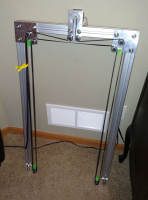
Here's the Z axis frame, put together but waiting for the T-nuts to mount the linear guides:
I'll be picking up the 8mm bed plate material today. Time to start building the rest of the frame...
Ultra MegaMax Dominator 3D printer: [drmrehorst.blogspot.com]
|
Re: My coreXY design is progressing to the build stage December 14, 2016 09:26AM |
Registered: 9 years ago Posts: 1,873 |
The makerspace sounds fantastic. It restores some of my faith in people that it works the way you describe - long may it continue!
Your build is looking great. I hope to make a start on mine over the Christmas break, but I still have lots of design work to flesh out. Sadly the amount of time and energy I can find recently hasn't been up to a major project like the new printer, so progress has been minimal.
Your build is looking great. I hope to make a start on mine over the Christmas break, but I still have lots of design work to flesh out. Sadly the amount of time and energy I can find recently hasn't been up to a major project like the new printer, so progress has been minimal.
|
Re: My coreXY design is progressing to the build stage December 14, 2016 04:48PM |
Registered: 10 years ago Posts: 770 |
|
Re: My coreXY design is progressing to the build stage December 14, 2016 06:30PM |
Registered: 11 years ago Posts: 5,780 |
The t-nuts arrived today and the Z axis linear guides are now screwed down. I have to make the L brackets and cross bar and then I can start testing the Z axis. I picked up the bed plate material and will have to cut and mill it to size and drill it for the support screws.
Ultra MegaMax Dominator 3D printer: [drmrehorst.blogspot.com]
Ultra MegaMax Dominator 3D printer: [drmrehorst.blogspot.com]
|
Re: My coreXY design is progressing to the build stage December 16, 2016 07:41PM |
Registered: 11 years ago Posts: 5,780 |
I made the L brackets and cross arm today and screwed them to the bearing blocks and did a quick test. I made no effort to align anything- just screwed it all together:
First test of Z axis mechanism
I'll print some belt clamps and connect it to a controller this weekend. Stay tuned for updates.
Ultra MegaMax Dominator 3D printer: [drmrehorst.blogspot.com]
First test of Z axis mechanism
I'll print some belt clamps and connect it to a controller this weekend. Stay tuned for updates.
Ultra MegaMax Dominator 3D printer: [drmrehorst.blogspot.com]
|
Re: My coreXY design is progressing to the build stage December 17, 2016 04:44PM |
Registered: 11 years ago Posts: 5,780 |
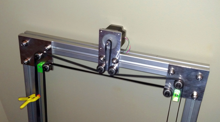
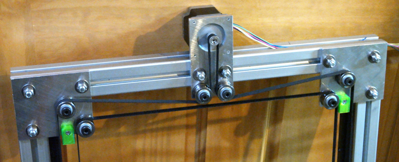
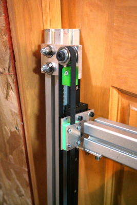
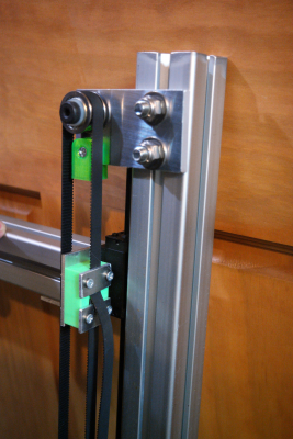
Belt clamps printed, belt installed and tensioned. I clamped the belt with the cross arm at the bottom of the axis, resting on the bumpers. When I run the thing up and down manually, it goes right back to the bottom in perfect alignment. I'll be connecting it to a controller and mounting a laser on the cross bar to check for small angular errors (walking on the rails) later today.
In SoM, my other printer, I designed an elaborate X axis belt tensioner that had a screw to adjust the belt tension. While it worked, I found that with time and tension and heat, the frame of the tensioner flexed. I eventually replaced that with a much less adjustable aluminum part. I kept it simple this time- I copied this belt clamp design from my CubeX printer. The belt doesn't need to get tensioned or adjusted on a frequent basis so it's pointless to design a part as if it did. This clamp/tensioner has no moving parts. Just clamp one end of the belt tightly, then loop the belt through all the other pulleys and bring the free end back to this clamp. Twist it tight with a pair of pliers and screw the clamp down on it. Done. The printed piece (bright green) has teeth that mesh with the teeth on the belt so it can't slip.
Ultra MegaMax Dominator 3D printer: [drmrehorst.blogspot.com]
Sorry, only registered users may post in this forum.
