My coreXY design is progressing to the build stage
Posted by the_digital_dentist
|
Re: My coreXY design is progressing to the build stage January 13, 2017 12:50AM |
Registered: 7 years ago Posts: 249 |
Looks stout 
If you're paneling the sides (clear), inside corner braces are kinda moot. Except where your door will be, then you'll probably still have short panels above and below for a seal interface. May be even an over and under cabinet arrangement, so you can access the top without opening the build chamber? Heaters at the bottom, vents on the top is the way most industrial printers are done. That is if you're still going to box it in.
I'm liking the 4040 rail tower, and the skate wheels. The belted Z is brave, though with that much Z can see the advantage over a screw, as long length to diameters tend to whip as they're typically not very straight.
From earlier post you were shooting for 300 sq x 700 tall print volume, mission accomplished?
|
Re: My coreXY design is progressing to the build stage January 13, 2017 08:12AM |
Registered: 11 years ago Posts: 5,780 |
Yes, 300x300x700 build envelope, single extruder, enclosed for printing ABS. I will put a 500W heater at the bottom with a fan or two at the ends of tubes in one or two corners to suck air from the top of the enclosure and bring it back to the bottom. The 8mm cast aluminum tooling plate bed will have a line powered 750 W heater and PEI surface.
The skate wheels work extremely well, but the assembly is pretty ugly. Every time I look at it my ankles hurt as if I had walked by and kicked one of those bolts sticking out. Ouch! I think I'll use a single piece of 1/4" or more aluminum to mount the wheels on the inside of the frame and cantilever the axle. It will look better and will be less likely to cause any injuries, real or imagined.
Ultra MegaMax Dominator 3D printer: [drmrehorst.blogspot.com]
|
Re: My coreXY design is progressing to the build stage January 13, 2017 10:36AM |
Registered: 7 years ago Posts: 249 |

|
Re: My coreXY design is progressing to the build stage January 13, 2017 12:35PM |
Registered: 11 years ago Posts: 5,780 |
I have a 450W heater on my other printer with a 1/4" tooling plate bed and it takes 5-6 minutes to get to 105C. This one will have an 8mm bed so I'm expecting about the same warm-up time with the extra power.
Ultra MegaMax Dominator 3D printer: [drmrehorst.blogspot.com]
Ultra MegaMax Dominator 3D printer: [drmrehorst.blogspot.com]
|
Re: My coreXY design is progressing to the build stage January 14, 2017 10:12AM |
Registered: 11 years ago Posts: 5,780 |
The 40x40 mm t-slot extrusions don't actually have a flat surface for the Z axis linear guide rails to sit on. There is a slight concavity designed into the extrusion. If you screw a relatively thick, flat plate to the extrusion, the inner "rails" will deform slightly when the bolt is tightened, providing a spring force to lock the bolt. When I placed the Z axis linear guides on the extrusion for testing I found that the concavity created a problem as the rail had no stable place to sit on the unflat surface of the extrusion.
This is a close-up of how the rail would sit on the extrusion:
When I made the motor mounting plate for the Rino worm drive, I also milled some flats into the surface of the vertical extrusions where the guide rails mount.
Here's what the rail will look like when sitting on the milled flat surface:
And here's what it actually looks like on the assembled Z axis. You can see where I milled the flat just above the end of the guide rail:
The milled flats are only cut 0.25 mm into the surfaces of the extrusions, but they provide stable, known-flat surfaces for the linear guides to sit on.
When I reassembled the Z axis and tested it, again without any effort to align things, the cross bar moved smoothly up and down the full length of the guide rails. When I bolted the Z axis into the machine's frame and checked it, motion was perfectly smooth from top to bottom.
Edited 1 time(s). Last edit at 01/14/2017 10:29AM by the_digital_dentist.
Ultra MegaMax Dominator 3D printer: [drmrehorst.blogspot.com]
This is a close-up of how the rail would sit on the extrusion:

When I made the motor mounting plate for the Rino worm drive, I also milled some flats into the surface of the vertical extrusions where the guide rails mount.
Here's what the rail will look like when sitting on the milled flat surface:

And here's what it actually looks like on the assembled Z axis. You can see where I milled the flat just above the end of the guide rail:

The milled flats are only cut 0.25 mm into the surfaces of the extrusions, but they provide stable, known-flat surfaces for the linear guides to sit on.
When I reassembled the Z axis and tested it, again without any effort to align things, the cross bar moved smoothly up and down the full length of the guide rails. When I bolted the Z axis into the machine's frame and checked it, motion was perfectly smooth from top to bottom.
Edited 1 time(s). Last edit at 01/14/2017 10:29AM by the_digital_dentist.
Ultra MegaMax Dominator 3D printer: [drmrehorst.blogspot.com]
|
Re: My coreXY design is progressing to the build stage January 15, 2017 11:41AM |
Registered: 11 years ago Posts: 5,780 |
I think I have the bed levelers worked out. The pink block is either teflon or torlon cut to fit in the 8 mm wide slot in the extrusion (I may mill the slot wider to accommodate a wider piece of teflon/torlon) and held in place with 2 screws. The leveling screw has a spherical head and is screwed into the teflon/torlon which grips it tightly. The bed plate will be drilled through and will have a countersink cone that contacts the spherical screw head and allows it to pivot without binding. The hex socket in the screw head will be accessible from the top of the bed plate to allow leveling adjustments. A spring will keep the bed plate pulled hard against the spherical screw head. The spring will be hung on two screws, one that goes into the edge of the bed plate and the other into a nylon (green) screw anchor in the center hole of the extrusion. There will, of course, be exactly three of these adjusters.
I'll need to find suitable springs- we have a lot of them at the makerspace, so I don't anticipate any problems with that. I have plenty of teflon/torlon and I have the spherical head screws.
The only concern with any of this is the nylon screw anchor's behavior as the enclosure heats up. If they soften I can always install the 5/16-18 screws that I use to screw the extrusions together.
Edited 1 time(s). Last edit at 01/15/2017 11:44AM by the_digital_dentist.
Ultra MegaMax Dominator 3D printer: [drmrehorst.blogspot.com]
|
Re: My coreXY design is progressing to the build stage January 15, 2017 07:30PM |
Registered: 11 years ago Posts: 5,780 |
I got a good portion of the bed support done today and expect to have the bed finished tomorrow or Tuesday. I ended up using the Torlon for the bed support screws but will have to modify the design a little- the screws that hold the Torlon in place protrude into the axial hole in the 4040 extrusion, so I'll have to figure out a different place to hook the springs. Torlon is tough stuff to work with, especially compared to teflon.
Ultra MegaMax Dominator 3D printer: [drmrehorst.blogspot.com]


Ultra MegaMax Dominator 3D printer: [drmrehorst.blogspot.com]
|
Re: My coreXY design is progressing to the build stage January 15, 2017 07:49PM |
Registered: 9 years ago Posts: 1,873 |
Interesting design. My initial reaction was that it seemed a little over-complicated, but looking again it seems easy enough to construct, and the usability should be excellent. I can't actually think of any down-sides, so I think this gets a 
I've not seen those screws before, I'll have to have a search for them.
Edit: Ah, used in RC models, and I think sometimes in delta printers. Fairly readily available on ebay, eg. [www.ebay.ca]
Edited 1 time(s). Last edit at 01/15/2017 08:25PM by JamesK.
I've not seen those screws before, I'll have to have a search for them.
Edit: Ah, used in RC models, and I think sometimes in delta printers. Fairly readily available on ebay, eg. [www.ebay.ca]
Edited 1 time(s). Last edit at 01/15/2017 08:25PM by JamesK.
|
Re: My coreXY design is progressing to the build stage January 15, 2017 11:24PM |
Registered: 11 years ago Posts: 5,780 |
Unfortunately, they are cheap screws made of soft steel. If you apply too much torque the 2.5 mm hex sockets strip out, so I had to use slightly over-sized holes and then tapped them so that it wouldn't take too much torque to turn the screws into the Torlon. In hindsight, I think teflon would have been better, but it's done now and should be OK.
That ebay listing doesn't say anything about the size. I bought mine via amazon.com because they specified that they are M5 screws.
This is a new design for me and if I decide it sucks for one reason or another I'll revert to my previous design using flat head screws countersunk into the plate. I'll be countersinking the bottom side of the plate for these ball-heads to sit in, so if it has to change, I'll just flip over the plate and it will be ready to go.
There are a couple potential problems with this design for the levelers. If the holes in the bed plate don't match up almost exactly with the location of the ball screw heads, the conical holes in which the ball heads sit will create lateral forces that will try to shift the bed plate. It may not find a stable position and keep shifting with temperature cycling. Likewise when the bed heats up and expands, the expansion against the ball heads may cause the bed to lift, also because of the conical holes. Then there's the transport issue. If the machine is tilted to move it, the bed may shift on the leveling screws causing one side or another to lift up. I don't like having to level the bed more than once every few months to a year, so we'll see how it goes. I still have no idea how the belt drive Z axis is going to behave in this regard and I may end up scrapping the whole thing in favor of one driven by screws.
Edited 2 time(s). Last edit at 01/16/2017 12:50AM by the_digital_dentist.
Ultra MegaMax Dominator 3D printer: [drmrehorst.blogspot.com]
|
Re: My coreXY design is progressing to the build stage January 16, 2017 01:21AM |
Registered: 7 years ago Posts: 249 |
Another solution would be tooling balls, shanks pressed into the bed (they're always hardened and ground), and cups on jack screws from the frame/support. The jacks even could over hang the end of the aluminum extrusions for easy access.
Down side, tooling balls are pricey, and you need three.
An opportunity for improvement is the leveling legs. Why so narrow? Currently, there's 3 stress risers: the tapped hole on the end, the vertical thru hole and the sharp connecting corners. Better the leveling points were completely under the main body of the bed, or at least have full 45 gussets?
However, there's nothing wrong with soft ball heads, as long as the mating part is either significantly harder, or softer, they will hold up fine mechanically (aside from stripping the hex). It's not like they're being subjected to impacts or high surface speeds.
Still investigating bed leveling myself, so it's good to see lots of options. Thanks for sharing.
|
Re: My coreXY design is progressing to the build stage January 16, 2017 02:02AM |
Registered: 11 years ago Posts: 5,780 |
Stress risers are a concern if there's a lot of force on the plate, but other than it's own weight and a few kg pull from the springs, there isn't much to speak of. The plate is 8mm thick. The inside corners will be rounded because I'll be cleaning up the cuts with a mill. I added the ears to put the leveling screws outside the printable area. The ears are narrow to minimize the amount of heat they suck away from the edges of the bed plate. The ball head screws, being steel, won't transfer a lot of heat, and they are driven into Torlon blocks to further reduce heat transfer to the undercarriage. Torlon is good up to about 260C, about 100C higher than the bed will ever be set. I'll be adding a thermal cut-off to the side of the bed plate that will limit the maximum temperature (as long as the adhesive holding the heater to the bed plate keeps the two stuck together).
I may change the way the torlon blocks are held in place- instead of two vertical screws, two horizontal screws might be better. Right now the blocks are in fixed positions. If the holes in the bed plate don't match up exactly I could have a stability problem. If I let the Torlon blocks slide a little in their slots, I can put the bed plate down on them, forcing them to slide into alignment with the holes in the bed plate, then tighten them down from the side. That will also open up the axial hole in the extrusion so I can put the spring anchor there as originally designed. Hmmm....
Edited 1 time(s). Last edit at 01/16/2017 02:09AM by the_digital_dentist.
Ultra MegaMax Dominator 3D printer: [drmrehorst.blogspot.com]
|
Re: My coreXY design is progressing to the build stage January 16, 2017 02:49AM |
Registered: 7 years ago Posts: 249 |
Yea, if you're milling it out, radius is a given. Lots of choices for process these days. True, 8 mm is kinda thick, and for printing more than strong enough. It's when brute force is needed to remove prints, that bending or breaking happens.
Without even a thermal analysis, being narrow, the legs are actually better at pulling heat. With a higher surface area to volume ratio, are more likely to create cold spots on the edge of the heat bed, than if they were large triangular bits able to maintain core temps.
Torlon is a great high temp plastic, easy to machine like acetal (delrin). About the only better structural insulator I've used is G11 garolite, though difficult to cut or tap.
Thinking about using G11 for my sub plate, and place the heat bed and mirror on top for the build surface. Having an insulator under the heater helps stability and lowers the time to reach temp.
From what I gather, you're gluing the heater under the 8mm plate. Any plans for insulation under that?
|
Re: My coreXY design is progressing to the build stage January 16, 2017 08:42AM |
Registered: 11 years ago Posts: 5,780 |
Even with stress risers, I think I'd have a hard time applying enough force to break an 8mm plate by removing a stuck print.
Also without conducting a thermal analysis, common sense tells me that wider ears would transfer more heat away from the edge of the bed. The quantity of heat transferred is about cross section and surface area. The efficiency may be about the ratio of the volume to surface area, but we're not interested in efficiency here, just total heat transferred. Think about the limit cases- zero width ears would transfer no heat and ears as wide as the plate would transfer a lot of heat. This is somewhere between the two, closer to the former than the latter. Think about how ICs are designed. If tiny cross section conductors transferred more heat than large area conductors, they would use bond wires to take the heat out of ICs instead of mounting the chip on a metal substrate.
With an 8mm plate, cool down time will already be pretty long, so I'm not planning to add any extra insulation. The silicone heater itself acts as an insulator when it isn't heating the plate. Adequate heater power (750W, about 1 W per cm^3) means the plate will heat up quickly enough without insulation. Any heat "lost" from the bottom of the plate will help warm the enclosure to keep the ABS prints happy. I'll be adding a 500W enclosure heater, too.
Here's what the whole thing looks like so far:
It stands 146 cm tall and easily fits through doorways. The skate wheel casters make it very easy to move around.
Edited 3 time(s). Last edit at 01/16/2017 12:57PM by the_digital_dentist.
Ultra MegaMax Dominator 3D printer: [drmrehorst.blogspot.com]
Also without conducting a thermal analysis, common sense tells me that wider ears would transfer more heat away from the edge of the bed. The quantity of heat transferred is about cross section and surface area. The efficiency may be about the ratio of the volume to surface area, but we're not interested in efficiency here, just total heat transferred. Think about the limit cases- zero width ears would transfer no heat and ears as wide as the plate would transfer a lot of heat. This is somewhere between the two, closer to the former than the latter. Think about how ICs are designed. If tiny cross section conductors transferred more heat than large area conductors, they would use bond wires to take the heat out of ICs instead of mounting the chip on a metal substrate.
With an 8mm plate, cool down time will already be pretty long, so I'm not planning to add any extra insulation. The silicone heater itself acts as an insulator when it isn't heating the plate. Adequate heater power (750W, about 1 W per cm^3) means the plate will heat up quickly enough without insulation. Any heat "lost" from the bottom of the plate will help warm the enclosure to keep the ABS prints happy. I'll be adding a 500W enclosure heater, too.
Here's what the whole thing looks like so far:

It stands 146 cm tall and easily fits through doorways. The skate wheel casters make it very easy to move around.
Edited 3 time(s). Last edit at 01/16/2017 12:57PM by the_digital_dentist.
Ultra MegaMax Dominator 3D printer: [drmrehorst.blogspot.com]
|
Re: My coreXY design is progressing to the build stage January 17, 2017 04:01AM |
Registered: 9 years ago Posts: 31 |
Impressive build log, almost impressive as the build itself. I respect the careful and well-reasoned design approach.
Physics experiments involving lasers often have complicated optical setups where everything is mounted on adjustable tables for beam alignment:
Typically the "middle" corner has a ball bearing sitting in a countersunk recess constraining it along three axes, as in your bed-mount design (center in the above image); the next corner has a micron thread with a hemispherical end sitting against a linear groove, constraining it along two axes (left); and the third corner has the same hemispherical micron thread sitting against a flat plate, constraining it along only one axis (right). Strong springs hold the piece together. By adjusting the two micron threads on opposite corners, this system allows for full angular adjustment without over-constraint.
This system might make for a more reliable bed mount, as long as you can find strong-enough springs.
Physics experiments involving lasers often have complicated optical setups where everything is mounted on adjustable tables for beam alignment:

Typically the "middle" corner has a ball bearing sitting in a countersunk recess constraining it along three axes, as in your bed-mount design (center in the above image); the next corner has a micron thread with a hemispherical end sitting against a linear groove, constraining it along two axes (left); and the third corner has the same hemispherical micron thread sitting against a flat plate, constraining it along only one axis (right). Strong springs hold the piece together. By adjusting the two micron threads on opposite corners, this system allows for full angular adjustment without over-constraint.
This system might make for a more reliable bed mount, as long as you can find strong-enough springs.
|
Re: My coreXY design is progressing to the build stage January 17, 2017 04:01AM |
Registered: 7 years ago Posts: 11 |
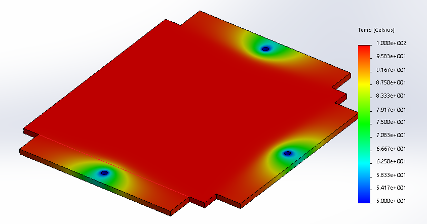
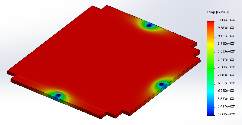
I think the point he was trying to make about the "ears" vs. a wider shape is that with the "ears", while less energy will be lost the cold spot would be more concentrated. With a wider mount more energy would be lost, but also the cooled area would be spread out; this could mean that the maximum temperature drop be lower.
This doesn't seem to hold though. I did some simulations over my breakfast with a (8mm x 300mm x 300mm) aluminium plate with ears of sizes (40mm x 250mm), (20mm x 250mm), and (20mm x 15mm). Back side of the plate is held at 100C, mounting holes at 50C. Simulation is without radiation and convection.
I'd be more worried about thermal expansion. a 100C difference over 300mm is ~0.7mm (given an expansion coefficient of 22.2um/(m K))
I really enjoy following the build process of a quality printer.
|
Re: My coreXY design is progressing to the build stage January 17, 2017 08:37AM |
Registered: 11 years ago Posts: 5,780 |
Interesting optical aligner. I think I can use that idea...
All three supports will be constrained in Z by springs pulling them down to the support structure. One support, left, will also be constrained in X and Y, by sitting in a conical hole. The support to the right will sit in a slot that will constrain it in Y and allow for thermal expansion in X, and the third point will be unconstrained in X and Y allowing for thermal expansion. I like this a lot! The two points along the X axis will use the ball head screws and be adjustable from above the plate (though the left one will be the "reference" and will only be adjusted once to set the z=0 position) to set the pitch in the X axis. The third support will be adjustable from under the support structure to set the roll. This is great! I'm going to use it. Thanks for that inspiration!
This method would not have worked well in my other machine because the massive bed plate was moving in the Y axis, subjecting it to lateral forces every time it changed direction. In the corexy, the bed only moves vertically, and does so slowly. This technique should work well.
The only potential problem is the mass of the plate- I have two casters to move the machine and will have to tilt it to move it. Transporting it in my car will require laying it on it's side, so I'll have to be extra careful to secure the bed plate to keep it from moving around too much. That's a minor problem, easily dealt with by bungee cords or similar methods.
Edited 1 time(s). Last edit at 01/17/2017 11:17AM by the_digital_dentist.
Ultra MegaMax Dominator 3D printer: [drmrehorst.blogspot.com]
|
Re: My coreXY design is progressing to the build stage January 17, 2017 08:43AM |
Registered: 11 years ago Posts: 5,780 |
Regarding thermals, convection is going to be a big part of the behavior. The applied heat ends abruptly at the edges of the plate, and the plate is about 55-60C above the surrounding air temperature (105C plate in 50C enclosure),so convection is going to be a strong force to cool the edges of the plate. If you're going to simulate it, ignoring convection will probably lead to errors.
Edited 1 time(s). Last edit at 01/18/2017 12:18AM by the_digital_dentist.
Ultra MegaMax Dominator 3D printer: [drmrehorst.blogspot.com]
Edited 1 time(s). Last edit at 01/18/2017 12:18AM by the_digital_dentist.
Ultra MegaMax Dominator 3D printer: [drmrehorst.blogspot.com]
|
Re: My coreXY design is progressing to the build stage January 17, 2017 04:32PM |
Registered: 7 years ago Posts: 249 |
Considering you have a heated enclosure, can't see there's going to be a significant heat loss in the ears. Plus, they'll have fillets, not sharp corners like your models, so stress is no longer a concern for me. Not that that matters, given its 8mm thick
Yep, thermal expansion. The heated enclosure will keep the differential between the bed and Z-frame to around 0.4 mm total, for a 300 mm span by my calcs. Leveling the bed when everything is at temp will be the hard part.
Having the long Z belts in the heat might be a small issue. Probably not worth worrying about. Adding spring tensioner/pulley will eliminate any lash, if you experience any.
|
Re: My coreXY design is progressing to the build stage January 18, 2017 08:55PM |
Registered: 11 years ago Posts: 5,780 |
I cut the bed plate, milled the edges, drilled holes and set it up as previously described. The two X axis levelers are spherical head screws, the left most is set into a conical depression in the bed plate (actually a hole drilled through and bored with a countersink bit into a conical shape), constraining the bed in X and Y. The right side has a 3mm long slot which constrains the bed inthe Y axis but allows for thermal expansion in the X axis, and the third support currently has a spherical head screw resting on the flat plate but will be replaced by a thumbscrew that adjusts from below, unconstrained in X and Y to allow for thermal expansion. All points are constrained in the Z axis by the plate's weight and the springs that hold it down against the supports.
Here's the center support that will be used to adjust the roll around the X axis. The spherical head screw (behind the spring) will be replaced with a thumbscrew:
The left and center supports. The left support sits in the conical hole:
The left side support viewed from the underside:
Another view of the left side support:
I couldn't find three identical springs at the makerspace or in my own stash, so I'll be looking for replacements for purely cosmetic reasons.
Yes, I know, the milling is sloppy.
Edited 1 time(s). Last edit at 01/18/2017 09:09PM by the_digital_dentist.
Ultra MegaMax Dominator 3D printer: [drmrehorst.blogspot.com]
Here's the center support that will be used to adjust the roll around the X axis. The spherical head screw (behind the spring) will be replaced with a thumbscrew:

The left and center supports. The left support sits in the conical hole:

The left side support viewed from the underside:

Another view of the left side support:

I couldn't find three identical springs at the makerspace or in my own stash, so I'll be looking for replacements for purely cosmetic reasons.
Yes, I know, the milling is sloppy.
Edited 1 time(s). Last edit at 01/18/2017 09:09PM by the_digital_dentist.
Ultra MegaMax Dominator 3D printer: [drmrehorst.blogspot.com]
|
Re: My coreXY design is progressing to the build stage January 18, 2017 09:03PM |
Registered: 9 years ago Posts: 1,873 |
|
Re: My coreXY design is progressing to the build stage January 18, 2017 09:06PM |
Registered: 11 years ago Posts: 5,780 |
Oh yeah, new cantilevered caster design (if you can call a flat plate with 3 holes a design):
Edited 1 time(s). Last edit at 01/19/2017 07:11AM by the_digital_dentist.
Ultra MegaMax Dominator 3D printer: [drmrehorst.blogspot.com]

Edited 1 time(s). Last edit at 01/19/2017 07:11AM by the_digital_dentist.
Ultra MegaMax Dominator 3D printer: [drmrehorst.blogspot.com]
|
Re: My coreXY design is progressing to the build stage January 18, 2017 09:17PM |
Registered: 9 years ago Posts: 1,873 |
|
Re: My coreXY design is progressing to the build stage January 18, 2017 10:05PM |
Registered: 11 years ago Posts: 5,780 |
just 1/4" tooling plate. Seems to be working fine. It's significantly thicker than the material on the side of the extrusion that it is bolted to.
Ultra MegaMax Dominator 3D printer: [drmrehorst.blogspot.com]
Ultra MegaMax Dominator 3D printer: [drmrehorst.blogspot.com]
|
Re: My coreXY design is progressing to the build stage January 18, 2017 10:16PM |
Registered: 9 years ago Posts: 1,873 |
|
Re: My coreXY design is progressing to the build stage January 19, 2017 07:08AM |
Registered: 11 years ago Posts: 5,780 |
The wheel is 73 mm diameter, and the extrusion is 40 mm square.
Ultra MegaMax Dominator 3D printer: [drmrehorst.blogspot.com]
Ultra MegaMax Dominator 3D printer: [drmrehorst.blogspot.com]
|
Re: My coreXY design is progressing to the build stage January 23, 2017 03:51PM |
Registered: 8 years ago Posts: 88 |
I'm watching closely your build and stealed and adapted some ideas for my attempt at at a CoreXY.
Anyway, one noticeable thing I want to thank you for:
This is a 320x320x8mm cast aluminium, milled flat with a 600w 300x300mm silicone heater under it, no enclosure yet.
Target temp was 115 deg. C, so not far off. I've made a custom thermistor location.
Anyway, one noticeable thing I want to thank you for:

This is a 320x320x8mm cast aluminium, milled flat with a 600w 300x300mm silicone heater under it, no enclosure yet.
Target temp was 115 deg. C, so not far off. I've made a custom thermistor location.

|
Re: My coreXY design is progressing to the build stage January 23, 2017 03:59PM |
Registered: 11 years ago Posts: 5,780 |
Sweet! You can't beat an aluminum bed for even heating.
Ultra MegaMax Dominator 3D printer: [drmrehorst.blogspot.com]
Ultra MegaMax Dominator 3D printer: [drmrehorst.blogspot.com]
|
Bed plate details January 23, 2017 11:07PM |
Registered: 11 years ago Posts: 5,780 |
Top view of the bed plate, looking down through the XY stage. The X axis is horizontal and Y axis vertical:
The hole on the left ear is the tool access hole for the reference leveling adjuster. The short slot in the right ear is for the pitch adjuster, and the ear at the bottom is for the roll adjuster. There's no hole there- it will be adjusted from the bottom side of the bed using a thumbscrew.
In all these photos below, you're seeing the underside of the bed plate.
Underside of the bed at the reference screw hole:
The spherical head screw sits inside the conical hole, constraining it to tilt only, no lateral movement in X, Y. A spring, not shown, constrains motion in Z:
The reference height will be adjusted using a hex key from the top side of the bed. The small, threaded hole in the edge of the plate is for a screw for the hold-down spring.
Underside of the bed at the pitch screw slot:
The pitch adjuster spherical screw head sits in the chamfer around the edge of the X axis parallel slot:
The chamfer allows the bed to expand in X and pivot, but prevents lateral motion in the Y direction. A hold down spring constrains Z motion. Roll will be adjusted using a hex key from the top side of the bed. I should probably have made the chamfer a little wider so the screw would sit a little deeper in it. Maybe I'll tweak it tomorrow.
The roll adjuster:
The roll adjuster passes through the undercarriage. The bed plate just rests on the screw- the bed is free to tilt and expand in X and Y while a hold-down spring (not shown) constrains Z motion. Maybe I'll round off the top of the screw or screw on an acorn nut.
Ultra MegaMax Dominator 3D printer: [drmrehorst.blogspot.com]

The hole on the left ear is the tool access hole for the reference leveling adjuster. The short slot in the right ear is for the pitch adjuster, and the ear at the bottom is for the roll adjuster. There's no hole there- it will be adjusted from the bottom side of the bed using a thumbscrew.
In all these photos below, you're seeing the underside of the bed plate.
Underside of the bed at the reference screw hole:

The spherical head screw sits inside the conical hole, constraining it to tilt only, no lateral movement in X, Y. A spring, not shown, constrains motion in Z:

The reference height will be adjusted using a hex key from the top side of the bed. The small, threaded hole in the edge of the plate is for a screw for the hold-down spring.
Underside of the bed at the pitch screw slot:

The pitch adjuster spherical screw head sits in the chamfer around the edge of the X axis parallel slot:

The chamfer allows the bed to expand in X and pivot, but prevents lateral motion in the Y direction. A hold down spring constrains Z motion. Roll will be adjusted using a hex key from the top side of the bed. I should probably have made the chamfer a little wider so the screw would sit a little deeper in it. Maybe I'll tweak it tomorrow.
The roll adjuster:

The roll adjuster passes through the undercarriage. The bed plate just rests on the screw- the bed is free to tilt and expand in X and Y while a hold-down spring (not shown) constrains Z motion. Maybe I'll round off the top of the screw or screw on an acorn nut.
Ultra MegaMax Dominator 3D printer: [drmrehorst.blogspot.com]
|
Re: My coreXY design is progressing to the build stage January 24, 2017 12:47AM |
Registered: 7 years ago Posts: 249 |
Seems odd you didn't put the X leveling arms as far from the single Y pivot as possible. Adjusting the Y will result in the greatest change in roll ATM.
Plus, you're gonna to have to rely on a spring and/or position heavy builds so the CG is inside the 3 points.
Springs are cool and will probably work just peachy, yet having been a machinist, and indicating in all kinds of countless stuff, last thing I'd want is a teeter totter for a bed. Though I'd gladly take the rest
|
Re: My coreXY design is progressing to the build stage January 24, 2017 08:33AM |
Registered: 9 years ago Posts: 1,873 |
Quote
prot0typ1cal
Springs are cool and will probably work just peachy, yet having been a machinist, and indicating in all kinds of countless stuff, last thing I'd want is a teeter totter for a bed. Though I'd gladly take the rest
It's probably not too difficult to find a spring for the Y adjustment point that produces an order of magnitude more force than produced by the out of balance weight of any reasonable print. There would be no good reason to only print on the unsupported half of the bed after all, and any large heavy print will likely be centered. I doubt if there will be an issue in practice for FDM tolerances. The plus side of the layout is it puts the lifting points in line with the bed CofG with a minimum amount of extra structure. As long as the bed is sufficiently stiff it should work well. It sure looks saner than the big cantilever I'm trying to make


Sorry, only registered users may post in this forum.