My coreXY design is progressing to the build stage
Posted by the_digital_dentist
|
Re: My coreXY design is progressing to the build stage January 31, 2017 11:24AM |
Registered: 7 years ago Posts: 8 |
|
Re: My coreXY design is progressing to the build stage January 31, 2017 06:24PM |
Registered: 11 years ago Posts: 1,049 |
IMU set up test (MPU6050)
Crude ---- just using Arduino IDE tools (Monitor, Plotter)
How useful ?????
Data can be captured in file
data coming out precise (got to grab it as long float or something)
just got to display it
Raw gyro / accel, Quaternion, Euler etc?
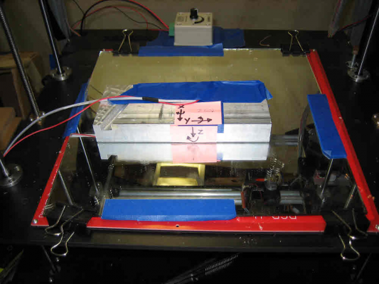
IMU on block of aluminum on bed of my FT5
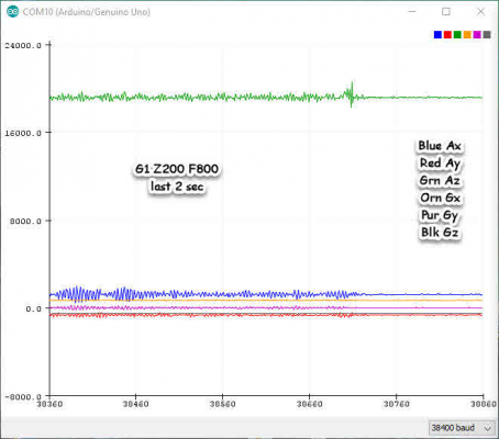
Plot from Z axis move
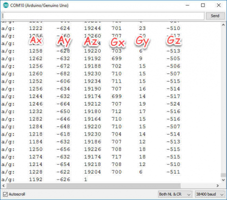
Data from Z axis move

|
Re: My coreXY design is progressing to the build stage February 01, 2017 03:48PM |
Registered: 11 years ago Posts: 5,780 |
I've been looking into accelerometer and gyro chips. The resolution and noise of most would not allow measurement to 0.01 degrees of static tilt. This one comes close: [www.analog.com]
I think I'm going to move on to just finishing the build and running test prints.
Ultra MegaMax Dominator 3D printer: [drmrehorst.blogspot.com]
I think I'm going to move on to just finishing the build and running test prints.
Ultra MegaMax Dominator 3D printer: [drmrehorst.blogspot.com]
|
Re: My coreXY design is progressing to the build stage February 01, 2017 08:16PM |
Registered: 11 years ago Posts: 1,049 |
Is static angle really what you need?
You have a dynamic system you are measuring.
Angle difficult to measure, accelaration, and rate of change much easier.
Mechanical mounting --- long arm may provide the necessary resolution?
Black art of conversion, filters and data fusion?
The MPU-60X0 features three 16-bit analog-to-digital converters (ADCs) for digitizing the gyroscope outputs
and three 16-bit ADCs for digitizing the accelerometer outputs. For precision tracking of both fast and slow
motions, the parts feature a user-programmable gyroscope full-scale range of ±250, ±500, ±1000, and
±2000°/sec (dps) and a user-programmable accelerometer full-scale range of ±2g, ±4g, ±8g, and ±16g.
Amazes me you can get a precision IMU for $5

|
Re: My coreXY design is progressing to the build stage February 01, 2017 10:18PM |
Registered: 11 years ago Posts: 5,780 |
I'm trying to measure tilt from one Z position to another. Static tilt at each position is of greatest interest. I don't much care if it tilts while it's moving, but when it stops I want it to quickly settle into a level position. What defines a "position"? Is every microstep a position, or do more practical values such as the expected layer thicknesses define the steps from one position to the next? My head hurts...
Ultra MegaMax Dominator 3D printer: [drmrehorst.blogspot.com]
Ultra MegaMax Dominator 3D printer: [drmrehorst.blogspot.com]
|
Re: My coreXY design is progressing to the build stage February 02, 2017 06:43AM |
Registered: 9 years ago Posts: 5 |
|
Re: My coreXY design is progressing to the build stage February 02, 2017 11:54AM |
Registered: 7 years ago Posts: 11 |
In regards to using an IMU to measure the change in static tilt I am fairly certain from my experience with accelerometers that you will not get even close to 0.01 degrees of accuracy (the resolution might be there though). This is due to the bias drift.
At angles close to no tilt, the tilt in radians is directly proportional to the change of measured specific force (acceleration + gravity) measured in G.
This means that if you want to compare the tilt at position 'a' with the tilt at position 'b', the bias must not drift more than 0.17mG (0.01 degrees in radians times the gravitational acceleration) over the time your experiment takes.
I think you can assume that the function describing tilt at different positions is continuous, thus measuring the tilt at points spaced closely enough apart will let you derive the tilt in between. This is of cause if the tilt at specific positions is repeatable, and not influenced by eg. the direction you approach the position from.
Your best option is probably to go with the laser, and use that to amplify the tilt error. Instead of pointing the laser at the ceiling, you could point it at a far away wall allowing you to get close and inspect the results. This would also allow you to detect rotation around the vertical axis, which I would assume is far more prominent than tilt.
You can get a longer optical distance in a small space with two mirrors like this:
full article
|
Re: My coreXY design is progressing to the build stage February 02, 2017 12:40PM |
Registered: 7 years ago Posts: 249 |
|
Re: My coreXY design is progressing to the build stage February 02, 2017 02:32PM |
Registered: 10 years ago Posts: 770 |
|
Re: My coreXY design is progressing to the build stage February 02, 2017 07:06PM |
Registered: 11 years ago Posts: 5,780 |
The bed heater arrived today. 120V 750W. Made by Keenovo (China). It looks to be well made and even came with clearly written instructions. Long leads, adhesive tape applied and ready to install. Not bad...
Edited 1 time(s). Last edit at 02/02/2017 07:13PM by the_digital_dentist.
Ultra MegaMax Dominator 3D printer: [drmrehorst.blogspot.com]
Edited 1 time(s). Last edit at 02/02/2017 07:13PM by the_digital_dentist.
Ultra MegaMax Dominator 3D printer: [drmrehorst.blogspot.com]
|
Re: My coreXY design is progressing to the build stage February 02, 2017 07:18PM |
Registered: 11 years ago Posts: 1,049 |
Skrogh
help on what is coming out of IMU
Looks like a bunch of tilting going on Z axis?
What are the data coming out of IMU
Is there simpletons guide to IMU output
What to use for our application?
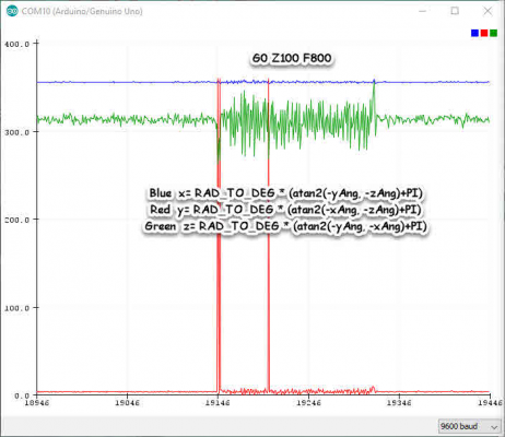
Another sketch spits out:
What are they?
ax
ay
az
gx
gy
gz
arx
ary
arz
grx
gry
grz
rx
ry
rz
tnx

help on what is coming out of IMU
Looks like a bunch of tilting going on Z axis?
What are the data coming out of IMU
Is there simpletons guide to IMU output
What to use for our application?
Another sketch spits out:
What are they?
ax
ay
az
gx
gy
gz
arx
ary
arz
grx
gry
grz
rx
ry
rz
tnx

|
Re: My coreXY design is progressing to the build stage February 03, 2017 12:22AM |
Registered: 11 years ago Posts: 5,780 |
I put the steel core HTD3 belt on it with a 32 tooth drive pulley (1000 usteps/mm) and ran it up and down for a while at different speeds. 20 mm/sec is no problem and fast enough. The HTD belt feels so much more substantial than the glass core GT2 belt.
Ultra MegaMax Dominator 3D printer: [drmrehorst.blogspot.com]
Ultra MegaMax Dominator 3D printer: [drmrehorst.blogspot.com]
|
Re: My coreXY design is progressing to the build stage February 04, 2017 12:07AM |
Registered: 11 years ago Posts: 5,780 |
I had a few very productive hours in the metal shop today. I made the extruder carriage and replacements for the bed support structure angle brackets.
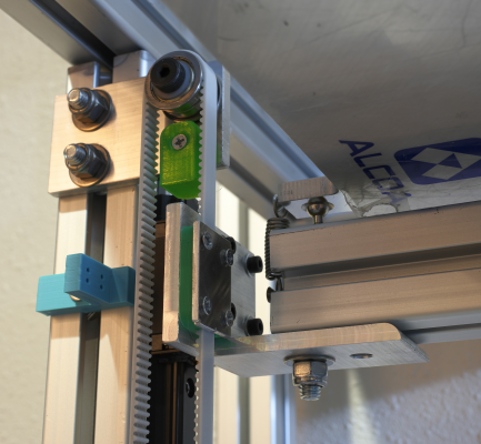
The original angle brackets were made from 2" x 2" x 1/8" angle stock. I found that when I pushed down on the bed the brackets would flex a bit and it bothered me, so I made new ones using 3" x 3" x 1/4" angle stock. I had to reprint the left side belt clamp because of the thicker bracket. The bed is much more solid now.
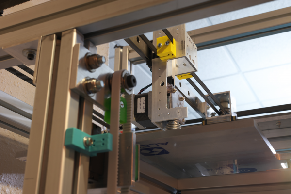
The blue piece on the left is to mount the Xmax limit switch. The bracket is identical to the one used for the Z=0 switch. I printed a part that slides onto the belt and bumps the switch when the Z axis is almost at bottom. You can see that piece attached to the belt in the next photo.
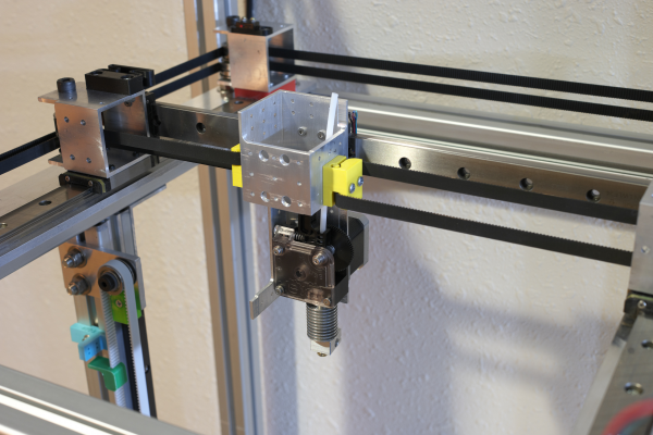
I also fabricated what I hope will be the final extruder carriage today. It is cut from a piece of the left over 2" square aluminum tubing I used for mounting the XY stage pulleys. I milled away most of the material, but left some extra here and there and drilled lots of holes to allow mounting LEDs, fans, circuit boards, and anchoring cables/drag chains. I left some of the aluminum on the left side to ensure that the whole thing remains rigid- I don't want it flexing and wobbling while it's printing.
The extra metal at the top on the left and back sides of the carriage will be for anchoring the cables and maybe mounting a circuit board.
The large hole on the left side of the carriage piece is the tool access hole to set the pinch roller tension on the extruder.
I found one problem after assembling all of it. The hot end is offset from center of the extruder carriage so far that the nozzle doesn't quite reach the left edge of the bed. My original bed support design allowed for more lateral positioning of the bed to compensate, but I neglected to update the drawings as the bed support changed. I'll look into a fix...
Edited 1 time(s). Last edit at 02/04/2017 12:21AM by the_digital_dentist.
Ultra MegaMax Dominator 3D printer: [drmrehorst.blogspot.com]
|
Re: My coreXY design is progressing to the build stage February 04, 2017 12:28PM |
Registered: 8 years ago Posts: 1,671 |
|
Re: My coreXY design is progressing to the build stage February 04, 2017 03:31PM |
Registered: 11 years ago Posts: 5,780 |
I'm staying with the bearings unless they prove to be a problem. I haven't done an exhaustive search, but I haven't seen toothed pulleys for HTD3 belt anywhere.
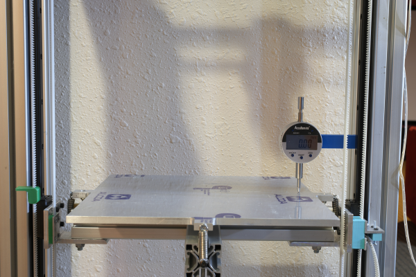
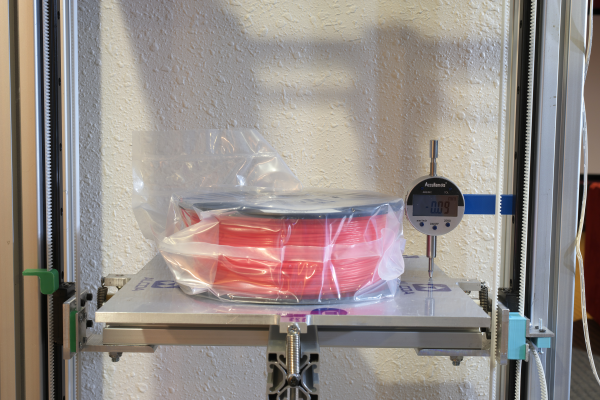
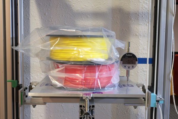
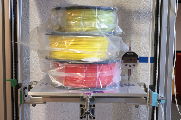
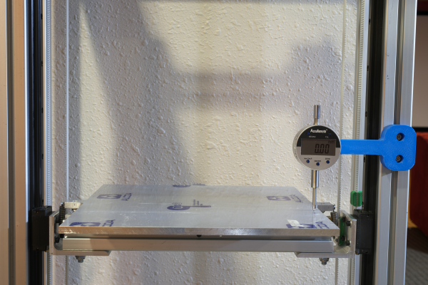
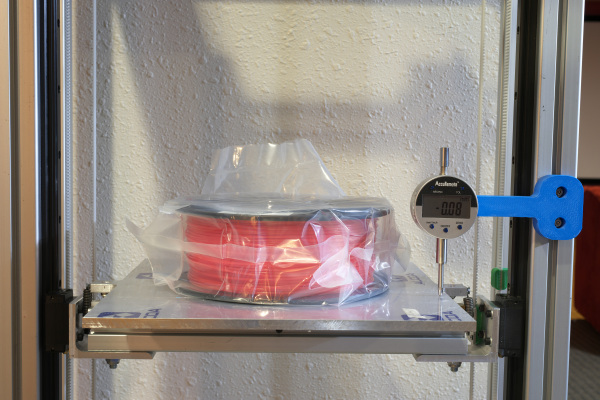
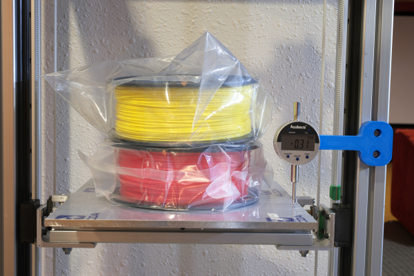
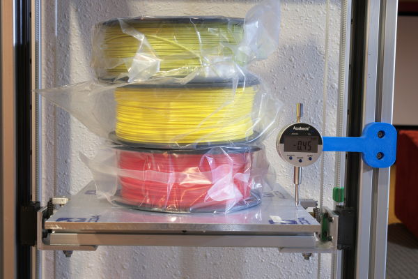
I bolted on the digital dial gauge (accuracy spec +/- 0.03 mm and repeatability +/- 0.01 mm) and tried moving the bed up and down a few mm and it behaves consistently, returning to the same level each time. I played with the acceleration and speed and found no changes in the behavior even setting the acceleration as high as 1000 mm/s/s. I haven't tried going any higher.
I also put some weight on the bed to see how much it deflects (assuming belt stretch, but other things may contribute). With 1.35 kg, the gauge indicates 0.09 mm of belt stretch. At 2.7 kg, it reads 0.26 mm. I can live with that. I don't expect actual prints to exceed 1 kg, and even if they get to 2 kgs, the total error is about 250 um (and that will be added little by little to the layers as the print gets taller and more massive). At 4 kg the stretch is about 0.5 mm. As a percentage of print height it's going to vary depending on the print morphology, but I can't see it becoming a problem.
These tests were done with the bed at about the middle of the Z axis. I ran it up and down within the dial gauge range with the 4 kg load and it had no trouble lifting and lowering it and consistently returned to the same positions.
Next question: when it's loaded, does the bed tilt? There is one common anchor point for the bed, the drive pulley. The left side belt clamp is closer in terms of belt path, to the drive pulley than the right side belt clamp. That means that when it's loaded, as the belt stretches, the platform could drop more on the right than the left, changing the pitch of the X axis. More tests coming...
Edited 2 time(s). Last edit at 02/04/2017 05:33PM by the_digital_dentist.
Ultra MegaMax Dominator 3D printer: [drmrehorst.blogspot.com]
|
Re: My coreXY design is progressing to the build stage February 04, 2017 05:32PM |
Registered: 11 years ago Posts: 5,780 |
I moved the dial gauge to the other side and reran the loading tests:
I'd say the results are pretty consistent even if the numbers aren't exactly the same. Moving on...
Ultra MegaMax Dominator 3D printer: [drmrehorst.blogspot.com]
I'd say the results are pretty consistent even if the numbers aren't exactly the same. Moving on...
Ultra MegaMax Dominator 3D printer: [drmrehorst.blogspot.com]
|
Re: My coreXY design is progressing to the build stage February 04, 2017 08:09PM |
Registered: 8 years ago Posts: 1,671 |
|
Re: My coreXY design is progressing to the build stage February 04, 2017 09:31PM |
Registered: 11 years ago Posts: 5,780 |
That's getting pretty complicated- two bearings, some sort of mount, a shaft, and a drive type pulley for each pulley in the Z axis- x8- ouch!
Edited 1 time(s). Last edit at 02/04/2017 09:50PM by the_digital_dentist.
Ultra MegaMax Dominator 3D printer: [drmrehorst.blogspot.com]
Edited 1 time(s). Last edit at 02/04/2017 09:50PM by the_digital_dentist.
Ultra MegaMax Dominator 3D printer: [drmrehorst.blogspot.com]
|
Re: My coreXY design is progressing to the build stage February 05, 2017 10:26AM |
Registered: 8 years ago Posts: 1,671 |
|
Re: My coreXY design is progressing to the build stage February 05, 2017 11:14AM |
Registered: 11 years ago Posts: 5,780 |
IRIC, I paid a little over $1 each for the F608zzs.
If one really wanted to minimize the number of pulleys, you could put the Z axis motor at either of the top corners of the Z axis and reduce the number of passive pulleys to just 5. That would be an even more asymmetric belt length arrangement than I used. The ideal arrangement would be to use two belts driven by one motor. Belts would be shorter, equal length, and only one passive pulley would be needed on each side. You'd need a drive shaft with toothed pulleys and bearings on each end- easy and cheap to arrange. Hmmm.
Edited 2 time(s). Last edit at 02/05/2017 10:03PM by the_digital_dentist.
Ultra MegaMax Dominator 3D printer: [drmrehorst.blogspot.com]
|
Re: My coreXY design is progressing to the build stage February 05, 2017 09:48PM |
Registered: 11 years ago Posts: 5,780 |
I did some review of the Z axis design, considering using two belts driven by the Rino. I calculate that with an 8mm shaft, loaded to 8 kgs, the torsion of the shaft would add about 50 um of vertical displacement to the belt stretch. It looks like a lot of what I have already done can be reused, and only a couple small parts ( a new mount for the Rino/motor, a new, longer shaft, and a couple angle brackets to mount the bearings at the bottom of each vertical) would have to be fabricated to switch to this design. Hmmmm..... I think I like the symmetry...
Edited 2 time(s). Last edit at 02/05/2017 10:05PM by the_digital_dentist.
Ultra MegaMax Dominator 3D printer: [drmrehorst.blogspot.com]
Edited 2 time(s). Last edit at 02/05/2017 10:05PM by the_digital_dentist.
Ultra MegaMax Dominator 3D printer: [drmrehorst.blogspot.com]
|
Re: My coreXY design is progressing to the build stage February 05, 2017 11:52PM |
Registered: 8 years ago Posts: 1,671 |
|
Re: My coreXY design is progressing to the build stage February 10, 2017 07:44AM |
Registered: 11 years ago Posts: 5,780 |
I ordered a long shaft and a couple pillow blocks to support the ends. I'll be converting to the simpler, two belt loop arrangement as soon as the parts arrive.
Comparing the two designs now, I'm not sure why I went with the original, except maybe that it seemed easier to make- just drill a bunch of holes and screw down a bunch of bearings. I can't really say that the new design will perform better, but the symmetry makes me think it should.
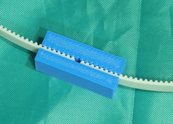
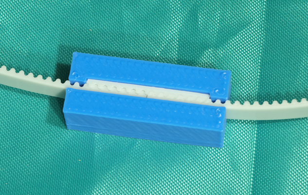
I've been testing a couple different belt clamps for the bed supports, one with a narrow, toothed slot to engage the belt and the other with a wider slot to insert a cut piece of belt that will engage the drive belt. Pulling hard on the belts with each design finds the printed-tooth version tends to flex open more than the one with the cut piece of belt inserted, so I'll probably go with a variation of that design. There will ultimately be screw holes and a metal cover that will prevent it from opening under load anyway, but starting with the stronger one seems like a good idea. The belts will be tensioned by pulling up on the pulleys at the top of the Z axis frame and tightening down their mounting bolts. It was just dumb luck that those top pulleys happen to be within 50um of their ideal positions for the new Z axis arrangement, so no modification/remake is required.
Edited 4 time(s). Last edit at 02/11/2017 07:50AM by the_digital_dentist.
Ultra MegaMax Dominator 3D printer: [drmrehorst.blogspot.com]
|
Re: My coreXY design is progressing to the build stage February 10, 2017 08:22AM |
Registered: 9 years ago Posts: 1,873 |
|
Re: My coreXY design is progressing to the build stage February 10, 2017 09:34PM |
Registered: 11 years ago Posts: 5,780 |
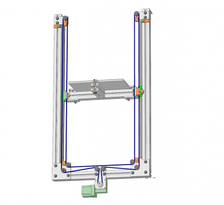
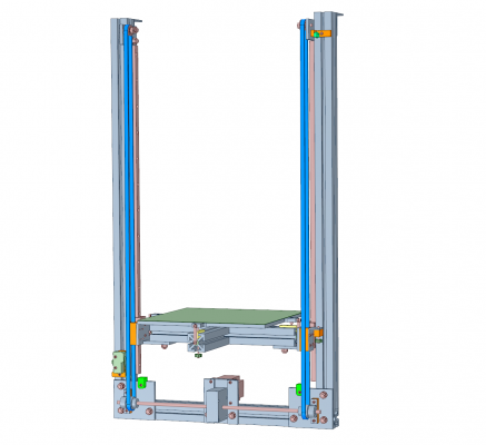
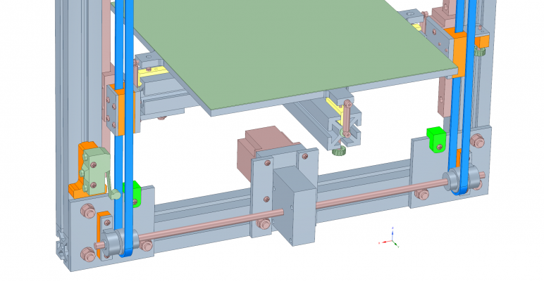
Z axis redesign recap:
The Z axis started with a NEMA-23 motor directly driving the Z axis motion, but then the problem of bed-drop became very apparent, so I replaced the direct drive motor with a 30:1 Rino worm gear reducer this way:
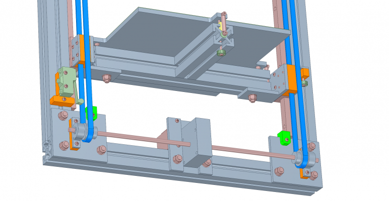
Though it looks symmetrical, the path to the motor from each of the belt clamps on the bed support cross-bar are actually quite different. Testing indicated that it should perform just fine, but the asymmetry bothered me, so I redesigned to this:
I ordered a longer shaft for the worm gear reducer and a pair of 34 tooth pulleys and pillow blocks. I remade the Rino mount- much easier this way- just a couple small plates with a few relatively small holes. The switch with the roller on the lower left is the Z max limit switch- I couldn't find another one of the tiny ones in my junk box.
I'm waiting for a few parts to arrive then I'll drill the mounting holes for the pillow blocks and move the top pulleys into position. The printed parts will be done in the next day or so and ready to drop in the moment the rest of the stuff arrives.
Edited 3 time(s). Last edit at 02/11/2017 09:44PM by the_digital_dentist.
Ultra MegaMax Dominator 3D printer: [drmrehorst.blogspot.com]
|
Re: My coreXY design is progressing to the build stage February 12, 2017 01:03PM |
Registered: 11 years ago Posts: 1,049 |
|
Re: My coreXY design is progressing to the build stage February 12, 2017 05:45PM |
Registered: 11 years ago Posts: 5,780 |
The problem being solved now is satisfying my compulsion/obsession with order and symmetry.
I think three screws driven by one motor is probably about as good as it can get.
Ultra MegaMax Dominator 3D printer: [drmrehorst.blogspot.com]
I think three screws driven by one motor is probably about as good as it can get.
Ultra MegaMax Dominator 3D printer: [drmrehorst.blogspot.com]
|
Re: My coreXY design is progressing to the build stage February 14, 2017 06:25PM |
Registered: 11 years ago Posts: 5,780 |
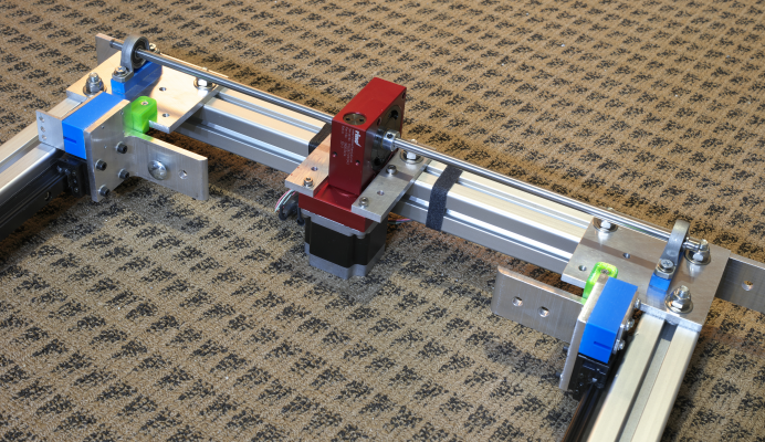
I modified the Z axis to drive two HTD 3M belts. That involved putting a longer shaft into the Rino and adding pillow blocks/bearings to the ends. I don't have the pulleys yet, so testing will have to wait a little longer. The plastic spacers under the pillow blocks will probably be replaced with metal once I have verified that they are at the proper height.
I tried using steel core GT2 belts on the XY stage and decided it was a little too stiff- steel core belts don't bend around pulleys as easily as the glass core belts. I put the glass core belts back on the machine. I may do some print tests with the steel core belt in the future.
Ultra MegaMax Dominator 3D printer: [drmrehorst.blogspot.com]
|
Re: My coreXY design is progressing to the build stage February 14, 2017 06:33PM |
Registered: 9 years ago Posts: 1,873 |
|
Re: My coreXY design is progressing to the build stage February 15, 2017 02:06AM |
Registered: 8 years ago Posts: 5,232 |
Sorry, only registered users may post in this forum.
