My coreXY design is progressing to the build stage
Posted by the_digital_dentist
|
Re: My coreXY design is progressing to the build stage February 15, 2017 07:34AM |
Registered: 11 years ago Posts: 5,780 |
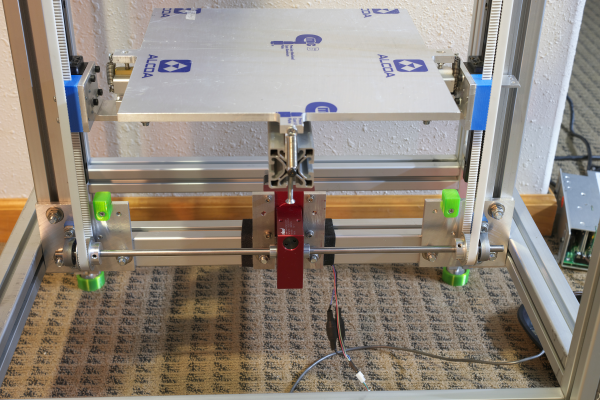
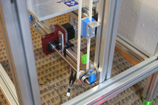
With the load that is going to be applied, flexible couplers would just act like springs. Torsion of the shaft will contribute up to about 50um (with a 4 kg print, not likely to ever happen) in vertical deflection of the bed plate (in addition to belt stretch). The pillow block bearings are "self adjusting" in that they can tilt inside their holders to align themselves with the shaft, and at this length the shaft is a little flexible (flexibility is good in this instance). There's a little slop in the attachment of all these parts, so when I installed the shaft, I did so with all the screws/bolts loose. I tightened the pillow blocks down first, letting the shaft tilt the Rino into position, then tightened it down. The most critical thing about the alignment is the height (in the photo) of the shaft above the bearing plates. The bottom half of the belt needs to be parallel to the guide rails, so the end bearing, belt clamp, and Rino shaft need to be at the right positions to keep the belt parallel. Changing the shaft height requires changing the Rino mount and the pillow block spacers. It's a lot easier to adjust the height of the end bearing and tweak the design of the printed belt clamps. When the drive pulleys arrive I'll hook up the belt and check it for parallelism and make adjustments as needed, and probably replace the plastic spacers with milled aluminum.
The drive pulleys are on that one boat from China that is carrying everything that Americans ordered during the New Year holidays.
Ultra MegaMax Dominator 3D printer: [drmrehorst.blogspot.com]
The drive pulleys are on that one boat from China that is carrying everything that Americans ordered during the New Year holidays.
Ultra MegaMax Dominator 3D printer: [drmrehorst.blogspot.com]
|
Re: My coreXY design is progressing to the build stage February 17, 2017 03:16AM |
Registered: 8 years ago Posts: 1,671 |
|
Re: My coreXY design is progressing to the build stage February 17, 2017 09:19AM |
Registered: 11 years ago Posts: 5,780 |
|
Re: My coreXY design is progressing to the build stage February 19, 2017 12:26AM |
Registered: 11 years ago Posts: 5,780 |
The 3D printing gods smiled upon me today and my pulleys arrived from China! I wasted no time in installing and testing them:
[vimeo.com]
[vimeo.com]
Belt stretch under load is about 1/3 of what it was with the original, long, serpentine belt design. I have not tested right and left sides for equal stretch.
The pulleys have 36 teeth, and I can probably go just a little faster than 20 mm/sec, but 20 appears to work reliably, so I'm going to set it as the maximum. The dimensions I used to estimate the positions of the slots in the belt clamps were spot-on, so I won't have to redesign and print those. The clamped sides of each belt loop are as parallel to the Z axis rails as I will be able to make them.
Now I need to fabricate a couple small parts for the Z=0 limit switch...
Edited 1 time(s). Last edit at 02/19/2017 07:57AM by the_digital_dentist.
Ultra MegaMax Dominator 3D printer: [drmrehorst.blogspot.com]
[vimeo.com]
[vimeo.com]
Belt stretch under load is about 1/3 of what it was with the original, long, serpentine belt design. I have not tested right and left sides for equal stretch.
The pulleys have 36 teeth, and I can probably go just a little faster than 20 mm/sec, but 20 appears to work reliably, so I'm going to set it as the maximum. The dimensions I used to estimate the positions of the slots in the belt clamps were spot-on, so I won't have to redesign and print those. The clamped sides of each belt loop are as parallel to the Z axis rails as I will be able to make them.
Now I need to fabricate a couple small parts for the Z=0 limit switch...
Edited 1 time(s). Last edit at 02/19/2017 07:57AM by the_digital_dentist.
Ultra MegaMax Dominator 3D printer: [drmrehorst.blogspot.com]
|
Re: My coreXY design is progressing to the build stage February 19, 2017 02:24AM |
Registered: 7 years ago Posts: 249 |
|
Re: My coreXY design is progressing to the build stage February 19, 2017 03:45AM |
Registered: 8 years ago Posts: 5,232 |
What was the "Meeeow" sound ~13sec. in the lifting video?
I haven't seen all the pics of this build. May I ask, if you have three point bed adjuster springs ( I'm sure you have ) and what will happen when the print is heavier on the backside. Would this relax the front spring?
Edited 1 time(s). Last edit at 02/19/2017 03:46AM by o_lampe.
I haven't seen all the pics of this build. May I ask, if you have three point bed adjuster springs ( I'm sure you have ) and what will happen when the print is heavier on the backside. Would this relax the front spring?
Edited 1 time(s). Last edit at 02/19/2017 03:46AM by o_lampe.
|
Re: My coreXY design is progressing to the build stage February 19, 2017 07:49AM |
Registered: 11 years ago Posts: 5,780 |
Quote
o_lampe
What was the "Meeeow" sound ~13sec. in the lifting video?
I haven't seen all the pics of this build. May I ask, if you have three point bed adjuster springs ( I'm sure you have ) and what will happen when the print is heavier on the backside. Would this relax the front spring?
That sound was my assistant and harshest critic, Ms. Kitty.
The bed sits on three screws (reference, pitch, and roll adjusters) and is held down on them by its own weight and springs at each screw. If the print were located off center and heavy enough, it could tilt the bed by stretching the hold-down spring at the roll adjuster (in front). I'm not too concerned- the spring at the roll adjuster is a little light, but I'll be replacing it with a much stronger one. I set the bed up this way because I wanted to eliminate any side loading on the support screws due to thermal expansion of the bed plate, and because the "normal" way of doing it would require the springs to hold up the weight of the bed and print. This way the weight is borne entirely by the screws.
The worm drive prevents the bed from dropping when power to the Z motor is lost.
Edited 2 time(s). Last edit at 02/19/2017 08:11AM by the_digital_dentist.
Ultra MegaMax Dominator 3D printer: [drmrehorst.blogspot.com]
|
Re: My coreXY design is progressing to the build stage February 19, 2017 08:31AM |
Registered: 8 years ago Posts: 5,232 |
|
Re: My coreXY design is progressing to the build stage February 19, 2017 08:46AM |
Registered: 11 years ago Posts: 5,780 |
Quote
prot0typ1cal
I like the new Z belt-worm drive set-up.
Solid, symmetrical, and simple.
What a tank !
I like this design better than the original serpentine belt. Now we'll see how it behaves when printing....
Ultra MegaMax Dominator 3D printer: [drmrehorst.blogspot.com]
|
Re: My coreXY design is progressing to the build stage February 21, 2017 02:15PM |
Registered: 11 years ago Posts: 5,780 |
Details...details...
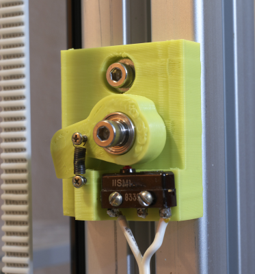
I printed a prototype of a new Z=0 switch design- it uses a lever mounted on a bearing pulled from an old HDD to push the switch. There's about a 8.5:1 ratio in the motion so the the layer thickness will be more finely adjustable than relying on the screw's threads alone. A thumbscrew will be mounted on the aluminum piece screwed to the belt clamp (blue). The small spring ensures that the lever lets the switch up when the bed moves down. There's a hole in the body of the switch mount to route the wires more neatly. The switch mount is attached to the printer's frame using a T-nut.
I have also mounted a switch to set the Z=max limit so the controller doesn't try to push the bed beyond the end of the Z axis. I'll be adding a ramp to the belt clamp to ensure that the switch has a smooth encounter.
Please forgive the poor print quality- I printed these on my CubeX machine that isn't completely dialed in yet.
Ultra MegaMax Dominator 3D printer: [drmrehorst.blogspot.com]
|
Re: My coreXY design is progressing to the build stage February 27, 2017 05:25PM |
Registered: 11 years ago Posts: 5,780 |
I'm firmly in the minor-details-that-the-machine-can't-operate-without phase.
I finished the design of the z=0 switch and posted it to Youmagine.com in case anyone is interested. It may not be exactly what you need, but you might get some useful ideas from the design.
[www.youmagine.com].
I installed the bed heater, terminal blocks, the PEI print surface, set up the thermistor using the Steinhart-Hart coefficients, and did a couple tests of the z axis homing and Zmax switch behavior.
Ultra MegaMax Dominator 3D printer: [drmrehorst.blogspot.com]
|
Re: My coreXY design is progressing to the build stage February 28, 2017 04:02AM |
Registered: 8 years ago Posts: 88 |
As I told you before, I've stolen some (lots?) ideas from your design. I am already printing because I am the other way around. Want to see something working fast, to get boost for fixing details.
The single horizontal beam for the bed, 2020 in my case, allows a little torsion, enough to allow the bed (320x320) to catch vibration from the fast moving head (3000 accel, 40 jerk, speeds up to 100mm/sec).
You can't see that on the model surface because I print in the middle of the bed, but it can be seen by eye at the edge of the plate. I didn't try to print at the edge yet, but considering that it can be seen by naked eye, I assume it is at least 0.1mm.
I am planning to add a third screw in the back to eliminate this, but not before testing a print on the edge.
|
Re: My coreXY design is progressing to the build stage February 28, 2017 08:25AM |
Registered: 11 years ago Posts: 5,780 |
I have all the motors connected to the controller, but haven't installed the Xmin switch yet- probably today- and then I can fake a print and see if there's any visible motion at the edges of the plate. I replaced 1/8" thick L brackets that connected the Z axis bearing blocks to the cross bar with 1/4" thick brackets a while ago and it stiffened things up considerably, and the 40x40 mm extrusion I am using is pretty rigid, so I think if there's any unwanted motion it will come from slop (that I can't see) in the bearing blocks, but who knows...
Edited 1 time(s). Last edit at 02/28/2017 08:31AM by the_digital_dentist.
Ultra MegaMax Dominator 3D printer: [drmrehorst.blogspot.com]
Edited 1 time(s). Last edit at 02/28/2017 08:31AM by the_digital_dentist.
Ultra MegaMax Dominator 3D printer: [drmrehorst.blogspot.com]
|
Re: My coreXY design is progressing to the build stage February 28, 2017 04:51PM |
Registered: 8 years ago Posts: 88 |
Yes, a cheaper option would be to use a stronger beam. The good thing is that it doesn't have to be extrusion. It can be anything.
Now that I've got myself a nice BF20L milling machine, I need jobs to do on it, so I'll do my beam supports in metal first (ABS cubes now, I'm using 12x3 trapezoidal screws) then I'll find a better beam.
Yes, please, do tell me if your setup dances up-down at the front/back edges.
Now that I've got myself a nice BF20L milling machine, I need jobs to do on it, so I'll do my beam supports in metal first (ABS cubes now, I'm using 12x3 trapezoidal screws) then I'll find a better beam.
Yes, please, do tell me if your setup dances up-down at the front/back edges.
|
Re: My coreXY design is progressing to the build stage March 01, 2017 11:51PM |
Registered: 11 years ago Posts: 5,780 |
Some test video of a dry run at 150 mm/sec. Acceleration is 1000 mm/s/s. I used a large enough object that the thing will actually hit 150 mm/sec when running the infill at 45 and 135 degrees driven by a single motor. I set all speeds in the slicer, including small perimeters, to 150 mm/sec.
The Z axis is operating during all this, too. It lifts on retract and of course, steps 0.2 mm for each layer.
No matter what sort of crazy stuff the extruder carriage does, I don't see the edges of the bed plate bouncing or vibrating at all.
Here's the Z=0 switch in operation I added a lever because I have found (in my other printer) that bed zero position is just too hard to control when the adjuster screw pushes the switch directly. One turn of the screw results in almost 800 um of bed displacement. Since adjustments more typically need to be on the order of 50 um at a time, it's a little hard to know just how far the bed's going to move when you turn the screw. The lever provides about an 8:1 reduction in sensitivity, so one full turn of the 32 TPI screw results in about 100 um of bed movement. It tilts on a bearing removed from a HDD that press fits into the lever. The small spring ensures that the switch opens when the bed moves down (instead of relying on the weight of the lever alone to open the switch).
Here's the Zmax switch in operation The Z axis motion stops about 1/2 mm above the bright green rubber bumper.
Edited 2 time(s). Last edit at 03/02/2017 10:42AM by the_digital_dentist.
Ultra MegaMax Dominator 3D printer: [drmrehorst.blogspot.com]
|
Re: My coreXY design is progressing to the build stage March 02, 2017 06:20AM |
Registered: 8 years ago Posts: 88 |
|
Re: My coreXY design is progressing to the build stage March 02, 2017 11:00AM |
Registered: 11 years ago Posts: 5,780 |
I still haven't installed the Xmin switch. For the test video I just edited out the G28 home command at the start of the gcode file and replaced it with a G92 command that sets the origin wherever the extruder carriage and Z axis happen to be. I also edit out any homing commands at the end of the gcode file. Before starting the "print", I manually push the extruder carriage to the home position. This keeps it from banging into the end of the X axis when it tries to home but can't find the X=0 switch (that isn't there yet).
I'm still deciding how to handle the X=0 switch. I have some big, ugly industrial optical beam parts that can do the job without using any moving cables, so I think I'll give that a try. I like minimizing wires in moving cables.
Edited 1 time(s). Last edit at 03/02/2017 12:47PM by the_digital_dentist.
Ultra MegaMax Dominator 3D printer: [drmrehorst.blogspot.com]
|
Re: My coreXY design is progressing to the build stage March 02, 2017 01:54PM |
Registered: 8 years ago Posts: 88 |
Mine is now on the left part of the X beam, fixed on X, moving in Y and it is ... ugly, at least. I will do the other way around and move the sensor on the carriage and the metal target on the X beam. I already have 3 hoses going to the carriage (one for cables, 2 for air) so it is easier to add another cable there.
|
Re: My coreXY design is progressing to the build stage March 03, 2017 01:19AM |
Registered: 8 years ago Posts: 5,232 |
|
Re: My coreXY design is progressing to the build stage March 03, 2017 07:48AM |
Registered: 11 years ago Posts: 5,780 |
I'm not sure what you mean, but we'll see how it holds up. I think that the snap action mechanism of that type of switch makes it pretty reliable, regardless of what's going on at the button -which I think is the whole point of that type of switch design- it provides consistent switching speed and contact pressure using the bistable snap action. I can redesign it for an opto interrupter easily enough, but prefer the much simpler connection and termination of the mechanical switch.
I'm going to try to fit an optical X=0 switch today- I have an industrial emitter/detector pair of direct beam, 2m range opto switch. I have to test it to make sure it's functional, then figure out the voltage divider to make sure it doesn't kill the input on the controller, then design and print mounting brackets for it.
Ultra MegaMax Dominator 3D printer: [drmrehorst.blogspot.com]
|
Re: My coreXY design is progressing to the build stage March 03, 2017 02:47PM |
Registered: 8 years ago Posts: 88 |
|
Re: My coreXY design is progressing to the build stage March 04, 2017 05:25PM |
Registered: 7 years ago Posts: 11 |
I fail to see how the Z0 switch increases accuracy. 1 turn of the screw will offset the 0-point the same amount, no matter the "gearing" you put on the switch.
Unless i missed something, you just made it so the new switch (switch + lever) needs to move deeper to trigger.
Unless you're just using the switch to get a repeatable Z0 mark and the fine-tune the first layer height in software?
Edited 2 time(s). Last edit at 03/04/2017 05:29PM by Skrogh.
Unless i missed something, you just made it so the new switch (switch + lever) needs to move deeper to trigger.
Unless you're just using the switch to get a repeatable Z0 mark and the fine-tune the first layer height in software?
Edited 2 time(s). Last edit at 03/04/2017 05:29PM by Skrogh.
|
Re: My coreXY design is progressing to the build stage March 04, 2017 06:20PM |
Registered: 11 years ago Posts: 5,780 |
The screw threads are 1/32" = 794 um per turn. The lever is approximately 8:1. Turning the screw 1 full turn will move the switch end of the lever about 100 um, so it is less sensitive to the screw rotation making it easier to make small changes in the bed zero position.
If the screw were pushing the switch directly, moving the bed position 100 um would require making just 1/8 of a turn. With the lever, moving the bed position by 100 um will require a full turn of the screw.
Ultra MegaMax Dominator 3D printer: [drmrehorst.blogspot.com]
If the screw were pushing the switch directly, moving the bed position 100 um would require making just 1/8 of a turn. With the lever, moving the bed position by 100 um will require a full turn of the screw.
Ultra MegaMax Dominator 3D printer: [drmrehorst.blogspot.com]
|
Re: My coreXY design is progressing to the build stage March 05, 2017 10:34AM |
Registered: 7 years ago Posts: 11 |
Yes moving the end of the screw ~800 um up will move the switch by 100 um, but for the switch to move back to 0, the bed (with screw) must move 800 um down again.Quote
the_digital_dentist
The screw threads are 1/32" = 794 um per turn. The lever is approximately 8:1. Turning the screw 1 full turn will move the switch end of the lever about 100 um, so it is less sensitive to the screw rotation making it easier to make small changes in the bed zero position.
A full turn of the screw will change the relative position of the end of the screw with ~800 um with respect to the bed, no matter the lever action on the switch (assuming an ideal switch).Quote
the_digital_dentist
If the screw were pushing the switch directly, moving the bed position 100 um would require making just 1/8 of a turn. With the lever, moving the bed position by 100 um will require a full turn of the screw.
I hope I am not coming off as rude, but I think you might have made a mistake with this part of the design.
|
Re: My coreXY design is progressing to the build stage March 05, 2017 11:32AM |
Registered: 11 years ago Posts: 5,780 |
Yes a full turn of the screw moves the end of the screw relative to the bed by 800 um, but at the switch it looks like 100 um, as if you had turned the screw 1/8 of a turn. It's the screw position relative to the switch that determines where z=0 is, not the end of the screw relative to the bed.
The switch has a small dead band between snapping open (when pushed) and snapping closed (when released). The lever will multiply that deadband by 8X, but I don't think it's going to be a problem. You're suggesting that if the switch doesn't close until the bed has dropped by maybe 500 um, I won't be able to print a 250 um first layer. That suggests that the firmware considers the zero point to be the Z position where the switch closes, not where it opens (wired NC). If that were true, there would be a lot of problems with different printers because people use different switches with varying amounts of hysteresis. I have posed the question to the smoothieware people to verify and will update when I hear back. In the mean time I'll try to run a few tests- I'll drop the bed in 10 um increments until the switch closes and record the value, then try "printing" a first layer within the switch's dead-band. If it closes at 500 um, I'll try to print at 250 um.
When you start a print, the first thing in the gcode is a home instruction that will initialize the coordinates by moving all three axes to their home positions including z=0. It does a relatively fast move to the zero point where the switch opens, then backs off a few mm (5mm in my config, closing the switch) and creeps slowly up on the zero position again until the switch opens. That sets the zero point. The next thing that happens, depending on your slicer, is that the bed drops a few mm (that closes the z=0 switch), then the extruder moves to the XY start point, the bed raises to print height and the print starts. So even if the print layer is smaller than the hysteresis of the switch, the print should work fine.
I just checked a couple things. When I home Z in Pronterface, the bed moves up until the switch opens, then backs off a few mm, reclosing the switch, then moves up slowly again until the switch opens, and finally drops a few (one?) mm which closes the switch. I tried just turning the screw to see how far it has to turn in order for the switch to go from open to closed and it's about 1/2 turn equivalent to about 50 um in bed movement. I don't think there's going to be any problems with the levered switch.
Edited 7 time(s). Last edit at 03/05/2017 12:41PM by the_digital_dentist.
Ultra MegaMax Dominator 3D printer: [drmrehorst.blogspot.com]
|
Re: My coreXY design is progressing to the build stage March 05, 2017 01:45PM |
Registered: 7 years ago Posts: 11 |
this is where I think you are wrong. It is the screw position relative to the bed that matters when the screw is attached on the bed side of the lever.Quote
the_digital_dentist
Yes a full turn of the screw moves the end of the screw relative to the bed by 800 um, but at the switch it looks like 100 um, as if you had turned the screw 1/8 of a turn. It's the screw position relative to the switch that determines where z=0 is, not the end of the screw relative to the bed.
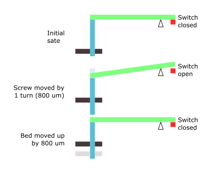
Move the screw by -800um and the switch moves -100um. Now for the bed to be level the switch needs to be at 0um, the switch must move +100um so the bed must move +800us.
I made a small illustration of the scenario:
If you don't believe me, try moving the screw-end by say 1 or 2 cm.The z0 point of the bed will not move 1/8th of that.
I am not including hysteresis in my "model", since repeatability is what is important, and the hysteresis level should be constant.
|
Re: My coreXY design is progressing to the build stage March 05, 2017 02:14PM |
Registered: 11 years ago Posts: 5,780 |
You're right. Doh! Looks like I need a redesign...
Edited 1 time(s). Last edit at 03/05/2017 02:15PM by the_digital_dentist.
Ultra MegaMax Dominator 3D printer: [drmrehorst.blogspot.com]
Edited 1 time(s). Last edit at 03/05/2017 02:15PM by the_digital_dentist.
Ultra MegaMax Dominator 3D printer: [drmrehorst.blogspot.com]
|
Re: My coreXY design is progressing to the build stage March 06, 2017 02:58AM |
Registered: 7 years ago Posts: 11 |
It might be a tad overkill, but you could use a micrometer.
The pitch might not be a whole lot finer, but the larger grip will allow fine adjustment. You get an indicator as well. (so you're not just turning a screw by approximately 1/2 turn, but can actually see exactly by how much). Most of them have backlash compensation and a lock as well.
The pitch might not be a whole lot finer, but the larger grip will allow fine adjustment. You get an indicator as well. (so you're not just turning a screw by approximately 1/2 turn, but can actually see exactly by how much). Most of them have backlash compensation and a lock as well.
|
Re: My coreXY design is progressing to the build stage March 06, 2017 04:20AM |
Registered: 10 years ago Posts: 38 |
The micrometer might be a good idea. It did get me to thinking about some products I am familiar with. They come from a company called Thor Labs. They are based in the US. Here is a link "https://www.thorlabs.com/navigation.cfm?guide_id=131". Sorry I was not able to create a click able link. Look for the image containing 3/16-100 actuators. They have adjustment screws as well as threaded bushings with nuts.
|
Re: My coreXY design is progressing to the build stage March 06, 2017 10:40AM |
Registered: 7 years ago Posts: 11 |
ThorLabs makes some really neat stuff. I've only played around with their micrometers (which is were I got the idea - we used them to test some inductive distance sensors at a class). I didn't know they make so much other nice stuff. They have some 0.25mm pitch screws at a reasonable 4-10€.
Sorry, only registered users may post in this forum.

 My cat always tries to chase the effector of my delta. I'm glad it is enclosed

