My coreXY design is progressing to the build stage
Posted by the_digital_dentist
|
Re: My coreXY design is progressing to the build stage April 05, 2018 12:15PM |
Registered: 11 years ago Posts: 5,780 |
I was thinking that the gears and bearings are fine, they just need to be mounted in aluminum instead of plastic. I can probably come up with some other way to mount the whole thing, too.
Ultra MegaMax Dominator 3D printer: [drmrehorst.blogspot.com]
Ultra MegaMax Dominator 3D printer: [drmrehorst.blogspot.com]
|
Re: My coreXY design is progressing to the build stage April 05, 2018 12:29PM |
Registered: 6 years ago Posts: 68 |
Best would to take aero like lid and mount it to aluminium base. Lid would eliminate all wobling from massive heatsink. And if all this could be attached separately from motor.
I have tevo extruder and there is different axle to idlerarm so the motor could be easily removed if extruder base have own screws...
I have tevo extruder and there is different axle to idlerarm so the motor could be easily removed if extruder base have own screws...
|
Re: My coreXY design is progressing to the build stage April 05, 2018 08:48PM |
Registered: 11 years ago Posts: 5,780 |
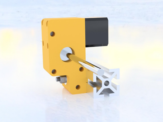
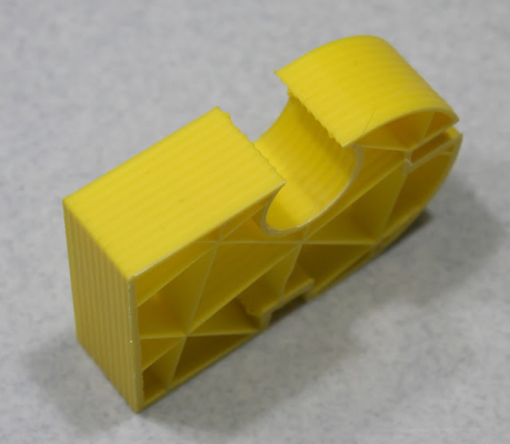
I have been tweaking the design for the gearbox in Fusion360 and I think I have it in a form that is optimally useful. It's designed for 1.5" or 40 mm square t-slot, but can easily be modified for 1" or 25 mm or 30 mm square material with a few minor edits.
The size is 110 mm long by 54 mm high x 44.7 mm wide (about 2.5 mm wider than the NEMA-17 motor).
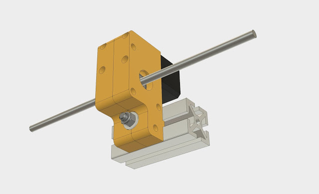
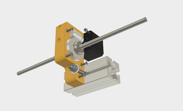
It is printed in 2 pieces using a total of just over 100g of ABS as seen here:
It uses 4x M3 x 16 mm screws to secure the motor, and 4x #6 (yeah, I know, mixed units suck, but #MAGA!) x 1" long plastic thread rolling screws, 1x 5/16"-18 carriage bolt (or 8mm carriage bolt), washer, and nylock nut, 2x 8mm nylon washers, 2x RF2280HH (same size as F608zz) bearings, an 8mm shaft, and 40:1 worm gears purchased via ali-express.
I positioned the gear axles 29.35 mm apart and get just a hair of rotational play in the shaft that ensures the mechanism doesn't bind. The play won't matter in a low friction Z axis because gravity will keep it loaded in one direction at all times.
The shaft is 19.5 mm away from one face of the t-slot and 27 mm away from the other. It can be mounted in any of 4 positions depending on your printer's frame design and where you want the motor to be (inside or outside enclosure, etc.) and/or belts to run.
Dimensions here: [a360.co]
I'm looking at a design that mounts it sideways to turn a single pulley in case anyone wants to use a single belt for the Y axis, like this: [drmrehorst.blogspot.com]
This design is a bit different from what I used for the UMMD version because I had to design the mount for drop-in replacement for the Rino in UMMD.
Any feedback on the mounting method or the position of the mount is welcome...
Edited 3 time(s). Last edit at 04/05/2018 09:01PM by the_digital_dentist.
Ultra MegaMax Dominator 3D printer: [drmrehorst.blogspot.com]
|
Re: My coreXY design is progressing to the build stage April 06, 2018 12:41AM |
Registered: 11 years ago Posts: 5,780 |
Well OK then! I took a closer look at it and realized it was not going to be the huge effort to install in UMMD that I had thought, so I installed it, tweaked the config file and here is the first test:
Printed gearbox load test, 4 kg @ 10 mm/sec
More testing will be done this weekend...
Ultra MegaMax Dominator 3D printer: [drmrehorst.blogspot.com]
Printed gearbox load test, 4 kg @ 10 mm/sec
More testing will be done this weekend...
Ultra MegaMax Dominator 3D printer: [drmrehorst.blogspot.com]
|
Re: My coreXY design is progressing to the build stage April 06, 2018 07:21PM |
Registered: 7 years ago Posts: 128 |
@the_digital_dentist, the unit in your drawing looks different than the one you mounted to UMMD...  Is the weight restriction that yor're experiencing related to the stepper you're using or the design?
The only problem I see with mounting the stepper above the unit is with space in the Z Axis. With the unit parallel to the build plate I think you'll get more room...
Looking forward to playing with your drawings...
ampapa,
 Is the weight restriction that yor're experiencing related to the stepper you're using or the design?
The only problem I see with mounting the stepper above the unit is with space in the Z Axis. With the unit parallel to the build plate I think you'll get more room...
Looking forward to playing with your drawings...
ampapa,
|
Re: My coreXY design is progressing to the build stage April 06, 2018 08:11PM |
Registered: 11 years ago Posts: 5,780 |
The one I installed in UMMD was designed as an almost-drop-in replacement for the Rino because I didn't want to have to do a lot of metal work to fit it.
In the other design the whole thing can be rotated to any of 4 positions to put the motor where it is most convenient. You can't really put the motor and t-slot next to each other because there would be no way to mount the gearbox on the t-slot that way.
Ultra MegaMax Dominator 3D printer: [drmrehorst.blogspot.com]
|
Re: My coreXY design is progressing to the build stage April 06, 2018 09:32PM |
Registered: 11 years ago Posts: 5,780 |
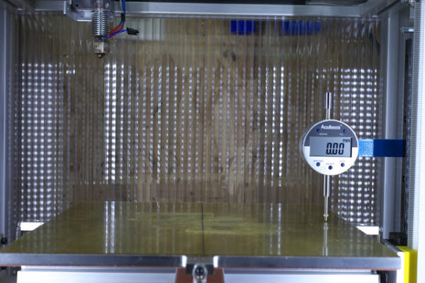
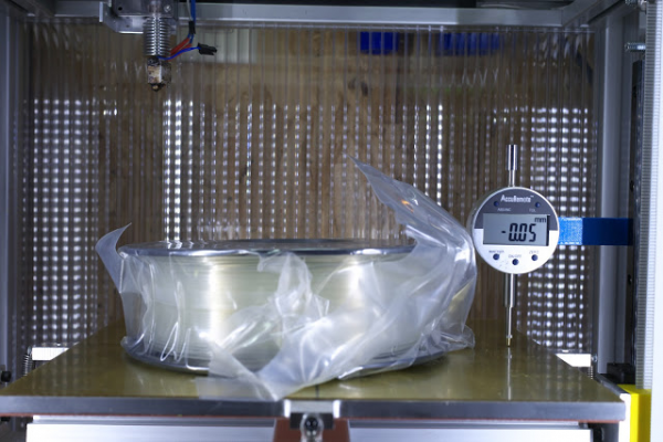
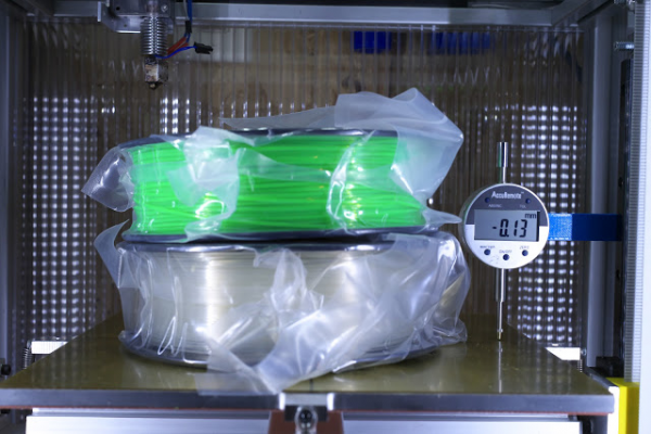
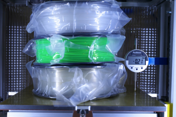
Belt stretch:
In the last image the load is 3.75 kg, stretch is 0.21 mm -> so about 56 um/kg
I also did some testing by stepping the bed up and down in 10mm and 1 mm steps.
The accuracy spec on the gauge is +/- 0.02 mm, and precision is +/- 0.01 mm
See: [vimeo.com]
Ultra MegaMax Dominator 3D printer: [drmrehorst.blogspot.com]
|
Re: My coreXY design is progressing to the build stage April 08, 2018 01:29AM |
Registered: 11 years ago Posts: 5,780 |
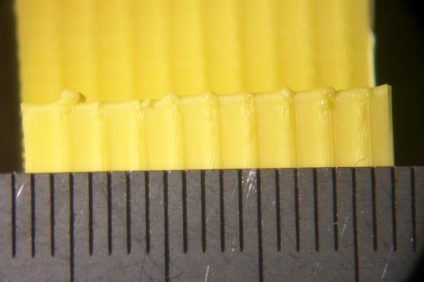
I fixed the extruder problem and ran a test print. It doesn't look good.
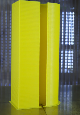
The print was made in 100 um layers (10 full steps). The 2mm interval in the Z ribbing is caused by a problem with the worm gear. The gear makes one rev every 2 mm and ribs repeat at 2 mm intervals. I don't think there's any fix that can be applied. It might be less of a problem when printing in thicker layers.
Oh well, I'll put the Rino back into the machine tomorrow.
Ultra MegaMax Dominator 3D printer: [drmrehorst.blogspot.com]
|
Re: My coreXY design is progressing to the build stage April 08, 2018 02:02AM |
Registered: 8 years ago Posts: 5,232 |
|
Re: My coreXY design is progressing to the build stage April 08, 2018 07:27AM |
Registered: 7 years ago Posts: 128 |
|
Re: My coreXY design is progressing to the build stage April 08, 2018 09:58AM |
Registered: 11 years ago Posts: 5,780 |
It's not wobble, it's ribbing. Wobble implies instability in the lateral position of the bed relative to the extruder, causing layer registration to shift, so there is a bulge on one side of the part and a dent on the opposite side. In this case, the layers aren't shifting, they are printing thinner that they are supposed to and the plastic is getting squished out from under the nozzle creating a bulge that goes all around the part (and in the infill ribs).
What is happening is that the gear probably has some sort of discontinuity (a divot) at one spot (or the bore is off center). When that spot rotates into contact with the disc gear the disc gear doesn't turn as much as it should and that translates to layers getting thinner than they should be. That squishes out the plastic in a few layers and creates a rib in the print until the divot has rotated out of contact with the disc gear. The ribs are spaced every 2 mm because the worm gear rotates once for every 2mm of Z axis movement. If I let the print continue for 80+ mm, we'd be able to see what sort of quality problems the disc gear has because errors in that gear will repeat every 80 mm in Z.
The discontinuity could be localized to one spot and since only one tooth of the worm gear contacts the disc gear, moving the worm gear along the motor shaft might bring a different, better (or worse) tooth into contact with the disc gear. The only way to test it is to take the whole thing apart, move the worm gear a little, put it all back together and test again. I don't have the patience for all that.
This gearing works fine if you need lots of torque and stable position when the motor power is cut, but it isn't accurate enough for a 3D printer Z axis, at least not in one that is expected to print in thin layers. The gear quality is just not good enough. These gears are sintered. I suspect that high quality machined gears are needed for the precision and accuracy required in a printer's Z axis. The Rino has those.
I'll run two more tests- step the Z axis in 0.1 mm intervals with the gauge attached, and another test print with 0.25 mm layers to see how much it improves, but I'm not expecting it to be great.
Then I'm going to put the Rino back into the machine...
Edited 1 time(s). Last edit at 04/08/2018 10:29AM by the_digital_dentist.
Ultra MegaMax Dominator 3D printer: [drmrehorst.blogspot.com]
|
Re: My coreXY design is progressing to the build stage April 08, 2018 11:14AM |
Registered: 7 years ago Posts: 128 |
Ah, now that makes sense thanks for the additional insight.
I'm curious now then what the cost is for some precision ground gears...?? It has to be cheaper than the OnDrive unit itself.
Precision gears
Seems like that is whee the cost of the unit should be spent..
ampapa,
I'm curious now then what the cost is for some precision ground gears...?? It has to be cheaper than the OnDrive unit itself.
Precision gears
Seems like that is whee the cost of the unit should be spent..
ampapa,
|
Re: My coreXY design is progressing to the build stage April 08, 2018 12:21PM |
Registered: 11 years ago Posts: 5,780 |
The Rino I bought used via ebay was $116 including shipping (IRIC). Brand new they sell for over $750. Precision gears are not cheap.
Compare the photos of the OnDrives gears to the ones I used:
You can see the quality difference...
Edited 2 time(s). Last edit at 04/08/2018 01:42PM by the_digital_dentist.
Ultra MegaMax Dominator 3D printer: [drmrehorst.blogspot.com]
Compare the photos of the OnDrives gears to the ones I used:
You can see the quality difference...
Edited 2 time(s). Last edit at 04/08/2018 01:42PM by the_digital_dentist.
Ultra MegaMax Dominator 3D printer: [drmrehorst.blogspot.com]
|
Re: My coreXY design is progressing to the build stage April 08, 2018 03:18PM |
Registered: 11 years ago Posts: 335 |
|
Re: My coreXY design is progressing to the build stage April 09, 2018 03:02PM |
Registered: 7 years ago Posts: 128 |
|
Re: My coreXY design is progressing to the build stage April 09, 2018 03:47PM |
Registered: 11 years ago Posts: 335 |
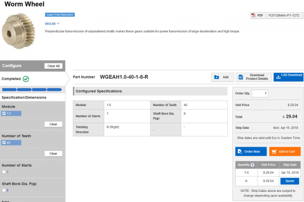
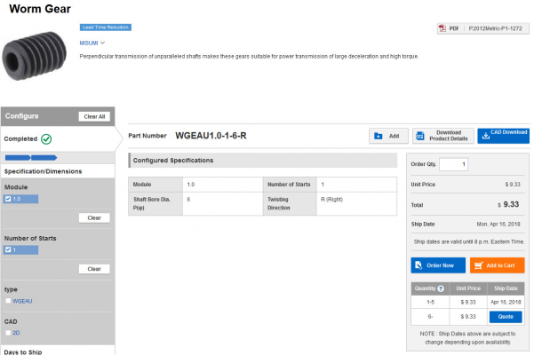
[us.misumi-ec.com]
[us.misumi-ec.com]
They carry other brands of worm gears as well, but I tend to avoid third party products on Misumi since the lead times are longer and the documentation is less detailed.
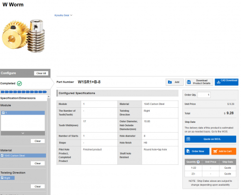
For example [us.misumi-ec.com] looks plausible but has no description.
[us.misumi-ec.com]
They carry other brands of worm gears as well, but I tend to avoid third party products on Misumi since the lead times are longer and the documentation is less detailed.
For example [us.misumi-ec.com] looks plausible but has no description.
|
Re: My coreXY design is progressing to the build stage April 09, 2018 05:47PM |
Registered: 11 years ago Posts: 5,780 |
I ran a couple more tests. I did a 165 mm tall print in 0.25 mm layers and it looks a little better but it's not going to win any prizes.
I can't see any repeating defects at 80 mm intervals, just the 2 mm ribbing.
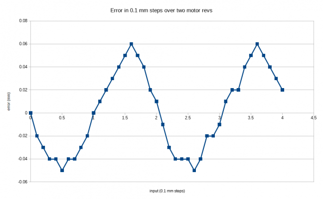
I also stepped the bed through 4 mm (2 revs of the worm gear) in 0.1 mm steps and plotted the error:
I don't know if the gear surface is the problem or if the bore hole in the worm gear is off center, but either way, it isn't going to work with these gears.
Ultra MegaMax Dominator 3D printer: [drmrehorst.blogspot.com]
|
Re: My coreXY design is progressing to the build stage April 09, 2018 09:47PM |
Registered: 7 years ago Posts: 128 |
I think the concept @the_digital_dentist was trying to accomplish was an affordable worm gear solution, at $190 for a gearbox I think I'll use one of my Rino's..
Now at $38+shp it gets back into reasonable...
@the_digtial_dentist, it certainly is a repeatable issue...
ampapa,
|
Re: My coreXY design is progressing to the build stage April 09, 2018 11:16PM |
Registered: 11 years ago Posts: 5,780 |
That worm gear has a 6 mm bore, so you'll either need an adapter for NEMA_17's 5mm shaft or you'll need to use a NEMA-23 motor with a 6 mm shaft. "Normal" NEMA-23 motors have a 6.35 mm (1/4") shaft.
I chose the gears I did because the sizes and gear ratio were right...
Edited 1 time(s). Last edit at 04/09/2018 11:21PM by the_digital_dentist.
Ultra MegaMax Dominator 3D printer: [drmrehorst.blogspot.com]
I chose the gears I did because the sizes and gear ratio were right...
Edited 1 time(s). Last edit at 04/09/2018 11:21PM by the_digital_dentist.
Ultra MegaMax Dominator 3D printer: [drmrehorst.blogspot.com]
|
Re: My coreXY design is progressing to the build stage April 10, 2018 02:14AM |
Registered: 6 years ago Posts: 1,007 |
|
Re: My coreXY design is progressing to the build stage April 10, 2018 02:27AM |
Registered: 8 years ago Posts: 5,232 |
|
Re: My coreXY design is progressing to the build stage April 10, 2018 06:47AM |
Registered: 7 years ago Posts: 128 |
|
Re: My coreXY design is progressing to the build stage April 11, 2018 01:52AM |
Registered: 6 years ago Posts: 1,007 |
Just a guess; if worm gear and/or wheel gear are not properly aligned (due to the mounting or gear poor quality ), resulting in a hard spot, the rotor could move axially (it is under spring tension and can move slightly). Past the hard spot , the rotor will move back to its normal position.
"A comical prototype doesn't mean a dumb idea is possible" (Thunderf00t)
"A comical prototype doesn't mean a dumb idea is possible" (Thunderf00t)
|
Re: My coreXY design is progressing to the build stage April 23, 2018 08:15PM |
Registered: 11 years ago Posts: 5,780 |
New project: UMMD is getting a Duet Ethernet board and Panel Due 7i touch screen...
Blog posts here and here so far.
More to come.
Splash Screen
Ultra MegaMax Dominator 3D printer: [drmrehorst.blogspot.com]
Blog posts here and here so far.
More to come.
Splash Screen
Ultra MegaMax Dominator 3D printer: [drmrehorst.blogspot.com]
|
Re: My coreXY design is progressing to the build stage April 25, 2018 12:07PM |
Registered: 10 years ago Posts: 651 |
Hey the_digital_dentist, I was wondering if you thought about designing/printing a more diy/cheaper version of the cooling setup you use just as you did with the Rhino. I know you use the fan from a cpap machine. I saw this and thought it might be of interest. https://www.youtube.com/watch?v=DrlVLhc6tOE
|
Re: My coreXY design is progressing to the build stage April 25, 2018 01:03PM |
Registered: 11 years ago Posts: 5,780 |
That's interesting. The thing that would concern me most is balancing the impeller. The motor he used is going to be limited in speed, but probably fast enough for the desired airflow, and the brushes are going to wear out, and it probably sounds like a vacuum cleaner. It wouldn't be too hard to make something like the blower I used (it's optimized to move air quietly- may as well copy a design that works), and I'd use a brushless motor for long life and quiet operation- maybe a motor from a HDD would work. 5400 or 7200 RPM should be enough to get the needed air volume. Hmmmm.
Ultra MegaMax Dominator 3D printer: [drmrehorst.blogspot.com]
Ultra MegaMax Dominator 3D printer: [drmrehorst.blogspot.com]
|
Re: My coreXY design is progressing to the build stage April 25, 2018 09:25PM |
Registered: 11 years ago Posts: 5,780 |
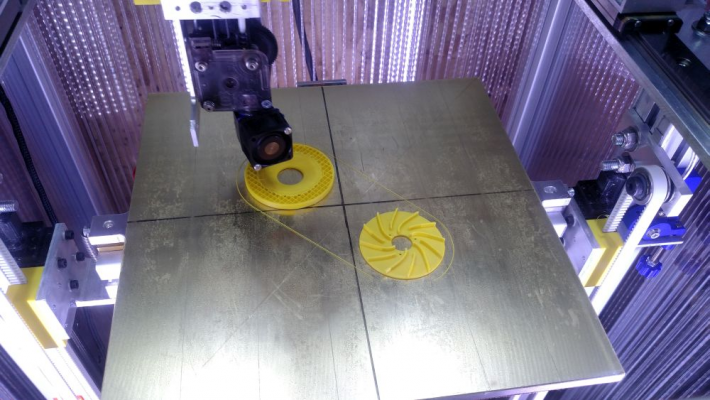
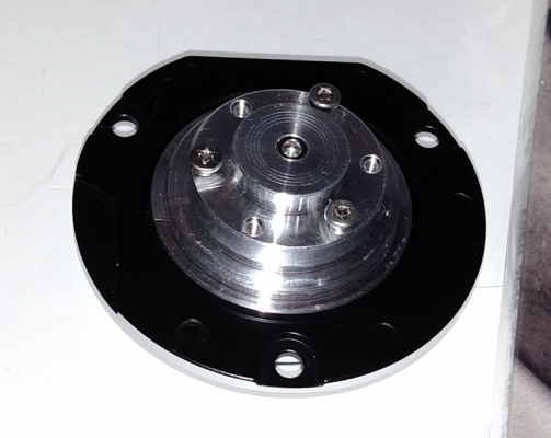
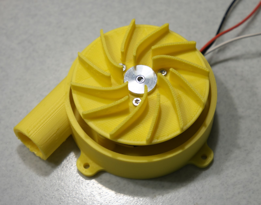
We'll know soon enough... I copied the basic format of the CPAP blower, made the impeller 60 mm in diameter, and designed it to fit a HDD motor, which most everyone can get for free. It will still need a BLDC driver, but they're pretty cheap.
This is the motor:
Edited 2 time(s). Last edit at 04/25/2018 09:32PM by the_digital_dentist.
Ultra MegaMax Dominator 3D printer: [drmrehorst.blogspot.com]
|
Re: My coreXY design is progressing to the build stage April 26, 2018 12:56PM |
Registered: 6 years ago Posts: 60 |
|
Re: My coreXY design is progressing to the build stage April 26, 2018 02:16PM |
Registered: 11 years ago Posts: 5,780 |
It works pretty well, I think. I was a little surprised that it didn't destroy itself when I spun it up to full speed. It seems to move an adequate amount of air.
Blog post here.
I'll be doing some more work on the housing design...
Ultra MegaMax Dominator 3D printer: [drmrehorst.blogspot.com]
Blog post here.
I'll be doing some more work on the housing design...
Ultra MegaMax Dominator 3D printer: [drmrehorst.blogspot.com]
|
Re: My coreXY design is progressing to the build stage April 27, 2018 02:38AM |
Registered: 8 years ago Posts: 5,232 |
Sorry, only registered users may post in this forum.
