NEW CoreXY Design
Posted by MatthewHall
|
NEW CoreXY Design May 09, 2016 08:23PM |
Registered: 8 years ago Posts: 120 |
Hey guys.
Lately I've been working on a new CoreXY 3d printer. Here is my story of development.
My first expo into 3d printing was ordering a Prusa i3 kit from Replikeo in Hong Kong. Not a bad idea, I though...except they are in Hong Kong and I am in Ohio. To far away, especially since their kit was filth and I returned and lost $90. However, that was the best 90 i've spent in my life because now I know so much more than I knew about 3d printing as a whole. I have access now to six 3d printers at my school, so I figured I had better try my hand at designing a new, better 3d printer. I have been through 4 iterations of this design and will order parts in a couple weeks.
I'm calling my printer the "Mobius" because I like the mathematical concept of that sort of thing. Having built a Prusa, I don't like the thing in the Y axis with bed travel, I believe it makes the footprint of the machine to large. The machine then has to be at least twice as large in the Y axis as the build volume. My printer is 420 mm both directions in the base with a 285 mm square bed. I am using 2020 and 2040 extrusions from Misuimi, which I can get pretty cheap here in the USA. Budget is also a concern, because I am in high school and don't have that much cash to my disposal. My printer right now costs around $300 (excluding shipping). I think that's satisfactory being that the Replikeo kit cost me $400 and this is 1.5 times the build volume.
My design has no belt cross in the CoreXY system, uses lead screws in the Z axis, has all the GT2 belts running inside the aluminum extrusions, uses 3d printed linear motion, and has everything contained inside a 6mm birch plywood frame except two Nema17 steppers.
EDIT: pictures of printer CAD
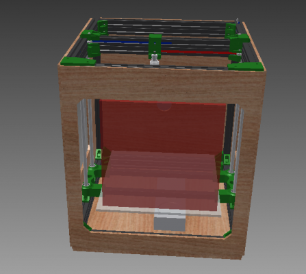
Here is a good shot of the main box:
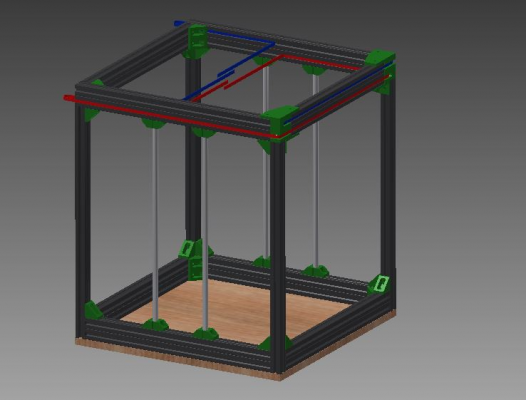
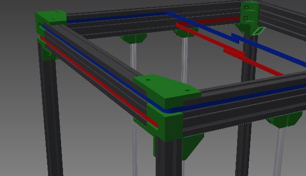
And here is the frame design:
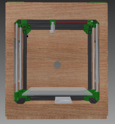
Front:
And top:
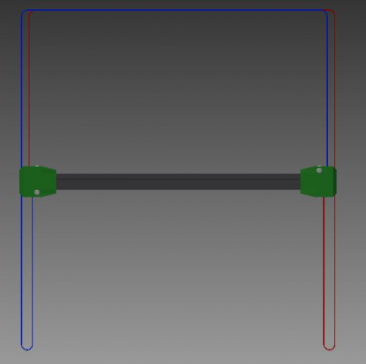
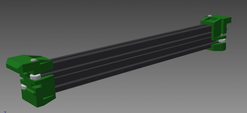
Now the important part, the gantry.
That's what I meant about the belts running through the 2040.
Pretty good for $300.
Please comment, I want to do this right (unlike Replikeo)
Thanks
Edited 2 time(s). Last edit at 05/11/2016 07:45AM by MatthewHall.
|
Re: My CoreXY Design May 09, 2016 09:03PM |
Registered: 11 years ago Posts: 5,780 |
|
Anonymous User
Re: My CoreXY Design May 09, 2016 11:34PM |
|
Re: My CoreXY Design May 10, 2016 01:43PM |
Registered: 8 years ago Posts: 120 |
|
Re: NEW CoreXY Design May 12, 2016 10:12AM |
Registered: 8 years ago Posts: 776 |
Quote
MatthewHall
My design has no belt cross in the CoreXY system, uses lead screws in the Z axis, has all the GT2 belts running inside the aluminum extrusions, uses 3d printed linear motion, and has everything contained inside a 6mm birch plywood frame except two Nema17 steppers.
Pretty good for $300.
Please comment, I want to do this right (unlike Replikeo)

hi matthew, nice idea to use wood. i'm going reaally cheap - using hardboard. works really well, it just surprises people that hardboard has significant shear-strength.
pleaase use these on the corexy:
[www.motedis.com]
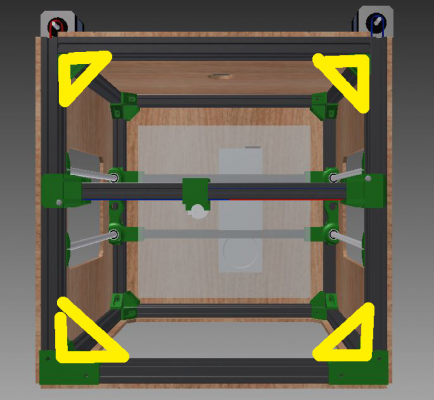
don't be tempted to get the 20x20 brackets, use the full 20x40. put 4 of those, one into each corner, of the corexy 4 extrusions.
as you have birchwood in all 5 other faces, that will give you amazing structural rigidity, *except* for those 4 corexy corners. imagine you receive a parcel, in a cardboard box, it's really rigid, right? now you open up the box *only* at the top... and it goes completely floppy, amazing huh? and that's what you've got - a floppy cardboard box
 put in 4 brackets one in each corner and you'll have an amazingly-stiff frame.
Edited 1 time(s). Last edit at 05/12/2016 10:13AM by lkcl.
|
Re: NEW CoreXY Design May 12, 2016 10:16AM |
Registered: 8 years ago Posts: 776 |
|
Re: NEW CoreXY Design May 12, 2016 02:14PM |
Registered: 10 years ago Posts: 651 |
Quote
lkcl
...in a cardboard box
That would be a valid comparison if all he were using for the frame were a thin wooden box. He's using properly sized, and connected extrusions. Plus unlike our designs (my portable design too), he has proper bracing across the top. Those plastic corner brackets where the idlers go could be less than ideal for rigidity though.
If I were going for that design, I'd go with 20x60 or 20x80 for the back and sides of the top frame. That way you could at least have metal on metal contact at those front corners.
Then for the front section where the belts cross over into the inside of the frame, I'd set it up exactly as you have it with the corner brackets, but put another piece of 20x40 below them to connect metal to metal.
Even without those changes, You'll be ok, without the huge corner brackets.
|
Re: NEW CoreXY Design May 12, 2016 09:23PM |
Registered: 8 years ago Posts: 120 |
Hi, I'm just wondering if it would be beneficial to tap the 2040 extrusions on the top by the motors. It might avoid the need for larger brackets, as I want to keep the build volume as big as possible.
Like this:
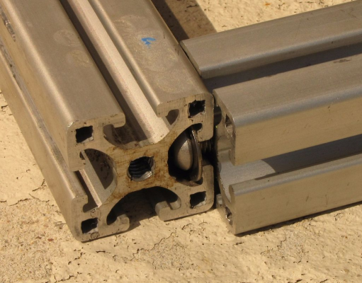
Like this:
|
Re: NEW CoreXY Design May 15, 2016 07:54AM |
Registered: 8 years ago Posts: 776 |
Quote
MatthewHall
Hi, I'm just wondering if it would be beneficial to tap the 2040 extrusions on the top by the motors. It might avoid the need for larger brackets, as I want to keep the build volume as big as possible.
Like this:
yes - perfect! good idea. that way you wouldn't need to replace the top plastic corner-parts with metal, and, also, you wouldn't need to make any other changes. remember, for this trick to work, you have to (a) have dead-flat extrusion at the end (b) drill a hole through the other piece so you have an access hole to get the allen key in. it does however mean that, added to the build tools, is a "power drill preferably bench-mounted" and "metal drill-bit". some people (such as myself, and Alex_F for the FuseBox) have added "Must not require specialised or power tools in order to build" to the Build Requirements if you are inviting other people to make this. up to you, matthew!
|
Re: NEW CoreXY Design May 15, 2016 08:09AM |
Registered: 8 years ago Posts: 776 |
Quote
FA-MAS
Quote
lkcl
...in a cardboard box
That would be a valid comparison if all he were using for the frame were a thin wooden box.
wood is elastic, therefore it doesn't matter how much you use (unless it's 8in thick), it's going to flex. a cardboard box is a very good (simple, cheap, easy, quick) way to illustrate the issue i'm communicating.
Quote
He's using properly sized, and connected extrusions. Plus unlike our designs (my portable design too), he has proper bracing across the top.
it's plastic, which is elastic... therefore automatically it's not.
Quote
Those plastic corner brackets where the idlers go could be less than ideal for rigidity though.
exactly. not sure what you're referring to, here, FA-MAS. first you say there's proper bracing, which appears to contradict what i said, then you say there are plastic corner brackets which are less than ideal, which agrees with what i said.
if you're referring to the middle (parallel) part that goes across the top, i believe that's identified as a rail-based x-carriage support, *not* a brace. if it was a brace it would need to go diagonally... which you can't do across the top because the corexy parts are in the way.
Quote
If I were going for that design, I'd go with 20x60 or 20x80 for the back and sides of the top frame. That way you could at least have metal on metal contact at those front corners.
metal-to-metal doesn't help if it can still rotate (about either edge, like you would move a really heavy piece of furniture by walking it on alternate corners) because you used plastic to attach the parts: plastic simply has too much elasticity. you *musn't* rely on plastic for rotation or shear strength, it's really that simple. if you use plastic you end up with a large lever effect (in this case 60 or 80mm onto 400mm, so a force multiplier effect of 5:1 or 6:1) which would *crack* the plastic if you put even the slightest bit too much force on it - and it really wouldn't take much.
the wood's perfect, there's not too much in the way of holes to weaken the effectiveness of the wood's bracing / rigidity effect (i.e. if the holes were any larger i'd be concerned). the idea matthew found of doing that drilling-then allen key bolts is a good one that will have the desired end-result.
|
Re: NEW CoreXY Design May 15, 2016 04:41PM |
Registered: 8 years ago Posts: 776 |
matthew, it looks like you found digital_dentist's post where he does the drilling, i'm cross-referencing for others so that they see the other photo and description [forums.reprap.org]
|
Re: NEW CoreXY Design May 16, 2016 02:42PM |
Registered: 10 years ago Posts: 651 |
Quote
lkcl
wood is elastic, therefore it doesn't matter how much you use (unless it's 8in thick), it's going to flex. a cardboard box is a very good (simple, cheap, easy, quick) way to illustrate the issue i'm communicating.
I was pointing out that you can't draw a conclusion about the rigidity of his frame by comparing just a wooden box (his) to a cardboard box. He has an entire supporting structure made from the extrusion. A more apt comparison would be if you put a wooden frame in that cardboard box. While I agree that the open cardboard box is a good way to illustrate the types of distortion of the frame you may get, I don't believe it scales to his design.
Quote
lkcl
He's using properly sized, and connected extrusions. Plus unlike our designs (my portable design too), he has proper bracing across the top.
...
exactly. not sure what you're referring to, here, FA-MAS. first you say there's proper bracing, which appears to contradict what i said, then you say there are plastic corner brackets which are less than ideal, which agrees with what i said.
You got me. I should have said MOSTLY properly connected extrusions. AKA, he's using the connection method shown by digital_dentist's picture in MOST of his corners with the exception of the the 2 at front of the CoreXY (opposite the motors) where the belts pass pass over the idlers and through to the inner of the CoreXY. What I was pointing out that those 2 joints could be less than ideal. If you look at the drawings, the plastic in the other corners (little triangle brackets) are not the primary connection and actually probably could be done without.
Quote
lkcl
if you're referring to the middle (parallel) part that goes across the top, i believe that's identified as a rail-based x-carriage support, *not* a brace. if it was a brace it would need to go diagonally... which you can't do across the top because the corexy parts are in the way.
I'm not, hope my description above cleared that up a bit.
Quote
lkcl
metal-to-metal doesn't help if it can still rotate (about either edge, like you would move a really heavy piece of furniture by walking it on alternate corners) because you used plastic to attach the parts: plastic simply has too much elasticity. you *musn't* rely on plastic for rotation or shear strength, it's really that simple. if you use plastic you end up with a large lever effect (in this case 60 or 80mm onto 400mm, so a force multiplier effect of 5:1 or 6:1) which would *crack* the plastic if you put even the slightest bit too much force on it - and it really wouldn't take much.
I was pointing out a method to not use plastic as the sole support in those corners. Which I said 20x60 or 20x80. Probably should have just stuck to 20x80. Imagine his current design then extend the top frame down another 40 mm, there would be 40mm overlap at each corner and 2 of the holes could be end tapped and connected to the adjoining extrusion. 1 connection point and it pivots, add a second and it doesn't.
Edited 1 time(s). Last edit at 05/16/2016 03:23PM by FA-MAS.
Sorry, only registered users may post in this forum.
