New COREXY Design loosely based on Vulcanus Max v1.1
Posted by thetekguy
|
New COREXY Design loosely based on Vulcanus Max v1.1 May 11, 2016 11:01PM |
Registered: 9 years ago Posts: 2 |
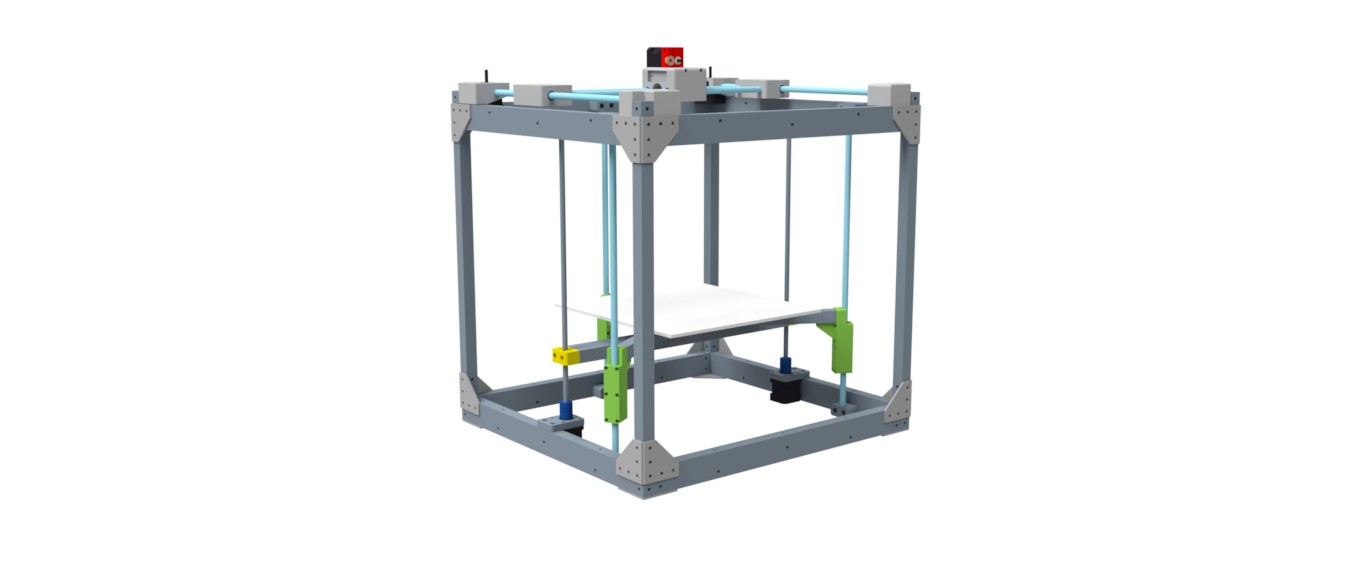
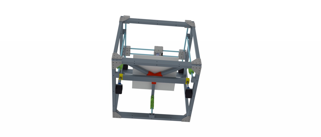
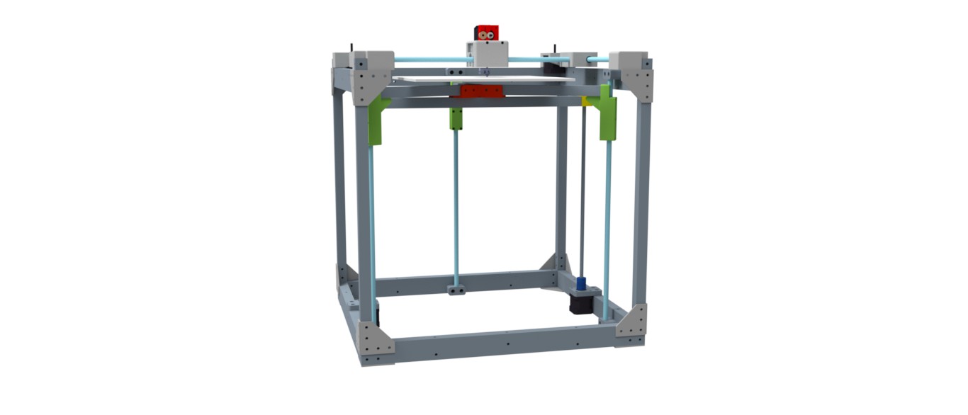
Hi all- this is my first COREXY design from scratch, based on Vulcanus Max v1.1 with frame and z carriage redesign. I used 10mm smooth rod and dual LM10UU for all x, y, and z axis carriages, and dual z lift with 8mm trapezoidal leadscrews on flexible couplers for z lift with other end of leadscrew unsupported. The bed is on a three point 2020 support 120 degrees per support, so can accommodate any bed size/dimension up to 300 x 300 mm by simply moving the bed supports on the 2020 rail. Frame is 2040 500 mm/460 mm for horizontals, and 2020 500 mm for verticals (trying to eliminate cuts as much as possible). Only thing not shown are the GT2 belts and idlers for X and Y axes. Complete design is posted to Onshape- search for Vulcanus Max 1.1 Remixed. I am assembling / test fitting now. 90% of parts are printed and test fitted. Primary goal was to maximize print volume using 500 mm extrusions, unenclosed frame (to print PLA and PETG), and heated bed. I will be adding a 3.5W laser to the x carriage to complement the single extruder. Would love your thought on potential problems / suggestions for improvement. Thanks all!
|
Re: New COREXY Design loosely based on Vulcanus Max v1.1 May 12, 2016 10:02AM |
Registered: 8 years ago Posts: 776 |
Quote
thetekguy
Hi all- this is my first COREXY design from scratch, based on Vulcanus Max v1.1 with frame and z carriage redesign. I used 10mm smooth rod and dual LM10UU for all x, y, and z axis carriages, and dual z lift with 8mm trapezoidal leadscrews on flexible couplers for z lift with other end of leadscrew unsupported. The bed is on a three point 2020 support 120 degrees per support, so can accommodate any bed size/dimension up to 300 x 300 mm by simply moving the bed supports on the 2020 rail. Frame is 2040 500 mm/460 mm for horizontals, and 2020 500 mm for verticals (trying to eliminate cuts as much as possible). Only thing not shown are the GT2 belts and idlers for X and Y axes. Complete design is posted to Onshape- search for Vulcanus Max 1.1 Remixed. I am assembling / test fitting now. 90% of parts are printed and test fitted. Primary goal was to maximize print volume using 500 mm extrusions, unenclosed frame (to print PLA and PETG), and heated bed. I will be adding a 3.5W laser to the x carriage to complement the single extruder. Would love your thought on potential problems / suggestions for improvement. Thanks all!
looks great. so sorry, have RSI now, lost the reply, let me do summary. replace all plates with these [www.motedis.com] i do mean all of them. difference is astounding. second, swap z-rods for z-screws and z-screws for z-rods. so 3 lead screws and 2 rods, not 2 screws and 3 rods. bed will be rock solid then. put lead screws in exact places where rods currently are. put rods in exact places where lead screws currently are.
if you want to test why you should consider the above, do these:
print plastic. don't let it cool down. pull it hard to try to take it off. if bed moves (and it will), you have identified a problem.
put feet through frame. bend down, take top corexy with both hands. now twist (like unscrewing bottle). if frame moves (even the slightest bit), you have identified a problem.
both these will affect print quality. sort them, you will have not just a great printer, you'll have an awesome printer.
|
Re: New COREXY Design loosely based on Vulcanus Max v1.1 May 12, 2016 10:39AM |
Registered: 9 years ago Posts: 83 |
Quote
lkcl
put feet through frame. bend down, take top corexy with both hands. now twist (like unscrewing bottle). if frame moves (even the slightest bit), you have identified a problem.
... and then throw the frame out and build it all over again, because you've applied an atypical force of an unknown quantity to your precisely-built metal frame.
Why don't you just repeatedly hit it with a sledgehammer, or drop it off a cliff? If your local geography doesn't support a cliff, why not throw it out the back of your car at 60 mph?
A properly built coreXY doesn't *HAVE* any twisting forces-- that's the whole point of the design, that the racking force is cancelled out. Torque-testing a 3D printer frame that doesn't actually torque the frame is among the most ridiculous of all "tests" you can apply to a printer. It's unuantifiable, largely subjective, and has the bonus of being able to permanently damage your printer you just built.
Now, if you want to sit down with some deflection calculations, and ensure that your carriages aren't going to cause too much deflection on your supporting rods / beams / extrusions, if you want to find out if you have too small a radius for your bearings / pulleys in the belt paths-- these are all valid concerns. If you plan on enclosing your print volume, is anything inside the enclosed space going to fail because of the potential temperatures?
But remember, you can't take back any force you applied to your printer during construction, or after-- as soon as any applied force exceeds the tolerances for that part (or connected parts), that part is done. Finished. Toast.
Build it square, build it tight, build it right-- If it's too flimsy, it'll show up as print problems. Once you've got all the motion / electronic components in, start slamming the carriage around with high jerk / acceleration / movement rates (by software, not by hand). Any torture test should be an extension of any force(s) encountered while printing-- not the result of the Hulk attacking it in a radiation enhanced fury.
|
Re: New COREXY Design loosely based on Vulcanus Max v1.1 May 12, 2016 11:31AM |
Registered: 11 years ago Posts: 5,780 |
So you suggest building the entire printer to find out if there's a structural problem? And if you discover a problem, then what, start over again? That's a little extreme when you can test parts like the frame as you go. When the motors start throwing the mass of the X axis and extruder carriage around, there's no telling where the forces are going to end up and what sort of wobbling the frame is going to do (unless you have some kick-ass simulation software and the know-how to use it). Applying forces to the frame in every possible direction is a great test, especially doing it before you put everything else on it and wire everything together.
No one is suggesting applying forces that are going to break or permanently distort the frame or other parts. There will be forces other than printing forces applied to the machine. The Z axis needs to be able to withstand the force that may be applied to it when trying to remove a stuck print. Likewise you want the frame supporting the Z axis to be solid enough that it isn't going to require releveling/zeroing the bed after removing a stuck print. And you don't want the whole thing to get distorted when transporting it from one place to another.
When I see a new printer design on display somewhere the first thing I do is push on the frame. If it moves visibly, I'm pretty sure that the print quality is going to be limited. The quality of the frame is a sign of the overall quality of the printer. If the manufacturer skimped on frame quality, they probably skimped on everything else, too.
Edited 1 time(s). Last edit at 05/12/2016 11:33AM by the_digital_dentist.
Ultra MegaMax Dominator 3D printer: [drmrehorst.blogspot.com]
|
Re: New COREXY Design loosely based on Vulcanus Max v1.1 May 12, 2016 01:11PM |
Registered: 11 years ago Posts: 1,049 |
Corner connectors and triangular brace plates excellent
Minimize printed parts-- if so make them beefy
Think ahead -- design should keep in mind the things you want
cool (motors, electronics) outside enclosure.
Your design looks like it would nicely accept foam panels all around
Keep in mind ikcl uses hardware / dollar stores for his parts
and he moves a lot.

Quote
grat
Build it square, build it tight, build it right
Minimize printed parts-- if so make them beefy
Think ahead -- design should keep in mind the things you want
cool (motors, electronics) outside enclosure.
Your design looks like it would nicely accept foam panels all around
Keep in mind ikcl uses hardware / dollar stores for his parts
and he moves a lot.
|
Re: New COREXY Design loosely based on Vulcanus Max v1.1 May 12, 2016 01:37PM |
Registered: 10 years ago Posts: 344 |
Quote
lkcl
Quote
thetekguy
Hi all- this is my first COREXY design from scratch, based on Vulcanus Max v1.1 with frame and z carriage redesign. I used 10mm smooth rod and dual LM10UU for all x, y, and z axis carriages, and dual z lift with 8mm trapezoidal leadscrews on flexible couplers for z lift with other end of leadscrew unsupported. The bed is on a three point 2020 support 120 degrees per support, so can accommodate any bed size/dimension up to 300 x 300 mm by simply moving the bed supports on the 2020 rail. Frame is 2040 500 mm/460 mm for horizontals, and 2020 500 mm for verticals (trying to eliminate cuts as much as possible). Only thing not shown are the GT2 belts and idlers for X and Y axes. Complete design is posted to Onshape- search for Vulcanus Max 1.1 Remixed. I am assembling / test fitting now. 90% of parts are printed and test fitted. Primary goal was to maximize print volume using 500 mm extrusions, unenclosed frame (to print PLA and PETG), and heated bed. I will be adding a 3.5W laser to the x carriage to complement the single extruder. Would love your thought on potential problems / suggestions for improvement. Thanks all!
looks great. so sorry, have RSI now, lost the reply, let me do summary. replace all plates with these [www.motedis.com] i do mean all of them. difference is astounding. second, swap z-rods for z-screws and z-screws for z-rods. so 3 lead screws and 2 rods, not 2 screws and 3 rods. bed will be rock solid then. put lead screws in exact places where rods currently are. put rods in exact places where lead screws currently are.
if you want to test why you should consider the above, do these:
print plastic. don't let it cool down. pull it hard to try to take it off. if bed moves (and it will), you have identified a problem.
put feet through frame. bend down, take top corexy with both hands. now twist (like unscrewing bottle). if frame moves (even the slightest bit), you have identified a problem.
both these will affect print quality. sort them, you will have not just a great printer, you'll have an awesome printer.
Says someone who is making a foldable printer, that for sure is not ridgid.
A lot of corexy printers are made off 2020 extrusions without any brackets. Just tapped connections.
|
Re: New COREXY Design loosely based on Vulcanus Max v1.1 May 12, 2016 03:06PM |
Registered: 9 years ago Posts: 83 |
Quote
the_digital_dentist
When I see a new printer design on display somewhere the first thing I do is push on the frame. If it moves visibly, I'm pretty sure that the print quality is going to be limited. The quality of the frame is a sign of the overall quality of the printer. If the manufacturer skimped on frame quality, they probably skimped on everything else, too.
That's fine. Standing in the middle of it, and using your body to torque the frame in the "steering wheel" test (common on Delta printers also) is, in my opinion, just hardware abuse.
|
Re: New COREXY Design loosely based on Vulcanus Max v1.1 May 15, 2016 06:24PM |
Registered: 8 years ago Posts: 776 |
Quote
the_digital_dentist
So you suggest building the entire printer to find out if there's a structural problem? And if you discover a problem, then what, start over again? That's a little extreme when you can test parts like the frame as you go. When the motors start throwing the mass of the X axis and extruder carriage around, there's no telling where the forces are going to end up and what sort of wobbling the frame is going to do (unless you have some kick-ass simulation software and the know-how to use it). Applying forces to the frame in every possible direction is a great test, especially doing it before you put everything else on it and wire everything together.
thanks dd. it's good to see someone else thinks about these things and also tests a frame before putting components in. like you say, no point continuing to build something that's based on a weak frame.
|
Re: New COREXY Design loosely based on Vulcanus Max v1.1 May 15, 2016 06:45PM |
Registered: 8 years ago Posts: 776 |
Quote
grat
Quote
the_digital_dentist
When I see a new printer design on display somewhere the first thing I do is push on the frame. If it moves visibly, I'm pretty sure that the print quality is going to be limited. The quality of the frame is a sign of the overall quality of the printer. If the manufacturer skimped on frame quality, they probably skimped on everything else, too.
That's fine. Standing in the middle of it, and using your body to torque the frame in the "steering wheel" test (common on Delta printers also) is, in my opinion, just hardware abuse.
aside from the clear "judgement" which is (a) your problem to deal with and (b) not appropriate, i have to ask: sorry, what's the problem? for the sandwich200v1 and v2, i took the corexy frame assembly (without any parts on it), put it corner-up on a cushioned chair and pushed down hard to see if anything moved. nothing moved, so that was cool. i then applied that torque-test (CAREFULLY if components were installed) during the builds of both the v1 and the v2, and have used it to great effect to tell me where i've made design mistakes (which you can see documented on the sandwich200 forum page), and, furthermore, how i then corrected them. this information is now available for others so that they can learn from the experience and the mistakes that i've made.
we're designing and building precision engineering instruments, grat. if the frame moves by even 0.5mm with say 5kg of weight on one corner, that's a really poor design that's simply asking for trouble, and finding that out sooner rather than later can only be a good thing. if it breaks because you pushed or torqued the frame, GREAT! if you pushed or torqued the frame and some metal bit went beyond its plasticity point and remained bent out of shape, GREAT! you found out in a real and concrete way that you made a severe design and materials mistake by ignoring basic materials science and engineering principles. and that kind of real and concrete learning experience can only be a good thing.
let me put it another way: why would anyone who builds or designs a precision engineering instrument such as a 3D printer *want* to remain ignorant of materials science and engineering principles?
i suspect i know what you have a problem with: you have a problem with the "deliberately amusing and apparently non-scientific test" that i proposed. i like those kinds of tests. they're simple, they can be applied quickly and easily, they don't need you to be a rocket-scientist or to have any kind of expensive tools or equipment or even a machine shop, and the results of the test are self-evident and just as effective as if you had a strain guage, workbench etc.
but, it has to be said, i *am* assuming that in describing these kinds of tests that people use practical common sense. standing *inside* the frame clearly is not common sense (and is not what i said). applying violent amounts of force sufficient to rip parts of the frame off, potentially causing you serious injury or death as materials suddenly give way - well, there's always the darwin awards.
so. let me put it another way: how would *you* test the rigidity of a frame for shear, rotation, rhomboidal and trapezoidal integrity? i ask because if you can come up with a better way, then you will have improved the general knowledge of the reprap 3d printing community as a whole.
Edited 2 time(s). Last edit at 05/15/2016 06:50PM by lkcl.
|
Re: New COREXY Design loosely based on Vulcanus Max v1.1 May 18, 2016 04:04PM |
Registered: 9 years ago Posts: 83 |
Quote
lkcl
i suspect i know what you have a problem with: you have a problem with the "deliberately amusing and apparently non-scientific test" that i proposed. i like those kinds of tests. they're simple, they can be applied quickly and easily, they don't need you to be a rocket-scientist or to have any kind of expensive tools or equipment or even a machine shop, and the results of the test are self-evident and just as effective as if you had a strain guage, workbench etc.
but, it has to be said, i *am* assuming that in describing these kinds of tests that people use practical common sense. standing *inside* the frame clearly is not common sense (and is not what i said). applying violent amounts of force sufficient to rip parts of the frame off, potentially causing you serious injury or death as materials suddenly give way - well, there's always the darwin awards.
so. let me put it another way: how would *you* test the rigidity of a frame for shear, rotation, rhomboidal and trapezoidal integrity? i ask because if you can come up with a better way, then you will have improved the general knowledge of the reprap 3d printing community as a whole.
I wouldn't. I'd base my design on known deflection numbers for the structural components vs. the weight of known components. I might torture test a printed part to make sure I've got sufficient layer adhesion, but since I'd be testing to destruction, I'd automatically expect to reprint that part with the same filament and printer settings (or tweaked, if I felt the part wasn't sufficient).
I don't need to apply 5 (or 10, or 15, or... and that's my problem with your test-- it's an entirely subjective test that gives no useful data) lbs of rotational force to the frame of my printer, because there's nothing in the printer that will produce 5 lbs of rotational force against the frame. At most, I've got the momentum of the carriage (carriage + motor + 1 extruder for direct drive) to worry about, and even then, that's going to be a linear force applied during direction changes (most of which will be cancelled out).
Trapezoidal shear? Well, again-- the only real force that's going to be applied against the top of the printer that isn't applied at the bottom, will be the moving carriage.
So vertical deflection (sag) of my horizontals isn't really a problem (they're all 2040 extrusions, under 500mm in length, and deflection numbers are very, very low, even for the X-axis). The uprights are more problematic, because I have 650mm spans (building a triple C-Bot CoreXY with a build area around 320x250x450), so plastic corners were out of the question-- I went with aluminum corner brackets. Still, I won't know until it's wired and belted up, and start doing some aggressive print moves, whether there's any form of vibration in the frame I need to compensate for. I will be putting large rubber feet on it to dampen out any vibrations in the frame itself (and to make it quieter), but it's possible I'll need to add some cross-bracing between uprights at some point.
I'm building a printer. Not a milling machine, or a clothes washer, or a barbecue-- a printer. The only forces I expect it to handle are a bed (with a steadily increasing mass) that goes up/down on three leadscrews (one belt, one motor), and a print carriage (with a consistent mass) that moves in the XY plane at the top of the printer (well, and gravity, but that's the vertical deflection of horizontal components, ie "sag").
|
Re: New COREXY Design loosely based on Vulcanus Max v1.1 May 20, 2016 01:42PM |
Registered: 8 years ago Posts: 776 |
Quote
grat
I'm building a printer.
.... which is defined as a "precision engineering instrument". honestly, though, if you are doing say a maximum of 100mm/s travel speeds, the approach that you're taking is absolutely fine. i'm looking at doing a precision engineering instrument where the printing speed is 450mm/sec and above, so it is a radically different proposition: square-law on the energy in the moving parts means greater than a10-fold increase - an entire order of magnitude - over what you're doing. i've seen my printer literally rock back and forth about 3-4 centimetres on its rubber feet if the resonance is right.
so, we have to consider different things, that's all, and we have different ways of doing things - that's all.
Sorry, only registered users may post in this forum.