Rugged CoreXY
Posted by hobbymods
|
Re: Rugged CoreXY June 06, 2016 06:46AM |
Registered: 8 years ago Posts: 776 |
Quote
hobbymods
I've gone off the idea of stackable pulleys,
if you don't have the belts coming in directly one above the other (to the centre of gravity of the carriage) which you CANNOT DO with non-stacked belts, the carriage will twist (side-loading bearings in the process) under acceleration.
|
Re: Rugged CoreXY June 06, 2016 08:26AM |
Registered: 11 years ago Posts: 5,780 |
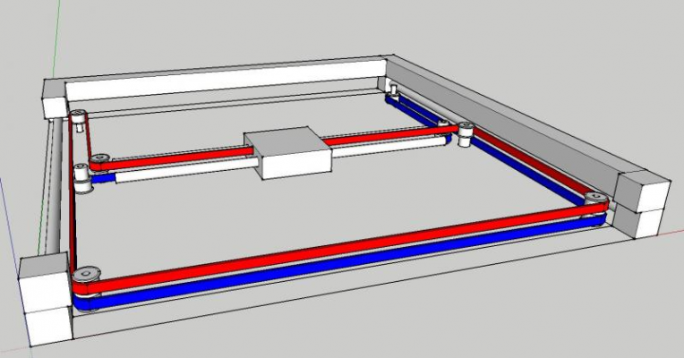
I've been looking at the stacked, coaxial pulley design and run into one problem with it. Using 20 tooth pulleys on the motors, when the X axis is farthest (why does that word seem so wrong?) from the motors, the belt is in grave danger of interfering with itself due to the small angle created by the small motor pulley. I may add one more fixed pulley near each motor, then move the motors outward a few mm to open that angle up and provide more clearance for the belts.
The interference I'm talking about is best seen by ignoring one belt or the other. In this instance, consider the blue belt (ignore red). Since the pulleys are stacked, the blue belt will bend around the same pulley the red belt occupies in the upper right corner. Imagine the X axis slid all the way to the top of the drawing. Look at what happens with the blue belt. It very nearly touches itself. We can't have our belts touching themselves!
Some people move the motors inward and use two pulleys to bend the belt. If you just move the motor outward (to the right in this case), you need one pulley near the motor to keep the belt parallel to the Y axis. Hmmmm.......
Ultra MegaMax Dominator 3D printer: [drmrehorst.blogspot.com]
|
Re: Rugged CoreXY June 06, 2016 08:34AM |
Registered: 9 years ago Posts: 1,873 |
Quote
which you CANNOT DO with non-stacked belts
I'm missing something. Stacked belts (let's call them vertically offset) does not to me seem to require axially stacked pulleys in the top left and right corners of the diagram in DDs post. Vertically offset belts seem good, axially stacked pulleys seem bad.
|
Re: Rugged CoreXY June 06, 2016 08:36AM |
Registered: 8 years ago Posts: 776 |
Quote
the_digital_dentist
I've been looking at the stacked, coaxial pulley design and run into one problem with it. Using 20 tooth pulleys on the motors, when the X axis is farthest (why does that word seem so wrong?) from the motors, the belt is in grave danger of interfering with itself due to the small angle created by the small motor pulley.
not at all. if you believe it to be a problem make the frame larger. download the Fusebox 1.4 STL file, walk through it with meshlab. you'll find that a stacked design has absolutely no such problem. mind you the Fusebox is 450mm wide when the printbed's only 200.
Quote
I may add one more fixed pulley near each motor, then move the motors outward a few mm to open that angle up and provide more clearance for the belts.
if you are going to experiments, please bear in mind: 90 degree turns on and off the x-ends and into the carriage is CRITICAL. under no circumstances misalign the belts. they MUST come off the x-end idlers at absolute 90 degrees. this is ABSOLUTELY critical.
|
Re: Rugged CoreXY June 06, 2016 08:46AM |
Registered: 7 years ago Posts: 168 |
I think I may be using the term "stackable pulleys" in a different way.
I'm talking about the pair of pulleys at the end of the Y axis (opposite the motors) being both run on the same post/shoulder bolt, which I saw an article on somewhere, as opposed to the pair of idler pulleys on a separate post each.
I'm using the common pic all over the net as a reference:
I do get it about the twisting force in the carriage, and while the linears I'm using would probably handle it it certainly wouldn't be ideal.
So the belts must cross like that at the front? Is there a solution that doesn't run the belts skewed like that?
And THAT'S why he's got the X axis plate down in the hole level with the main plate, losing all that X travel, but i'm getting the same effect by running my pulleys on raised pedestals
And looking at this pic (and assuming it's done correctly) he does have the belts connected to the central carriage at different heights. Mind you he also has pieces of bronze bush epoxied to things as linear bearings.
What's the solution there that's going to work better?
Some sort of offset belt clamp/bracket?
Edited 2 time(s). Last edit at 06/06/2016 08:53AM by hobbymods.
I'm talking about the pair of pulleys at the end of the Y axis (opposite the motors) being both run on the same post/shoulder bolt, which I saw an article on somewhere, as opposed to the pair of idler pulleys on a separate post each.
I'm using the common pic all over the net as a reference:

I do get it about the twisting force in the carriage, and while the linears I'm using would probably handle it it certainly wouldn't be ideal.
So the belts must cross like that at the front? Is there a solution that doesn't run the belts skewed like that?
And THAT'S why he's got the X axis plate down in the hole level with the main plate, losing all that X travel, but i'm getting the same effect by running my pulleys on raised pedestals
And looking at this pic (and assuming it's done correctly) he does have the belts connected to the central carriage at different heights. Mind you he also has pieces of bronze bush epoxied to things as linear bearings.
What's the solution there that's going to work better?
Some sort of offset belt clamp/bracket?
Edited 2 time(s). Last edit at 06/06/2016 08:53AM by hobbymods.
|
Re: Rugged CoreXY June 06, 2016 09:26AM |
Registered: 8 years ago Posts: 776 |
Quote
hobbymods
I do get it about the twisting force in the carriage, and while the linears I'm using would probably handle it it certainly wouldn't be ideal.
very very busy, partly answering dd's question as well:

unless the belts are offset in height (stacked one above the other - different use of word "stacked") you can NOT do the above trick which eliminates twisting force under acceleration (due to small changes in belt tension on left and right caused by acceleration force).
black and purple dots represent x-end carriage bearings, which are offset in height. mirror it on other side. sorry being very very brief.
Quote
So the belts must cross like that at the front?
yes. they have to twist so that they miss each other... *just* about, by running back-to-back at the critical mid-point as they twist. which is pretty f*****g lame if you ask me. i honestly don't get how it's even physically possible, unless somehow in some lame way one or more of those idlers is slightly lifted up above the others, which runs the risk of the belt trying to worm its way off the idler.
Quote
Is there a solution that doesn't run the belts skewed like that?
YES! take a look at the Fusebox!!!! said it for the third time!!! *dings hobbymod around the 'earole*

|
Re: Rugged CoreXY June 06, 2016 09:52AM |
Registered: 9 years ago Posts: 346 |
Quote
lkcl
Quote
hobbymods
I do get it about the twisting force in the carriage, and while the linears I'm using would probably handle it it certainly wouldn't be ideal.
very very busy, partly answering dd's question as well:
...
unless the belts are offset in height (stacked one above the other - different use of word "stacked") you can NOT do the above trick which eliminates twisting force under acceleration (due to small changes in belt tension on left and right caused by acceleration force).
black and purple dots represent x-end carriage bearings, which are offset in height. mirror it on other side. sorry being very very brief.
I do not agree that this twisting force will have any effect on printer performance. The angle turning at such a short distance is minimal. The friction from the twisting can easily be handled with proper dimensions. Also, the distance between the two attachment points can be minimized to within 2mm (I say min 2 mm between running belts), no rules says the belts has to be far apart. The design you say will give problems is extensively used in so many printers. Remember, we are only talking about the dynamic forces from the acceleration.
@ The Digital Dentist -
If I understand your question correctly, then the answer for you may be to have different sized pulleys on the same shaft? Will that not solve the issue?
@ Topic:
In general one pulley must always be dislocated from the 90 deg rectangle or an idler must be used, as per below sketches:

These are just some of many, many options. The belt paths are generally not that much of an issue I think. The difficult part in printer design is really the Z axis and stability of the frame because of the high speed mass running high up.
Just try to avoid attaching the belts at a plane much higher then the smooth rods and not too far apart and remember to keep 90 deg with the belts that has changing distances to pulleys
//Edit: Better image.
Edited 1 time(s). Last edit at 06/06/2016 09:55AM by LarsK.
|
Re: Rugged CoreXY June 06, 2016 10:04AM |
Registered: 7 years ago Posts: 168 |
[/quote]YES! take a look at the Fusebox!!!! said it for the third time!!! *dings hobbymod around the 'earole* [/quote]
I should point out that I'm 120kgs of mining contractor, which is a. why I'm dumb at this and b. why you'd only clip my earole once.
But all levity aside, I've looked at the fusebox (very nice) previously the first time you mentioned it and again now, and my belts are run the same way it looks to me.
Problem is that I've only shown some posts without belts on them, and I've confused the issue with my misuse of the term stacking. My fault that.
Firstly my belts are stacked, one is run above the other, so we're good there.
I've got it about the importance exact 90 degrees when the belt rounds the pulley and heads along the X axis, that's how I did it.
The only difference I see is that he's used a single idler post on each end of the X axis with the pulleys on top of each other, rather than the 2 separate idlers I and the pic above have used. Which actually looks like a good way to do it.
I thought you were saying the points where the belts fixed to the central carriage (that holds the extruder/hot end) had to be at the same height, which they are not both on the fusebox and the pic above, to avoid twisting.
I need to finish my mockup with some tape of ribbon in place so that the belt paths are clear.
So let's chill a bit and I'll put up a clearer pic in coming days.
[/quote]I should point out that I'm 120kgs of mining contractor, which is a. why I'm dumb at this and b. why you'd only clip my earole once.
But all levity aside, I've looked at the fusebox (very nice) previously the first time you mentioned it and again now, and my belts are run the same way it looks to me.
Problem is that I've only shown some posts without belts on them, and I've confused the issue with my misuse of the term stacking. My fault that.
Firstly my belts are stacked, one is run above the other, so we're good there.
I've got it about the importance exact 90 degrees when the belt rounds the pulley and heads along the X axis, that's how I did it.
The only difference I see is that he's used a single idler post on each end of the X axis with the pulleys on top of each other, rather than the 2 separate idlers I and the pic above have used. Which actually looks like a good way to do it.
I thought you were saying the points where the belts fixed to the central carriage (that holds the extruder/hot end) had to be at the same height, which they are not both on the fusebox and the pic above, to avoid twisting.
I need to finish my mockup with some tape of ribbon in place so that the belt paths are clear.
So let's chill a bit and I'll put up a clearer pic in coming days.
|
Re: Rugged CoreXY June 06, 2016 10:12AM |
Registered: 9 years ago Posts: 346 |
Quote
hobbymods
And THAT'S why he's got the X axis plate down in the hole level with the main plate, losing all that X travel, but i'm getting the same effect by running my pulleys on raised pedestals
And looking at this pic (and assuming it's done correctly) he does have the belts connected to the central carriage at different heights. Mind you he also has pieces of bronze bush epoxied to things as linear bearings.
What's the solution there that's going to work better?
Some sort of offset belt clamp/bracket?
Same plane belts can be implemented in many ways. But you are right that the belts have to change in Z height to pass each other. They do not have to twist* like IKCL says, they just have to be raised to different Z levels. This is done proper by angling the idlers.
* IT can be an advantage to also twist them to get the flat side on the idlers, but this is true for any belt path.
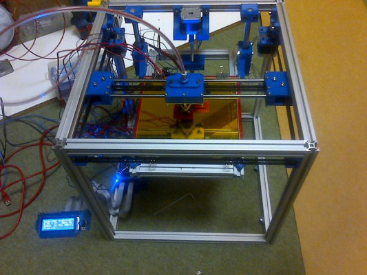
This is my printer that does this:


The pictures are from the build process, I later changed the green idler brackets as they were not strong enough, but the concept is the same.
|
Re: Rugged CoreXY June 06, 2016 10:26AM |
Registered: 8 years ago Posts: 776 |
Quote
LarsK
I do not agree that this twisting force will have any effect on printer performance.
agreed. it just isn't good for the carriage bearings.
Quote
Also, the distance between the two attachment points can be minimized to within 2mm (I say min 2 mm between running belts), no rules says the belts has to be far apart.
that didn't occur to me. that would work well
Quote
The design you say will give problems is extensively used in so many printers. Remember, we are only talking about the dynamic forces from the acceleration.
correct. which is of concern for me as i am putting in values of 7500mm/s^2 for the sandwich200v2 acceleration config. and will be increasing that in tests later when i've sorted out the carriage.
|
Re: Rugged CoreXY June 06, 2016 10:31AM |
Registered: 8 years ago Posts: 776 |
Quote
hobbymods
Quote
YES! take a look at the Fusebox!!!! said it for the third time!!! *dings hobbymod around the 'earole*
I should point out that I'm 120kgs of mining contractor, which is a. why I'm dumb at this and b. why you'd only clip my earole once.
teehee
Quote
But all levity aside, I've looked at the fusebox (very nice) previously the first time you mentioned it and again now, and my belts are run the same way it looks to me.
Problem is that I've only shown some posts without belts on them, and I've confused the issue with my misuse of the term stacking. My fault that.
Firstly my belts are stacked, one is run above the other, so we're good there.
I've got it about the importance exact 90 degrees when the belt rounds the pulley and heads along the X axis, that's how I did it.
The only difference I see is that he's used a single idler post on each end of the X axis with the pulleys on top of each other, rather than the 2 separate idlers I and the pic above have used. Which actually looks like a good way to do it.
yes. i made that change because i wanted the belts to come in dead-centre. two extra bolts. less wear on linear rails. worth it.
Quote
I thought you were saying the points where the belts fixed to the central carriage (that holds the extruder/hot end) had to be at the same height, which they are not both on the fusebox and the pic above, to avoid twisting.
I need to finish my mockup with some tape of ribbon in place so that the belt paths are clear.
So let's chill a bit and I'll put up a clearer pic in coming days.
ack.
yeah it would be great to have the two belts come in at the same height as well as the same y-coordinate, but that's literally impossible to achieve (belts occupying same space)
however LarsK mentions a great idea, put them in the same plane and bring them in only 2mm apart on the x-ends. that would do it.
only thing is i *really* don't like the idea of lifting some of the idlers to make the belts able to cross over at the back, that's just so disgusting, as you need to put the idler bolts at a very tiny angle, but you still end up with one edge being a different length from the other, so the belt will ride up and down and could actually try to work its way off the idler. yuck.
|
Re: Rugged CoreXY June 06, 2016 10:40AM |
Registered: 7 years ago Posts: 168 |
|
Re: Rugged CoreXY June 06, 2016 11:19AM |
Registered: 9 years ago Posts: 1,873 |
Quote
LarsK
Also, the distance between the two attachment points can be minimized to within 2mm (I say min 2 mm between running belts), no rules says the belts has to be far apart.
The attachment points on the X carriage? As far as I can see, there's no relative motion between the belts once they enter the X axis. You can clamp the belts together on the X carriage if you want. It would be cute to have the belts tooth to tooth so they zip and unzip as the roll on and off the X axis, but that doesn't seem possible with the default belt layout. But, I have no experience of building a coreXY, so I maybe not seeing something right.
|
Re: Rugged CoreXY June 06, 2016 11:55AM |
Registered: 8 years ago Posts: 622 |
Quote
the_digital_dentist
Quote
deckingman
...Anyway, the reason for using 1mm pitch is that (as I mentioned), I'm planning on using the lead screws for bed levelling. It may not work but my thinking is that I have 3 point lifting so why not use it for bed levelling as well?
If the bed is going to be heated, you're still going to stand it off an undercarriage that's connected to the lead screws. Those fine pitch stand-off screws can be used to set the bed level when you first set up the machine.
Actually I'm not planning on any stand-off arrangement. The plan is for the bed to be a sandwich of rigid insulator, heater, heater spreader plate, and then removable glass print surface. The rigid insulator is fixed to the linear guides using a ball joint arrangement so that the bed will be constrained in the XY plain so there is no wobble, but can be allowed to tilt without imparting any twisting force. The lead screws can "float" in the XY plain as they are only supporting the bed and providing vertical lift. So the lead screws could be used for initial levelling. Just slacken the pulley retainer, turn the screw to level the bed, then tighten the pulley retainer. The bed will "swivel" up and down on the ball joints. Of course, this is only a plan. The design will allow me easily change it to a stand off arrangement if it doesn't work. At least having 1mm pitch lead screws at the outset gives me the option. The more I think about these multi start, course pitch lead screws for Z, the more I think they are a bad idea. 1mm pitch means that I have 20 full steps per 0.1mm whereas the more common 2mm/4 start lead screw has an 8mm pitch which means 2 and half full steps per 0.1mm. So I'd be relying on micro stepping to give the half step and I can't help thinking that relying on micro stepping for positional accuracy is a bad idea. Maybe I'm wrong? I've also read that typical stepper motors have a positional accuracy of +/-5% per step although this is non accumulative but even so, it could be significant when using a very small number of steps. And of course, micro stepping does not improve this accuracy merely the resolution. But what do I know? I'm just an old guy that cuts and screws bits of wood together for living. I'll build it and see if it works.
|
Re: Rugged CoreXY June 06, 2016 12:23PM |
Registered: 9 years ago Posts: 346 |
Quote
JamesK
Quote
LarsK
Also, the distance between the two attachment points can be minimized to within 2mm (I say min 2 mm between running belts), no rules says the belts has to be far apart.
The attachment points on the X carriage? As far as I can see, there's no relative motion between the belts once they enter the X axis. You can clamp the belts together on the X carriage if you want. It would be cute to have the belts tooth to tooth so they zip and unzip as the roll on and off the X axis, but that doesn't seem possible with the default belt layout. But, I have no experience of building a coreXY, so I maybe not seeing something right.
You are right. That would look really nice. I must have spent so much time thinking about the other belts that I never realized that these particular ones can run together. That said, it is not relevant in my current single-plane build (as I am running the belts in the 2020 profile). Another advantage of single plane is that you can use a single belt, just clamp it on the middle at the carriage.
All that said, I actually prefer two plane belts now. Ikcl is right that the idler angle has to be perfect for the belts to not migrate up and down. Then you have to install shoulders on the idlers to keep the belts and they wear... I have run a couple of hundred hours on mine and I need to change the printed plastic shoulders. No big issue but not a problem on two planes.
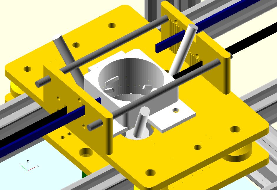
One thing nobody has talked about - Does the belt go above the rods or in between (behind) the rods.
This is my new design on one of my printers:

SO here you see the belt goes behind the smooth rod. It could also go above and under but that would take up more space and induce a bigger vertical twist
|
Re: Rugged CoreXY June 06, 2016 01:49PM |
Registered: 10 years ago Posts: 344 |
|
Re: Rugged CoreXY June 06, 2016 01:54PM |
Registered: 9 years ago Posts: 1,873 |
Hmm, it's an interesting question re the rods. I guess it hinges on whether you feel the construction of the Y carriages is sufficiently stiff. It would be easier to make a robust Y carriage with the rods overlapping than with the X and Y rods co-planar. Leaving a gap for the belt to get between the X and Y rods would make life more difficult still. An interesting challenge.
|
Re: Rugged CoreXY June 06, 2016 03:13PM |
Registered: 10 years ago Posts: 344 |
|
Re: Rugged CoreXY June 06, 2016 03:47PM |
Registered: 8 years ago Posts: 622 |
Here are some pics of my pathetic attempt. The monstrous contraption in white is a Diamond hot end assembly complete with it's heat sinks and bits of Bowden tube sticking out. The belt layout is basically as per the reference mechanism but with one belt higher than the other which means they can cross without interference. At the end of the X axes, the bearings are stacked on top of each other which brings them closer together and closer to the centre line. I couldn't figure out a way for the idlers in the corners to be stacked on top of each other and still keep the belts parallel to the axes so they are offset as per the reference mechanism but also at different heights (to each other). I've designed the X carriage with printed ridges the same size and spacing as gt2 belt. I'm planning to pass tghe belts through the slots then bend them over these ridges and clamp them in place. There are a couple of tie rods (shown as horizontal grey cylinders) which'll be threaded rod with washers and nyloc nuts on the ends to equalise the belt tension and take the strain away from the upright parts on the carriage. Belt tensioning will be accomplished by a thumb screw which will jack the motor away from the frame (the frame mount has a slotted hole at the top but the side mounting screws will be going into tee nuts and can slide along the rails). Anyway, it all looks like it's square and parallel and all the corners are right angles where it matters. No doubt someone will step in and quickly blow this out of the water though.....
|
Re: Rugged CoreXY June 06, 2016 05:59PM |
Registered: 7 years ago Posts: 168 |
Quote
deckingman
Here are some pics of my pathetic attempt. The monstrous contraption in white is a Diamond hot end assembly complete with it's heat sinks and bits of Bowden tube sticking out. The belt layout is basically as per the reference mechanism but with one belt higher than the other which means they can cross without interference. At the end of the X axes, the bearings are stacked on top of each other which brings them closer together and closer to the centre line. I couldn't figure out a way for the idlers in the corners to be stacked on top of each other and still keep the belts parallel to the axes so they are offset as per the reference mechanism but also at different heights (to each other). I've designed the X carriage with printed ridges the same size and spacing as gt2 belt. I'm planning to pass tghe belts through the slots then bend them over these ridges and clamp them in place. There are a couple of tie rods (shown as horizontal grey cylinders) which'll be threaded rod with washers and nyloc nuts on the ends to equalise the belt tension and take the strain away from the upright parts on the carriage. Belt tensioning will be accomplished by a thumb screw which will jack the motor away from the frame (the frame mount has a slotted hole at the top but the side mounting screws will be going into tee nuts and can slide along the rails). Anyway, it all looks like it's square and parallel and all the corners are right angles where it matters. No doubt someone will step in and quickly blow this out of the water though.....
Not pathetic at all, don't say that.
I don't have the cad ability at all to do that, my examples are paddle pop sticks and plastic blocks lol.
I must say the thing I see in common with the Fusebox and the SOM is the print quality!!
That red bracket thing printed by the Fusebox is one of the best prints I've seen, and if it's quicker as well I'm inspired to make it happen.
I can see a second scrap of perspex I've got there being in mortal danger of being drawn on and cut up.
|
Re: Rugged CoreXY June 06, 2016 06:36PM |
Registered: 9 years ago Posts: 1,873 |
Quote
I can see a second scrap of perspex I've got there being in mortal danger of being drawn on and cut up.
I really like the way you prototype your ideas. I'm trying to get more familiar with CAD, but I always quickly run up to the point where I want to hold it and see how it feels for real.
There's some great creative energy running through this thread, and around coreXY in general. We could really do with an 'established' reprap coreXY design (or is there one that I've missed?), but it's fun watching everyone mashing ideas around right now.
|
Re: Rugged CoreXY June 06, 2016 07:21PM |
Registered: 7 years ago Posts: 168 |
Quote
JamesK
Quote
I can see a second scrap of perspex I've got there being in mortal danger of being drawn on and cut up.
I really like the way you prototype your ideas. I'm trying to get more familiar with CAD, but I always quickly run up to the point where I want to hold it and see how it feels for real.
There's some great creative energy running through this thread, and around coreXY in general. We could really do with an 'established' reprap coreXY design (or is there one that I've missed?), but it's fun watching everyone mashing ideas around right now.
Please bear in mind that I've only used closed PP3DP and Zortrax software in my entire time in the hobby, so apart from sending emails and surfing websites I'm good for bugger all on a computer.
That's where I'll struggle, but I hope to fall on the mercy of the people here.
BUT...I do have a pretty big background in technical fabrication, especially in items needed for use in aggressive environments, and hope to bring something of value here in that.
Yep....lovin' the vibe too, and yes one in the hand is worth 3 in the bush.
Edited 1 time(s). Last edit at 06/06/2016 07:22PM by hobbymods.
|
Re: Rugged CoreXY June 06, 2016 08:02PM |
Registered: 13 years ago Posts: 268 |
I've used many different CAD packages over the years, several of them professionally. To get really proficient in CAD to the point where you can design real usable parts that can be produced and assembled takes a while, and the only way to get better is practice. Most of them have pretty steep learning curves. There's some light at the end of the tunnel, I machined the parts for my delta once, and things fit and worked well the first time. I bought bearings, pulleys spacers, linear rails, motors, and even aluminum for the frame once and got what I needed. Only way to do that is by building it in CAD first, and checking everything important.Quote
JamesK
Quote
I can see a second scrap of perspex I've got there being in mortal danger of being drawn on and cut up.
I really like the way you prototype your ideas. I'm trying to get more familiar with CAD, but I always quickly run up to the point where I want to hold it and see how it feels for real.
There's some great creative energy running through this thread, and around coreXY in general. We could really do with an 'established' reprap coreXY design (or is there one that I've missed?), but it's fun watching everyone mashing ideas around right now.
|
Re: Rugged CoreXY June 06, 2016 08:50PM |
Registered: 11 years ago Posts: 1,049 |
I got a headache reading all the stuff on stacked belt bearings
a drawing of two level system
Let you guys rip it apart ????

a drawing of two level system
Let you guys rip it apart ????

|
Re: Rugged CoreXY June 06, 2016 09:12PM |
Registered: 9 years ago Posts: 346 |
Quote
cozmicray
I got a headache reading all the stuff on stacked belt bearings
a drawing of two level system
Let you guys rip it apart ????
[attachment 79368 two_level_belt.jpg]
Nice drawings. Just, it is not that simple. The design you just sketched offset one of the idlers on the y carriages into the print area. Since this happen on both sides you loose 2x bearing size as potential print area. Using 16 mm idlers and you just lost 32 mm print area compared to if you had offset the motors outwards instead…
|
Re: Rugged CoreXY June 06, 2016 11:54PM |
Registered: 11 years ago Posts: 1,049 |
Huh
I don't care what the outer dimensions of my printer are
do the pulleys have to be in print area?
If my Y axis linear guide is 500mm
and trolley is 30mm
and the beams spacing the Y rails are 800mm
My max print area is determined by guide trolley travel
I should have 150mm on each side to hold all the pulleys, belts,
motors etc.
Same on X axis?
Or is my headache causing a BSOD?
(Blue Screen Of Death)
Another Drawing from my pea on my neck (its too late)

Quote
LarsK
Quote
cozmicray
I got a headache reading all the stuff on stacked belt bearings
a drawing of two level system
Let you guys rip it apart ????
[attachment 79368 two_level_belt.jpg]
Nice drawings. Just, it is not that simple. The design you just sketched offset one of the idlers on the y carriages into the print area. Since this happen on both sides you loose 2x bearing size as potential print area. Using 16 mm idlers and you just lost 32 mm print area compared to if you had offset the motors outwards instead…
|
Re: Rugged CoreXY June 07, 2016 12:52AM |
Registered: 10 years ago Posts: 344 |
|
Re: Rugged CoreXY June 07, 2016 05:56AM |
Registered: 8 years ago Posts: 776 |
Quote
LarsK
One thing nobody has talked about - Does the belt go above the rods or in between (behind) the rods.
This is my new design on one of my printers:
SO here you see the belt goes behind the smooth rod. It could also go above and under but that would take up more space and induce a bigger vertical twist
very nice arrangement. like the belts being the inner side of the rods. offset above and below... all belts come in on centre... yes i do the thing where the belts go behind the moving x-rods as well, that made sense to me, keep them as close to a centre-line (vertically) as possible.
what you've done here LarsK is i think about the closest it's possible to get to being balanced under acceleration and reduce acceleration-induced bearing side-wall loading.
putting the belts inboard from the y-rods also means the y-rod bearings are not torqued (side-loaded) as well, which is great.
thought about what you, jamesk and hobbymods i think mentioned yesterday, with stacked (height-offset) belts the difference in height could produce torquing of the carriage about the.... *thinks*... Y-axis under heavy acceleration. so keeping them as close together but also an equal distance above and below the line of the x rods would be good, and i think that's what you did in that new design, LarsK.
only one other consideration - keeping the centre of gravity of the carriage as close to the rods as possible *and* keeping the hotend as far up as is possible... two rather diametrically-opposed things unfortunately oh well
|
Re: Rugged CoreXY June 07, 2016 06:33AM |
Registered: 7 years ago Posts: 168 |
Quote
lkcl
Quote
LarsK
One thing nobody has talked about - Does the belt go above the rods or in between (behind) the rods.
This is my new design on one of my printers:
SO here you see the belt goes behind the smooth rod. It could also go above and under but that would take up more space and induce a bigger vertical twist
very nice arrangement. like the belts being the inner side of the rods. offset above and below... all belts come in on centre... yes i do the thing where the belts go behind the moving x-rods as well, that made sense to me, keep them as close to a centre-line (vertically) as possible.
what you've done here LarsK is i think about the closest it's possible to get to being balanced under acceleration and reduce acceleration-induced bearing side-wall loading.
putting the belts inboard from the y-rods also means the y-rod bearings are not torqued (side-loaded) as well, which is great.
thought about what you, jamesk and hobbymods i think mentioned yesterday, with stacked (height-offset) belts the difference in height could produce torquing of the carriage about the.... *thinks*... Y-axis under heavy acceleration. so keeping them as close together but also an equal distance above and below the line of the x rods would be good, and i think that's what you did in that new design, LarsK.
only one other consideration - keeping the centre of gravity of the carriage as close to the rods as possible *and* keeping the hotend as far up as is possible... two rather diametrically-opposed things unfortunately oh well
Yep I'm feeling this one too.
I'm really leaning towards using 2x 10mm ground rods across the center (X) axis, there's just so many reasons.
Of course there's the fact that it'll cost 10% of what my precision rail setup would, but then there's probably half the weight, 2 less major machining/tool making steps, the ability to slide the rods out and change carriages (CNC/laser engraver attachment) and the fact that it'll probably work just as well using proper ground/hardened rod and 4x brand name LM10U bearings.
I think I'll go this way and see if it all works out.
Edited 1 time(s). Last edit at 06/07/2016 06:34AM by hobbymods.
|
Re: Rugged CoreXY June 07, 2016 07:02AM |
Registered: 8 years ago Posts: 776 |
Quote
hobbymods
Yep I'm feeling this one too.
I'm really leaning towards using 2x 10mm ground rods across the center (X) axis, there's just so many reasons.
Of course there's the fact that it'll cost 10% of what my precision rail setup would, but then there's probably half the weight, 2 less major machining/tool making steps, the ability to slide the rods out and change carriages (CNC/laser engraver attachment) and the fact that it'll probably work just as well using proper ground/hardened rod and 4x brand name LM10U bearings.
I think I'll go this way and see if it all works out.
talked this one through with realthor just over a week ago, we figured that if you use linear bearings, as long as you keep the linear bearings as far apart as you dare, any "play" in them will not result in significant rotation of the carriage. if there _is_ any play, gravity shouuuld keep it down, but even if there is, the further apart the bearings are the less effect any up/down will have... as long as the hotend is as close to the dead-centre-point of the carriage bearings as you dare. having the bearings so close to the printbed that they knock bits of plastic off is clearly bad...


Sorry, only registered users may post in this forum.