Rugged CoreXY
Posted by hobbymods
|
Re: Rugged CoreXY July 18, 2016 01:33AM |
Registered: 7 years ago Posts: 168 |
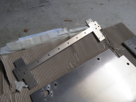
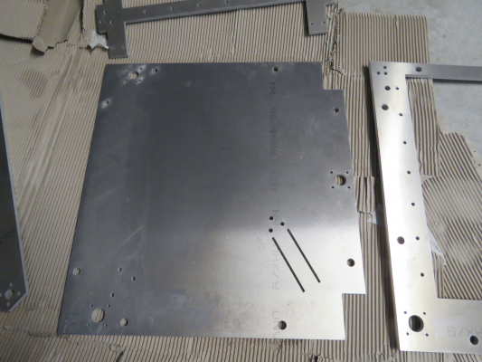
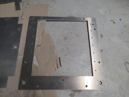
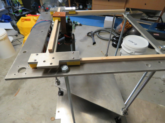
Sent my first bits off to the waterjet cutter today...gantry, X axis, floor and bed support plates.
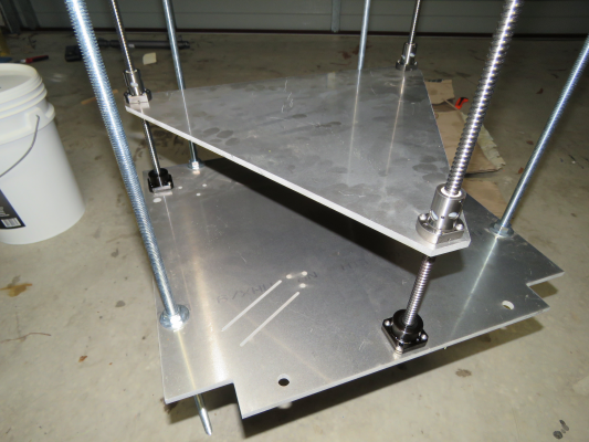
I've put holes for 12mm threaded rod on each side so I can support it all without making the walls (if that makes sense), and see how my triple screw Z axis lines up.
Old mate was delighted with my DXF files and said he'd turn it around quick and cheap for me. Reckons he normally gets a scan of a bit of paper with hand drawn sketches on it from "nut case inventors like me", which he has to drop tools and design for them which he hates, as they don't want to pay for it. So a tip there....do your own DXF files and keep them on side and the costs down when dealing with laser/waterjet cutting companies.
Really on a tight budget at the moment, and these pieces will probably only be mockups, but there's only so much I can do with hand cut acrylic now and it's time for live fire prototyping.
|
Re: Rugged CoreXY August 17, 2016 01:58AM |
Registered: 7 years ago Posts: 168 |
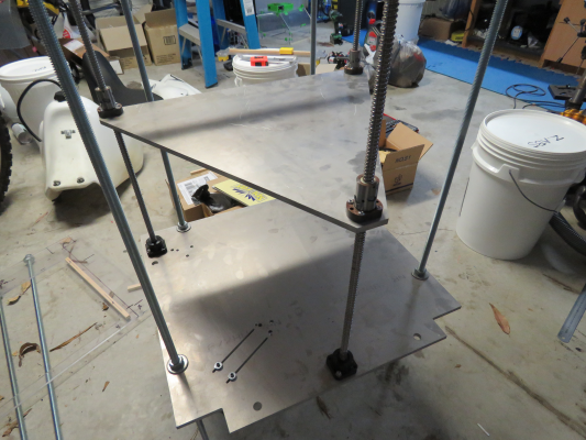
Got my bits back from the water jet guys.
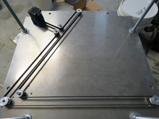
Bit tight with the budget at the moment, but I've got everything I need to set up all the moving bits using threaded rod between the top and bottom as a temporary frame, and I'll print all the pulley mounts etc for now.
Bit tight with the budget at the moment, but I've got everything I need to set up all the moving bits using threaded rod between the top and bottom as a temporary frame, and I'll print all the pulley mounts etc for now.
|
Re: Rugged CoreXY August 30, 2016 02:01AM |
Registered: 7 years ago Posts: 168 |
Bit further along, doing what I can without spending any more money.
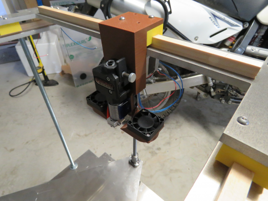
A few mistakes in my grand design...the whole X axis "dog bone" gantry plate will be reviewed.
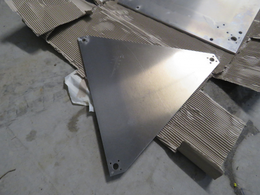
The triangular build plate support is only a temporary mockup to allow me to test my triple Z screw plan, and obviously the threaded rods are in lieu of walls right now.
I'll save up now for all my XY linear guides, and start making some printed parts (to be replaced down the line with CNC ally) to support all my pulleys etc.
I'm likely to be like the writer and his novel on this, could take years, but I feel good about how it's going so far.
|
Re: Rugged CoreXY June 03, 2017 07:37PM |
Registered: 7 years ago Posts: 168 |
I ran out of money on this, and as the next step involves real money (linears and more water jet cutting) I've put it on the back burner for now. Just can't afford anything at the moment.
I used the electronics in this:
[www.duet3d.com]
Which has worked out very well, and might get me some paying work again.
I've got 3 more busted Zortrax's there (keep blowing boards), so I'll convert another as above and might look at using some of the pulleys and belts I bought to convert one to corexy.
Like writing a book, this one might take a couple of years.
|
Re: Rugged CoreXY June 03, 2017 11:44PM |
Registered: 8 years ago Posts: 776 |
Quote
hobbymods
Old mate was delighted with my DXF files and said he'd turn it around quick and cheap for me. Reckons he normally gets a scan of a bit of paper with hand drawn sketches on it from "nut case inventors like me", which he has to drop tools and design for them which he hates, as they don't want to pay for it. So a tip there....do your own DXF files and keep them on side and the costs down when dealing with laser/waterjet cutting companies.
i've used [www.themetalstore.co.uk] in the past and they're really good - but yes, you have to send them a DXF file, not sketches...

|
Re: Rugged CoreXY June 04, 2017 07:02AM |
Registered: 11 years ago Posts: 5,780 |
I don't think the threaded rods that are separating the top and bottom plates are going to be rigid enough for printing at even reasonable speeds. You're going to be moving quite a bit of weight around at print speed at the top of the machine and it's going to make the frame shake and wobble. The top and bottom plates will flex with the long lever arms of the threaded rods, and threaded rods themselves aren't terribly rigid- the cross sectional area is pretty small. Adding side and back panels should stiff things up considerably.
Ultra MegaMax Dominator 3D printer: [drmrehorst.blogspot.com]
Ultra MegaMax Dominator 3D printer: [drmrehorst.blogspot.com]
|
Re: Rugged CoreXY June 04, 2017 07:39AM |
Registered: 8 years ago Posts: 776 |
good call dd! hobbymods i hope you weren't planning to leave this printer without a frame, but it's always good to check! it'll also need a base-plate as well, otherwise it'll not be properly rigid. take a cardboard box, open the top, what happens? the whole thing flops about. close it back up, tape up the top and voila: one rigid box. you can also cut open holes in the centre of every panel and still get away with it. documented here, see "cube example". [reprap.org]
i'm staggered at how complex it really is to make something as innocuously-simple as a rigid cube: eight corners requiring a minimum of 3 fasteners per corner, preferably 6, then along the edges you also need attachments (at the least in the middle), that's 12 of those (there are 12 edges on a cube) with a minimum of 2 fastenings... it's really quite, quite mad.
i'm staggered at how complex it really is to make something as innocuously-simple as a rigid cube: eight corners requiring a minimum of 3 fasteners per corner, preferably 6, then along the edges you also need attachments (at the least in the middle), that's 12 of those (there are 12 edges on a cube) with a minimum of 2 fastenings... it's really quite, quite mad.
|
Re: Rugged CoreXY June 05, 2017 07:11AM |
Registered: 7 years ago Posts: 168 |
Quote
the_digital_dentist
I don't think the threaded rods that are separating the top and bottom plates are going to be rigid enough for printing at even reasonable speeds. You're going to be moving quite a bit of weight around at print speed at the top of the machine and it's going to make the frame shake and wobble. The top and bottom plates will flex with the long lever arms of the threaded rods, and threaded rods themselves aren't terribly rigid- the cross sectional area is pretty small. Adding side and back panels should stiff things up considerably.
Actually....seriously, no.
I wasn't planning to use the threaded rods as a frame, there's a whole water just cut folded 5mm ally fascia, and a 10mm rear plate with the linear bearing mount surfaces machined into it, all fully welded. They are just there to position the prototype.
Of course you couldn't be expected to know that.
Like I said I've run completely out of coin for this project, which is a shame.
The design is for a completely enclosed, rigid ally enclosure with flats machined into it to mount the linear bearings, with a molded clear perspex dome over the top.
At this stage it's on hold, but given what I've spent already, not forgotten.
I'll be back when I've got 2-3k more to spend on it.
A thought that crossed my mind was to use an ABS/carbon fiber blend filament to print all the pulley and extruder mounts for the prototype. These would give good strength and heat resistance at a fraction of the cost of CNC machined ally parts.
Edited 1 time(s). Last edit at 06/05/2017 08:19AM by hobbymods.
|
Re: Rugged CoreXY June 14, 2017 01:10AM |
Registered: 7 years ago Posts: 168 |
OK,
I was so horrified that you guys thought I'd use threaded rod as a frame, and that there was even a lecture about the weakness of a cardboard box with no lid on it (WTF?!), that I've dusted this thing off for another look.
One of the things that ground me to a halt (other than work/kids/money/etc) was that I just couldn't find the pulleys I wanted to use, without getting into custom items. I really wanted my 9mm GT2 belts to be on toothed idlers when turning on the toothed side, and I don't like the little 20T chinese ones because of their crappy bearings and small 5mm shafts.
I'd forgotten that I'd ordered the 608 flanged bearings that DD recommended, and had them sitting there. Despite having no teeth, they are a nice solid solution and will do just fine on 8mm shoulder screws, so they will be what I use.
Also making me happy, my 3 lead screw Z platform works beautifully. Took a little setting up, and now the pulleys are different I had to drill some new holes, but it winds from top to bottom without any variation in level whatsoever. There will be 2 linear guides on the rear wall as well, but it looks good so far. I didn't run the belt as a triangle, as I want room for my power supply, motherboard, SSR, etc down in the bottom there.
Another change will be that I will use the Bondtech BMG extruder, which is much lighter and smaller, and specifically for 1.75mm direct drive.
There's a motor bike sitting there that is rarely used and the cause of several injuries....it's up for sale to fund this venture further.
|
Re: Rugged CoreXY June 14, 2017 01:20AM |
Registered: 7 years ago Posts: 168 |
Some questions regarding pulleys:
Is there a preference between 20T and 16T timing pulleys?
I've got 20T on the Z motor, and 40T on the Z screws, and I was planning to use 20T on the XY motors.
Is there any reason to prefer 16T?
Regarding steppers:
I was considering these for XY, simply because they're a commonly used motor, have a plug and are available in Oz. With my now much lighter carriage I figured that they'd be fine set at 1.4A.
[au.omc-stepperonline.com]
Then I was thinking about this for the Z axis, which will be big and heavy, and have a fairly tight belt system. Mind you, if 3 of the above motor will work that's fine too.
[au.omc-stepperonline.com]
Would love to here some suggestions there, especially if they're sitting there in the same steppers online Aus site.
|
Re: Rugged CoreXY June 14, 2017 04:55AM |
Registered: 8 years ago Posts: 776 |
Quote
hobbymods
OK,
I was so horrified that you guys thought I'd use threaded rod as a frame, and that there was even a lecture about the weakness of a cardboard box with no lid on it (WTF?!),
that's not a very nice thing to say, hobbymods! you're seriously underestimating the value of what i said. flexible materials have the significant advantage of demonstrating (amplifying) design weaknesses. and also have the advantage of taking minutes to assemble a demo / proof-of-concept, from scrap materials that you'll have lying around the house.
whilst everyone else on this forum takes sometimes *months* to verify a design concept, by virtue of them forcing themselves to either implement it fully with CAD software or spend hundreds to thousands of dollars buying materials and actually assembling it, only to find that there's a significant design flaw and they are forced to start again, using cardboard, paper, straws and (strong) tape i am often done in a few hours, giving me full confidence that i can proceed to a CAD design and an actual build, with far less risk and in far less time.
so be kind ok!
also, if you have (had) CAD screenshots dd would have been unlikely to assume that you intended to use the leadscrews (only) for support. this has been a long thread (lots of questions, lots of answers, which we all love doing) if you already did publish some, many many apologies, but that's the nature of forums: nobody remembers (or reads) prior messages on 200+ long threads. can i recommend you create a wiki page on reprap.org so that "static" information is there and can be referred to? you could then put that link into your .sig so that it's always there. things like the 608 bearings you ordered, you could list them on the wiki page, so that even you don't forget.
what do you think?
Quote
Also making me happy, my 3 lead screw Z platform works beautifully. Took a little setting up, and now the pulleys are different I had to drill some new holes, but it winds from top to bottom without any variation in level whatsoever. There will be 2 linear guides on the rear wall as well, but it looks good so far.
nice. i'm a big fan of that arrangement. 3 leads and 2 rails is the minimum and it's *really* effective. doesn't need particularly heavy-duty leads or heavy-duty rails either.
Quote
Another change will be that I will use the Bondtech BMG extruder, which is much lighter and smaller, and specifically for 1.75mm direct drive.
ooo those look reaaally nice! zowee, $80 though. but only 22g so it's seriously worth considering. i like that they're direct-drive and have an internal 3:1 gear ratio, you could consider using lower-spec NEMA17s (lighter weight).
i remember seeing dc42's advice about NEMA17s: he said really, don't bother getting anything other than 0.9deg steppers these days, or running them at anything less than 24v. thought that was worth relaying.
also have you looked at mutley3d's direct-drive flex3drive? drop-in adapter for a NEMA17, it moves the "power" out to a static location, taking away the weight of the NEMA17 but providing far better accuracy, control and a massive reduction in torque, all at the same time. [flex3drive.com]
|
Re: Rugged CoreXY June 14, 2017 06:31AM |
Registered: 7 years ago Posts: 168 |
Quote
lkcl
Quote
hobbymods
OK,
I was so horrified that you guys thought I'd use threaded rod as a frame, and that there was even a lecture about the weakness of a cardboard box with no lid on it (WTF?!),
that's not a very nice thing to say, hobbymods! you're seriously underestimating the value of what i said. flexible materials have the significant advantage of demonstrating (amplifying) design weaknesses. and also have the advantage of taking minutes to assemble a demo / proof-of-concept, from scrap materials that you'll have lying around the house.
whilst everyone else on this forum takes sometimes *months* to verify a design concept, by virtue of them forcing themselves to either implement it fully with CAD software or spend hundreds to thousands of dollars buying materials and actually assembling it, only to find that there's a significant design flaw and they are forced to start again, using cardboard, paper, straws and (strong) tape i am often done in a few hours, giving me full confidence that i can proceed to a CAD design and an actual build, with far less risk and in far less time.
so be kind ok!
also, if you have (had) CAD screenshots dd would have been unlikely to assume that you intended to use the leadscrews (only) for support. this has been a long thread (lots of questions, lots of answers, which we all love doing) if you already did publish some, many many apologies, but that's the nature of forums: nobody remembers (or reads) prior messages on 200+ long threads. can i recommend you create a wiki page on reprap.org so that "static" information is there and can be referred to? you could then put that link into your .sig so that it's always there. things like the 608 bearings you ordered, you could list them on the wiki page, so that even you don't forget.
what do you think?
Quote
Also making me happy, my 3 lead screw Z platform works beautifully. Took a little setting up, and now the pulleys are different I had to drill some new holes, but it winds from top to bottom without any variation in level whatsoever. There will be 2 linear guides on the rear wall as well, but it looks good so far.
nice. i'm a big fan of that arrangement. 3 leads and 2 rails is the minimum and it's *really* effective. doesn't need particularly heavy-duty leads or heavy-duty rails either.
Quote
Another change will be that I will use the Bondtech BMG extruder, which is much lighter and smaller, and specifically for 1.75mm direct drive.
ooo those look reaaally nice! zowee, $80 though. but only 22g so it's seriously worth considering. i like that they're direct-drive and have an internal 3:1 gear ratio, you could consider using lower-spec NEMA17s (lighter weight).
i remember seeing dc42's advice about NEMA17s: he said really, don't bother getting anything other than 0.9deg steppers these days, or running them at anything less than 24v. thought that was worth relaying.
also have you looked at mutley3d's direct-drive flex3drive? drop-in adapter for a NEMA17, it moves the "power" out to a static location, taking away the weight of the NEMA17 but providing far better accuracy, control and a massive reduction in torque, all at the same time. [flex3drive.com]
Keep your shirt on, I knew you'd bite for that one. I wish you were a trophy fish.
Basically I was giving you credit for motivating me back on the job, whilst chafing your arse a bit just for the hell of it. '
Yes, I think the new BMG is the go.
No I hadn't heard that 0.9 degree steppers were the way forward (are they for corey/cartesian? I thought they were for delta's moreso).
Yes I've looked at mutleys flex3drive, but don't want to use it. I use his Printbite surface by the way and love it.
My whole project so far is only proof of concept.
I can't do fancy cad drawings...I actually build things and try them.
And cheers for yours and everyone elses points and tips.
|
Re: Rugged CoreXY June 14, 2017 07:25AM |
Registered: 8 years ago Posts: 776 |
Quote
hobbymods
Keep your shirt on, I knew you'd bite for that one. I wish you were a trophy fish.
haha aaand i fell for it

Quote
Basically I was giving you credit for motivating me back on the job, whilst chafing your arse a bit just for the hell of it. '

Quote
Yes, I think the new BMG is the go.
No I hadn't heard that 0.9 degree steppers were the way forward (are they for corey/cartesian? I thought they were for delta's moreso).
one of the problems with the 200steps/rev motors is, you have to use 1/2 the level of micro-stepping to achieve the same accuracy as for a 400steps/rev motor. the problem with _that_ is that the static resistance (losses) inherent in microstepping result in a disproportionate (appx square-law) reduction in available torque. additionally, 24v vs 12v gives a four-fold increase in power (W = V^2/R).
the combination of these two factors gives you a much greater efficiency and/or greater torque for the same wattage. in scenarios where you're using 1/16 microstepping and 1.4A @ 12V with 1.8 degree steppers you could say... use... 1/8th microstepping and say... 0.8A or something like that (you'd have to do the calculations yourself to get accurate numbers).
Quote
Yes I've looked at mutleys flex3drive, but don't want to use it.
well that extruder plus a smaller weight stepper (because of the built-in 3:1 drive) would get you pretty close to some of the characteristics of a flex3drive. look forward to hearing how it works out.
Quote
I use his Printbite surface by the way and love it.
yehyeh, i've been thinking how that stuff actually works, i think it has a high thermal expansion coefficient which pops the object off the printbed as it cools down. he's got a new version he's working on which uses carbon fibre.
Quote
My whole project so far is only proof of concept.
I can't do fancy cad drawings...I actually build things and try them.
well you've done pretty damn good so far, i feel that's because you're happy to thoroughly research before taking action. that's a good thing: i tend to rush ahead and get things wrong... or not leave enough time for people to offer advice which i should really have listened to... whoops

Quote
And cheers for yours and everyone elses points and tips.
*thumbs-up* -
Edited 1 time(s). Last edit at 06/14/2017 07:26AM by lkcl.
Sorry, only registered users may post in this forum.
