criss-cross pattern needed?
Posted by felipe
|
criss-cross pattern needed? August 31, 2016 12:45PM |
Registered: 10 years ago Posts: 5 |
Hello,
I am starting to build a Core XY 3D printer.
After reading the information given in [www.corexy.com] I came with the question about the need of the criss-cross pattern.
I understand that in a drafting table the criss-cross pattern is necessary because there are no shafts or linear guides to stabilize and keep the bar horizontal. But in a 3D printer we have shafts to keep the bar parallel.
So, having shafts that keep the carriage parallel, I think that what is still good about the Core XY configuration is that it keeps the belt length constant regardless the carriage position in the printing plane. So for the A belt, the configuration is great, but I don't see the need for the B belt to have that pattern.
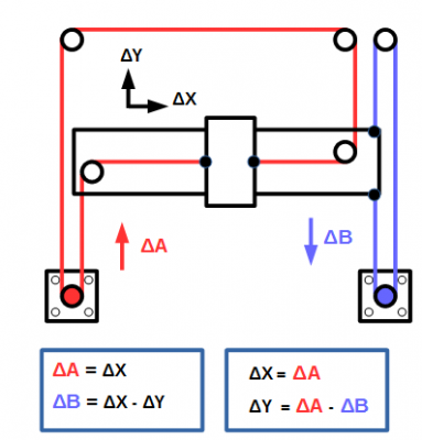
Using a configuration like the one below, the red belt (A) is kept constant in length like in CoreXY, and the blue belt (B ) is simpler.
Maybe there is something that I am missing.
The benefits I see are:
- Shorter B belt and fewer pulleys.
- Avoid the criss-cross pattern, so the belts are separated. So there is no need to make 2 heights for the belts.
The drawbacks I can see are:
- The Y movement may be less even/smooth/stable because the belt only pulls from one side.
It seems to me that it may work, I made a fast prototype and its seems ok. I am going to make new printed pieces for this configuration to see better if I am wrong.
Edited 1 time(s). Last edit at 08/31/2016 04:44PM by felipe.
|
Re: criss-cross pattern needed? August 31, 2016 01:14PM |
Registered: 7 years ago Posts: 558 |
I'm not so sure your design is a CoreXY anymore. With your design your Y movement is just the blue motor, and the red motor is just the X direction meaning it would just be a Cartesian setup apart from your using fixed motors and belt/pulley to handle the fixed motors. It should work, but wouldn't require the CoreXY math around positioning.
Edited 1 time(s). Last edit at 08/31/2016 01:15PM by PDBeal.
Edited 1 time(s). Last edit at 08/31/2016 01:15PM by PDBeal.
|
Re: criss-cross pattern needed? August 31, 2016 06:03PM |
Registered: 10 years ago Posts: 5 |
Yes, maybe this proposed arrangement cannot be called CoreXY anymore.
I think that what is important is to see if it offers any improvement.
The idea of CoreXY is good because keeps the motors away from the moving axis; therefore reducing inertia and thus, being able to get higher accelerations.
With this approach, you may get the same benefit and also reduce the length of one belt. But maybe it is not worth it.
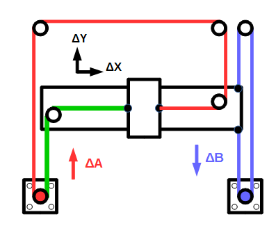
Nevertheless, the equations are not independent. If you move motor B, you get a movement in Y, but also in X. This is because the belt distance from the motor to the attaching point remains constant (I marked in green in the picture). Also the belt distance from the motor to the other attaching point (in red) remains constant.
But, if you move motor A, you just move on the X axis.
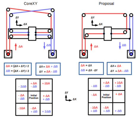
If I am not wrong, the kinetic equations compared to the CoreXY are shown in the following picture
At the bottom of the picture you can see what motor movements would be needed to move from a initial point to any of the 8 directions.
As a drawback I can see that the diagonal movement is not balanced, specially when you move in the (+x,+y) direction, you need to move motor A two times faster than motor B. Maybe that is not convenient.
Edited 2 time(s). Last edit at 08/31/2016 06:32PM by felipe.
|
Re: criss-cross pattern needed? September 01, 2016 03:32AM |
Registered: 9 years ago Posts: 125 |
One flaw that I see with your design is that as you tighten the X belt you will put a constant sideways (tilting) load on the X axis and with that on the Y movement system creating additional resistance and wear.
This could be mitigated by having the Y motor also drive the left side of the X axis (through a shaft, for example, think Ultimaker) or having another motor there.
Edited 3 time(s). Last edit at 09/01/2016 03:35AM by Mikk36.
This could be mitigated by having the Y motor also drive the left side of the X axis (through a shaft, for example, think Ultimaker) or having another motor there.
Edited 3 time(s). Last edit at 09/01/2016 03:35AM by Mikk36.
|
Re: criss-cross pattern needed? September 01, 2016 03:18PM |
Registered: 8 years ago Posts: 153 |
Quote
Mikk36
One flaw that I see with your design is that as you tighten the X belt you will put a constant sideways (tilting) load on the X axis and with that on the Y movement system creating additional resistance and wear.
This could be mitigated by having the Y motor also drive the left side of the X axis (through a shaft, for example, think Ultimaker) or having another motor there.
There is no inherent flaw, the flaw would be in the specific implementation. Any linear motion system of sufficient rigidity could easily resist the force from the belt tension.
|
Re: criss-cross pattern needed? September 01, 2016 05:36PM |
Registered: 8 years ago Posts: 13 |
Quote
n8bot
Quote
Mikk36
One flaw that I see with your design is that as you tighten the X belt you will put a constant sideways (tilting) load on the X axis and with that on the Y movement system creating additional resistance and wear.
This could be mitigated by having the Y motor also drive the left side of the X axis (through a shaft, for example, think Ultimaker) or having another motor there.
There is no inherent flaw, the flaw would be in the specific implementation. Any linear motion system of sufficient rigidity could easily resist the force from the belt tension.
Then what about H-bot? it only has 1 plane, no criss-cross, 1 belt, easy belt tension, simplicity. Only downside is longer belt then.
|
Re: criss-cross pattern needed? September 01, 2016 08:57PM |
Registered: 8 years ago Posts: 153 |
Quote
PvtPrivate
Quote
n8bot
Quote
Mikk36
One flaw that I see with your design is that as you tighten the X belt you will put a constant sideways (tilting) load on the X axis and with that on the Y movement system creating additional resistance and wear.
This could be mitigated by having the Y motor also drive the left side of the X axis (through a shaft, for example, think Ultimaker) or having another motor there.
There is no inherent flaw, the flaw would be in the specific implementation. Any linear motion system of sufficient rigidity could easily resist the force from the belt tension.
Then what about H-bot? it only has 1 plane, no criss-cross, 1 belt, easy belt tension, simplicity. Only downside is longer belt then.
I'm not sure if that statement was directed at me, because it seems we agree... this is exactly how the mark-forged printers are setup, is it not?
|
Re: criss-cross pattern needed? September 01, 2016 09:29PM |
Registered: 10 years ago Posts: 7 |
|
Re: criss-cross pattern needed? September 02, 2016 03:07PM |
Registered: 8 years ago Posts: 153 |
Quote
FrankPropaneTank
Not quite, if memory serves this is the MarkForged Mark 1 belt system:
Right. Kinematics are the same, no? The belt path is just slightly different.
[edit] Oh I see the confusion. I was referring to the original proposal diagram being similar to the markforged, not the single-belt hbot (not familiar with this)
Edited 1 time(s). Last edit at 09/02/2016 03:08PM by n8bot.
|
Re: criss-cross pattern needed? September 02, 2016 04:42PM |
Registered: 10 years ago Posts: 5 |
|
Re: criss-cross pattern needed? September 05, 2016 11:26PM |
Registered: 10 years ago Posts: 15 |
|
Re: criss-cross pattern needed? September 08, 2016 01:37PM |
Registered: 8 years ago Posts: 3,525 |
Quote
n8bot
Quote
Mikk36
One flaw that I see with your design is that as you tighten the X belt you will put a constant sideways (tilting) load on the X axis and with that on the Y movement system creating additional resistance and wear.
This could be mitigated by having the Y motor also drive the left side of the X axis (through a shaft, for example, think Ultimaker) or having another motor there.
There is no inherent flaw, the flaw would be in the specific implementation. Any linear motion system of sufficient rigidity could easily resist the force from the belt tension.
@mikk36 - or reciprocated by going around the x and y axis on the right and therefore be a proper corexy mechanism.
@n8bot - But surely this is one of the real benefits of corexy you don't need or want massive rods and bearings. The reciprocating nature of the belts means the x axis is held orthogonal to the y axis with modest sized linear guides, and importantly balanced belt tension on a and b belts. That's why it's fast and accurate, it's lightweight enough to do both. On my corexy the x axis will "bend" relative to the y axis if the belt tension is unequal, it's not so it doesn't matter that this give exists in the linear guides, they are incomplete without the belts.
The problem with the proposed scheme is that the y axis will be rotated anticlockwise as viewed from above under belt tension. So whilst it looks good you might as well put the x motor on the x axis and have a nice short simple belt but will require big heavy rods and bearings and you'll lose the speed you wanted in the first place.
Corexy is much more clever than it gets credit for, and whilst I'd love to see someone improve on it, I don't think this is it - it looks good on paper but....
Simon Khoury
Co-founder of [www.precisionpiezo.co.uk] Accurate, repeatable, versatile Z-Probes
Published:Inventions
|
Re: criss-cross pattern needed? September 08, 2016 06:11PM |
Registered: 8 years ago Posts: 153 |
Quote
DjDemonD
Quote
n8bot
Quote
Mikk36
One flaw that I see with your design is that as you tighten the X belt you will put a constant sideways (tilting) load on the X axis and with that on the Y movement system creating additional resistance and wear.
This could be mitigated by having the Y motor also drive the left side of the X axis (through a shaft, for example, think Ultimaker) or having another motor there.
There is no inherent flaw, the flaw would be in the specific implementation. Any linear motion system of sufficient rigidity could easily resist the force from the belt tension.
@mikk36 - or reciprocated by going around the x and y axis on the right and therefore be a proper corexy mechanism.
@n8bot - But surely this is one of the real benefits of corexy you don't need or want massive rods and bearings. The reciprocating nature of the belts means the x axis is held orthogonal to the y axis with modest sized linear guides, and importantly balanced belt tension on a and b belts. That's why it's fast and accurate, it's lightweight enough to do both. On my corexy the x axis will "bend" relative to the y axis if the belt tension is unequal, it's not so it doesn't matter that this give exists in the linear guides, they are incomplete without the belts.
The problem with the proposed scheme is that the y axis will be rotated anticlockwise as viewed from above under belt tension. So whilst it looks good you might as well put the x motor on the x axis and have a nice short simple belt but will require big heavy rods and bearings and you'll lose the speed you wanted in the first place.
Corexy is much more clever than it gets credit for, and whilst I'd love to see someone improve on it, I don't think this is it - it looks good on paper but....
What you say is true only of a poorly designed mechanism. See markforged printers for proof that this arrangement works. All you have to do is design the system to work sufficiently, and part of that is rigidity. If, for some reason you are obsessed with saving weight, like, if your printer will be flying on an aircraft or be taken to space, I could see why you might opt for a lighter structure with a corexy belt path... but here on earth, the proposed design works and has been proven.
Edited 1 time(s). Last edit at 09/08/2016 06:12PM by n8bot.
|
Re: criss-cross pattern needed? September 09, 2016 02:33AM |
Registered: 8 years ago Posts: 3,525 |
The markforged design works but not the OP's schematic.
I'm not obsessed with saving weight for any exotic purposes, only to avoid over-engineering and over building a machine. I am not in the slow, steady, heavy camp. I like deltas and corexys as they are lighter and faster. The original schematic wouldn't work unless you had big rods or large linear rails to prevent twisting.
My point is that you chose corexy because you want a lighter mechanism, to print faster. Otherwise why bother? Other easier to build, simpler, more reliable ways to move an axis exist. Such as cartesian axes with stacked motors.
Edited 1 time(s). Last edit at 09/09/2016 03:48AM by DjDemonD.
Simon Khoury
Co-founder of [www.precisionpiezo.co.uk] Accurate, repeatable, versatile Z-Probes
Published:Inventions
Sorry, only registered users may post in this forum.


 , all force are come from right hand side. This will cause twisting force to the structure and make right hand side move more than left hand side.