Overengineered CoreXY
Posted by anvoice
|
Re: Overengineered CoreXY January 29, 2017 12:59PM |
Registered: 7 years ago Posts: 249 |
For CoreXY with linear guides, the red piece can be a thick "U" shape, with the top of the U facing front, and the belt crossing in the back.
Reference: [forums.reprap.org]
If your concerned about the CoreXY stage (red thing) remaining flat, and the arms of the U twisting, forget I even mentioned it. Just like placing the CoreXY inside the frame instead of on top. LOL
Reference: [forums.reprap.org]
If your concerned about the CoreXY stage (red thing) remaining flat, and the arms of the U twisting, forget I even mentioned it. Just like placing the CoreXY inside the frame instead of on top. LOL
|
Re: Overengineered CoreXY January 29, 2017 02:45PM |
Registered: 8 years ago Posts: 1,671 |
Quote
the_digital_dentist
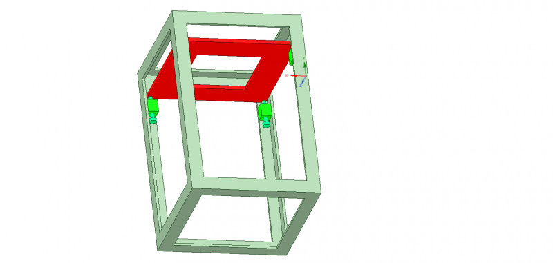
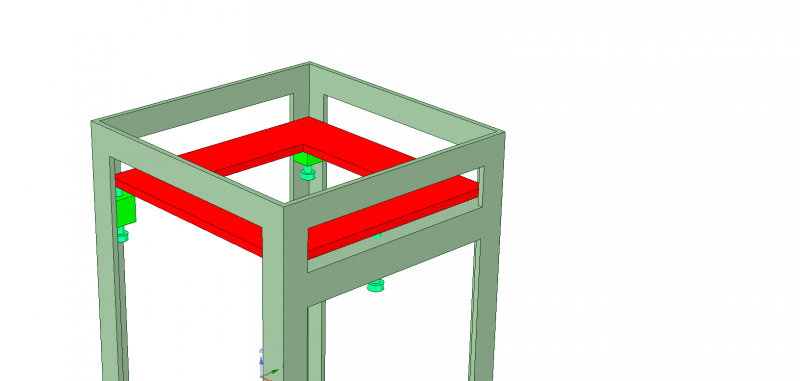
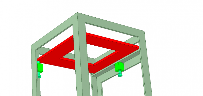
This is what I am thinking would make using a steel frame pretty easy. The XY stage (red) rests on leveling adjusters either welded or screwed into the frame (I'd screw them in):
The only thing in the machine that needs to be accurately aligned is the XY plane relative to the Z axis- the guide rails must be orthogonal, and the bed parallel to the XY plane- via the usual bed leveling system. The frame can be out of square and it doesn't matter as long as the XY and Z orthogonality can be adjusted and the bed can be leveled. If you used 3 point mount (pitch and roll adjustments), you could bolt the Z axis into the frame then just adjust the XY stage pitch and roll to ensure orthogonality, though having some adjustment capability on the Z axis would probably be a good idea too, depending on how it is made and on whether you can count on it maintaining rail to rail parallelism when you bolt it into the frame.
Leveling things accurately with 4 screws is a problem as we have seen with many poorly conceived print bed levelers. Using 3 point leveling would require adding a cross bar on one side of the frame for the XY roll adjuster.
Fitting the XY stage into the frame as I have drawn it would require removing a couple of the levelers. If you opened the top of the frame you could make it so the XY stage can just drop in from above and sit on the levelers. That would make servicing and swapping the XY stage into another frame pretty easy, and theoretically, let you put the XY stage back without having to make any adjustments.
You could add more adjusters above the XY stage to tighten down as clamps so it doesn't vibrate or shift when transported, or do something similar to my CoreXY bed levelers with one point fixed, one leveler in a slot, and the third free to slide in XY, and use springs (or clamps) to hold it down.
Good advice, some hifi stands come setup(usually 4 spikes) like that for top shelf.
Edited 2 time(s). Last edit at 01/29/2017 02:49PM by MechaBits.
|
Re: Overengineered CoreXY January 29, 2017 02:55PM |
Registered: 11 years ago Posts: 5,780 |
Yeah, based on my distant past experience with hi-fi nuts, most don't understand the difference between 4 points and 3 either.
Ultra MegaMax Dominator 3D printer: [drmrehorst.blogspot.com]
Ultra MegaMax Dominator 3D printer: [drmrehorst.blogspot.com]
|
Re: Overengineered CoreXY January 29, 2017 04:12PM |
Registered: 8 years ago Posts: 1,671 |
|
Re: Overengineered CoreXY January 29, 2017 05:23PM |
Registered: 9 years ago Posts: 238 |
|
Re: Overengineered CoreXY January 29, 2017 05:29PM |
Registered: 9 years ago Posts: 238 |
What do you mean by floating linear guide in this case? It will be bolted down at both ends, but I don't see how to make it less "floating" since it'll have to bridge the Y axis.Quote
Dutch_Razor
Also a note on the X axis, you have a floating linear guide there which does not create a stiff gantry. For linear guides, a stiff gantry can even out errors in the individual linear guides, so I would personally go for a tooling plate the width of the Y carriages, then mount the guide on there.
|
Re: Overengineered CoreXY January 29, 2017 10:27PM |
Registered: 11 years ago Posts: 5,780 |
Quote
anvoice
Thanks for the detailed advice! I'll definitely revise my design with that in mind.
Do you think the levelers for the XY stage are necessary? As you mention as long as XY is orthogonal to Z, it's fine. Wouldn't it also make sense to fine-adjust Z relative to XY?
As long as you can align the Z axis orthogonal to the XY plane, it doesn't matter which of them is adjustable.
Ultra MegaMax Dominator 3D printer: [drmrehorst.blogspot.com]
|
Re: Overengineered CoreXY January 30, 2017 01:21PM |
Registered: 11 years ago Posts: 1,049 |
I don't understand the forces involved here REQUIRING Steel construction?
and welding?
Fine cabling, or strap cross bracing, corner gussets --- can make frame rock solid.
Is it that you have lots of steel around?
and just like to weld?
Jigging up in fixture and match drilling for close tolerance fasteners --- easy!
A quick lookup 2 x 2 ft plate -- 1/4 inch -- steel $65 -- Aluminum $75
There will be many connections between frame / plate to extruder tip to introduce
a bunch of inaccurate toleances?
3D printer that can be used as a mine shaft brace?

|
Re: Overengineered CoreXY January 30, 2017 02:03PM |
Registered: 11 years ago Posts: 5,780 |
Steel angle iron is probably a lot cheaper than properly sized t-slot aluminum extrusions, and welding a frame together would certainly guarantee some rigidity (compared to 3D printing plastic corners for too small t-slot extrusions).
Ultra MegaMax Dominator 3D printer: [drmrehorst.blogspot.com]
Ultra MegaMax Dominator 3D printer: [drmrehorst.blogspot.com]
|
Re: Overengineered CoreXY January 30, 2017 04:11PM |
Registered: 7 years ago Posts: 94 |
This is a very Intresting thread. As I have similar plans. Although larger format and in a different way.
I Agree with alot, and disagree with welding.
It introduces to much heat and warps badly. Solutions mentioned by DD is very valid.
Although, its possible to weld brackets to each part. Then matchdrill and fit together with pressfitted
mashine screws. There are several ways to do this with some adjustability. But requires care and are not
easily reversed, if needed. Riveting is a very good option too. But requires the correct tools to be properly done.
Steel is a good vibration "eater" Mild steel is better than harder alloys. Cast iron is best. But is not cheap or
easily available.
Aluminum is good in many ways. But is a good vibration transporter.
To get flat surface milling is fairly good. But warps material abit. Grinding is better.
It's a lot more effort. But lapping only take elbow grease, gritpaper. Gives a good exercise and produce a better
result than grinding. Flat surface and you are set.
I Agree with alot, and disagree with welding.
It introduces to much heat and warps badly. Solutions mentioned by DD is very valid.
Although, its possible to weld brackets to each part. Then matchdrill and fit together with pressfitted
mashine screws. There are several ways to do this with some adjustability. But requires care and are not
easily reversed, if needed. Riveting is a very good option too. But requires the correct tools to be properly done.
Steel is a good vibration "eater" Mild steel is better than harder alloys. Cast iron is best. But is not cheap or
easily available.

Aluminum is good in many ways. But is a good vibration transporter.
To get flat surface milling is fairly good. But warps material abit. Grinding is better.
It's a lot more effort. But lapping only take elbow grease, gritpaper. Gives a good exercise and produce a better
result than grinding. Flat surface and you are set.

|
Re: Overengineered CoreXY January 30, 2017 04:24PM |
Registered: 9 years ago Posts: 238 |
Quote
SatorCodex
But lapping only take elbow grease, gritpaper. Gives a good exercise and produce a better
result than grinding. Flat surface and you are set.
Thanks, I learned something new. I'd definitely be willing to give that a go, though probably on a machined surface as otherwise it'll likely take forever. There happens to be a service with a large mill around so I'll have the top of my steel angle milled flat first.
As far as welding goes, it seems like the easiest solution. I don't see finding a lot of joining brackets/corners for the steel angle as easily or making it as rigid as a welded structure.
Edited 2 time(s). Last edit at 01/30/2017 04:42PM by anvoice.
|
Re: Overengineered CoreXY January 30, 2017 04:53PM |
Registered: 7 years ago Posts: 2 |
Quote
anvoice
What do you mean by floating linear guide in this case? It will be bolted down at both ends, but I don't see how to make it less "floating" since it'll have to bridge the Y axis.Quote
Dutch_Razor
Also a note on the X axis, you have a floating linear guide there which does not create a stiff gantry. For linear guides, a stiff gantry can even out errors in the individual linear guides, so I would personally go for a tooling plate the width of the Y carriages, then mount the guide on there.
Most manufacturers recommend attaching a linear guide rail to a block/plate, then measuring if the linear guide is straight, and adjusting the fastening bolt accordingly. Apperently due to the way they are made they aren't really guarateed to be straight out of the box.
|
Re: Overengineered CoreXY January 30, 2017 05:09PM |
Registered: 7 years ago Posts: 94 |
I know what you mean.Quote
anvoice
Quote
SatorCodex
But lapping only take elbow grease, gritpaper. Gives a good exercise and produce a better
result than grinding. Flat surface and you are set.
Thanks, I learned something new. I'd definitely be willing to give that a go, though probably on a machined surface as otherwise it'll likely take forever. There happens to be a service with a large mill around so I'll have the top of my steel angle milled flat first.
As far as welding goes, it seems like the easiest solution. I don't see finding a lot of joining brackets/corners for the steel angle as easily or making it as rigid as a welded structure.
I do pull out the old mig welder often.

There are always different ways and approaches to do things. Available recourses do play a big factor.
As the old saying, which way you ever turn. One wil alwaysl have the ass (butt) behind you!

That saying.
One can put effort to make a accurate frame for easy installment of the parts. Or a less accurate frame and make the effort in to putting the parts accurate.
There is just a different way to the goal.

I forgot, look up scraping. Very good way to get flat surfaces with simple hand tools. A flat surface, blue marker ink, and a cheap indicator clock, and you are good.
Very revarding, If one is a bit silly.
I hope to follow your build soon!
Edited 1 time(s). Last edit at 01/30/2017 05:10PM by SatorCodex.
|
Re: Overengineered CoreXY January 30, 2017 05:11PM |
Registered: 8 years ago Posts: 1,671 |
I figure the people who make hifi stands in bulk have the welding sorted, its very neat looks like a machine did it, just checked it to see if its true(yup), but mounts are adjustable, so I doubt I will ever drill it to mount anything even though there might be a slight improvement. Looks like I might have to figure a belt solution if I want the full height but either way i'll be happy. Planning on not fully supporting these cheap black rails(noise is really reduced over 8mm rods) So I pressed on them to see how much sag was in there, I can only deflect it by about 1mm but doubt that will effect things when in motion.
|
Re: Overengineered CoreXY January 30, 2017 11:16PM |
Registered: 9 years ago Posts: 238 |
Curious about what people are using for pulleys: I see some smooth pulleys on ebay, but the max bore diameter is 5mm. Is it fine to use 608 bearings directly, perhaps with some plates on the sides to prevent the belt from sliding? I feel that the 8mm bore will be better for stability.
Belts are another issue altogether: there's a ton out there, including Kevlar reinforced, etc. I'm thinking of going with steel core gt2 belt and seeing how that goes.
Belts are another issue altogether: there's a ton out there, including Kevlar reinforced, etc. I'm thinking of going with steel core gt2 belt and seeing how that goes.
|
Re: Overengineered CoreXY January 31, 2017 12:55AM |
Registered: 11 years ago Posts: 5,780 |
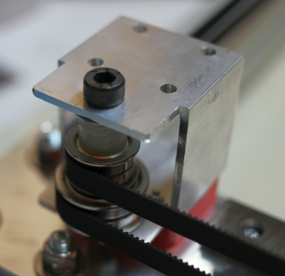
I'm partial to F608zz bearings stacked to make 11 mm wide flanged pulleys- no plates necessary. They are close to the SDP/SI recommended diameter for smooth pulleys in contact with belt teeth, they accommodate 9 or 10 mm wide belt (which will stretch less than 6 mm wide belt and costs only pennies more), and they are cheap.
The larger pulley is made from F6903 bearings.
Ultra MegaMax Dominator 3D printer: [drmrehorst.blogspot.com]
The larger pulley is made from F6903 bearings.
Ultra MegaMax Dominator 3D printer: [drmrehorst.blogspot.com]
|
Re: Overengineered CoreXY January 31, 2017 05:35AM |
Registered: 9 years ago Posts: 238 |
What about the ABEC grade of the bearings you use? Supposedly the higher grade ones have lower runout and introduce less friction. Or is that fairly insignificant?
I can find ABEC 9 grade 608ZZs but no grade information on the F609ZZs. Also some ceramic bearings which supposedly deform less under load.
Edited 1 time(s). Last edit at 01/31/2017 05:44AM by anvoice.
I can find ABEC 9 grade 608ZZs but no grade information on the F609ZZs. Also some ceramic bearings which supposedly deform less under load.
Edited 1 time(s). Last edit at 01/31/2017 05:44AM by anvoice.
|
Re: Overengineered CoreXY January 31, 2017 07:28AM |
Registered: 11 years ago Posts: 5,780 |
1) ABEC ratings of cheap bearings bearing ABEC ratings are probably a lie.
2) I don't detect any run out in my cheapo, non-ABEC rated bearings. Friction is low enough.
3) The loads presented in a 3D printer are orders of magnitude lower than the ratings of the parts, so deformation under load isn't going to be significant.
4) Ceramic bearings would be a complete waste of money in this use - you're better off investing more in the extruder and hot-end, both things that will make a real difference in the performance and reliability of the printer.
F6903zz bearings have a 17 mm bore. I printed a bushing to reduce that to 8mm. I try to limit use of 3D printed parts in my designs to spacers, belt clamps, switch mounts, and little clips to hold things in the t-slots.
I have a bunch of glass core belt in the machine right now, and the stuff is cheaply made- glass fibers are evident along the edges of the belt, and it's easy to pick up a splinter from them. If you watch the belt as it moves, it is evident that the slicing (the belt was probably sliced down from much wider belt stock) is uneven. Just yesterday I received some steel core HTD 3 belt from China and the quality appears to be much higher. We'll see how it behaves on the machine. Though I have yet to find specs comparing glass core to steel core belt, I suspect that steel core belt will stretch less than glass core belt. 5m of HTD3 steel core belt was $22, shipped.
Ultra MegaMax Dominator 3D printer: [drmrehorst.blogspot.com]
|
Re: Overengineered CoreXY January 31, 2017 08:58PM |
Registered: 9 years ago Posts: 238 |
Thanks, makes sense.
One last question for the moment: you mentioned I think that Nema23's are overboard and noisier than Nema17. I'd like to get the 0.9 degrees/step variety though, and those just don't come with a very high torque (62Ncm is the best I could find) for Nema17. Would it make sense to get the Nema23s because of the 0.9 degree/angle stepping? I'm guessing if I align everything perfectly 0.9 could very well make a large difference compared to 1.8.
One last question for the moment: you mentioned I think that Nema23's are overboard and noisier than Nema17. I'd like to get the 0.9 degrees/step variety though, and those just don't come with a very high torque (62Ncm is the best I could find) for Nema17. Would it make sense to get the Nema23s because of the 0.9 degree/angle stepping? I'm guessing if I align everything perfectly 0.9 could very well make a large difference compared to 1.8.
|
Re: Overengineered CoreXY February 17, 2017 02:07AM |
Registered: 9 years ago Posts: 238 |
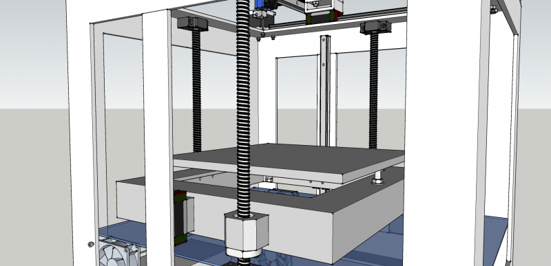
Thinking of improving on the design by using either 2 ballscrews and 4 linear guides (lead screws center on both sides and a linear guide at each corner), or 3 ballscrews and 2 linear guides for the Z axis. Any thoughts on what would be advantageous? I do hear that if choosing the latter, driving 3 screws with one motor is wiser.
|
Re: Overengineered CoreXY February 17, 2017 09:47AM |
Registered: 11 years ago Posts: 5,780 |
0.9 degree steppers can double the resolution of the machine, and they might run a little smoother than 1.8 degree steppers. I'm not sure its necessary to increase the resolution- 1.8 degree motor with a 20 tooth pulley will provide 80 step/mm. Going to 160 steps per mm sounds good, but I'm not sure you're really going to see any difference in the prints- the extruder is squirting liquid plastic out of a nozzle- once it leaves the nozzle it goes where it wants until it stiffens up. 0.9 degree per step motors will limit your maximum speed to 1/2 of what you could do with a 1.8 degree motor, and a lot of people seem to be very concerned about maximizing print speed- maybe you're one of them?
I would select the steppers after you have designed the rest of the mechanism and have some idea of its mass. The massive construction of my machine's XY mechanism seems to be served just fine by 64 oz-in 0.9 degree steppers. I'm using a NEMA-23 motor in the Z axis because that's what comes on the Rino worm drive reducer, but a NEMA-17 motor should easily be able to deliver the required torque if it's on a 30:1 reducer. NEMA-23 in the Z axis can't hurt, and the noise/vibration is unlikely to be a big problem.
I don't know that ball screws offer any real advantage over lead screws in the Z axis. Ball screw pitch/lead is typically longer than lead screw pitch/lead, so it would require higher torque from the motor (NEMA-23 to the rescue) to lift the bed and you might end up with a bed-drop problem when the power to the Z axis motor is cut. Ball screws will probably cost a lot more than lead screws unless you get lucky and find them at a scrap yard (I get lucky like that once in a while).
Two or three linear guides should be enough to keep the bed under control laterally, if you use them fully supported. If you just end-support them they aren't going to be much better than round rails.
Ultra MegaMax Dominator 3D printer: [drmrehorst.blogspot.com]
|
Re: Overengineered CoreXY February 18, 2017 06:59AM |
Registered: 9 years ago Posts: 238 |
I'm not that concerned about speed, my main issue is print quality. Although I already have some 2A 0.9 degree Nema 23 steppers as well as a couple of 68 oz-in 0.9 Nema 17 steppers that I can use for the XY. I'll go with the Nema 17's if they can pull the axes fine.
I think I'll fully support my Z linear rails, so using 4 rails per corner plus 2 ballscrews should be good enough I hope.
I think I'll fully support my Z linear rails, so using 4 rails per corner plus 2 ballscrews should be good enough I hope.
|
Re: Overengineered CoreXY February 20, 2017 09:55AM |
Registered: 8 years ago Posts: 15 |
Quote
anvoice
I'm not that concerned about speed, my main issue is print quality. Although I already have some 2A 0.9 degree Nema 23 steppers as well as a couple of 68 oz-in 0.9 Nema 17 steppers that I can use for the XY. I'll go with the Nema 17's if they can pull the axes fine.
I think I'll fully support my Z linear rails, so using 4 rails per corner plus 2 ballscrews should be good enough I hope.
I'm 1/2 through a large corexy build and thought I could share a bit. This is my 2nd attempt to make a big machine. The 1st one used round rods and was way too compliant to be of any use. So I'm reusing everything I can from the 1st one and am borrowing from Jetguy's "Big Boy" printer design . My X-Y system is a direct copy and so far seems perfect. It uses three 420mm MGN12 Hiwin rails with the X rail bolted to 1/8" x 2" aluminum bar stock from Home Depot to form a "T" beam gantry. This is much better than 1st appearances. The mild aluminum supports the rail and is very, very stiff in the Y direction. Jetguy's hand-built printers have virtually no ringing artifacts.
My Z axis is a little different. I'm using 2 rails and 4 lead-screws (rather than 3) in attempt to maximize the table size inside the frame (plus I got a good deal on them). Also the Z travel range is big -> too big really. The problem I'm having is that it is very hard to get the 2 linear rails to be parallel and true over a large travel range in the vertical axis. Mine are binding when bolted to the Z-table cross member but run freely individually. These two are not Hiwin brand but seem good enough for the slow Z-travel; they don't bind by themselves. I've tried various combinations of assembling and truing the rails and frame with no joy. No such problems with the X-Y gantry system but that is using gusset plates to hold everything square. I don't see how to do the same thing for the Z-axis. Right now I'm making an attachment using spherical bearings. I think that by giving the rail bearings some freedom in misalignment they won't bind.
So my point (yes, there is one) is that it is hard enough to get 2 rails to run parallel with each other. I sure wouldn't want to try fighting 4 of them. The 2 rails just have to hold the Z-table square to the frame in the X-Y plane. Use 3 screws hold the table level and drive them all from the bottom with a common endless belt.
Edited 1 time(s). Last edit at 02/20/2017 10:42AM by napierm.
|
Re: Overengineered CoreXY February 20, 2017 05:44PM |
Registered: 10 years ago Posts: 221 |
Hi Napierm
My system of setting up the 2 rails is to tighten one rail, hopefully straight and perpendicular etc. Then run the carriage along it tightening the other rail as you go. This has worked for me up to 1 meter. If it is not working look for the rails not being on the same plane or the carriage twisted. An option if all else fails might be to rubber mount one rail so it can move slightly. DD has a rail floating to allow for thermal expansion.
Rod
|
Re: Overengineered CoreXY February 20, 2017 07:41PM |
Registered: 11 years ago Posts: 5,780 |
Actually, my X axis rail is mounted so that the Y axis rails can move apart as the printer frame heats up and expands. It's a completely different issue from aligning two rails parallel to each other. One advantage of linear guides is that they are relatively easy to align parallel if you mount two of them on a common base plate. Then they can only be out of parallel in one dimension and that can be corrected by using one rail as the reference for the other, as you have described. It becomes more complicated when the rails are not mounted on a common base plate.
Ultra MegaMax Dominator 3D printer: [drmrehorst.blogspot.com]
Ultra MegaMax Dominator 3D printer: [drmrehorst.blogspot.com]
|
Re: Overengineered CoreXY February 21, 2017 12:29AM |
Registered: 9 years ago Posts: 238 |
Quote
napierm
So my point (yes, there is one) is that it is hard enough to get 2 rails to run parallel with each other. I sure wouldn't want to try fighting 4 of them. The 2 rails just have to hold the Z-table square to the frame in the X-Y plane. Use 3 screws hold the table level and drive them all from the bottom with a common endless belt.
Thanks for sharing your experience Napierm. I definitely see your point. I was leaning towards the 4 rail solution but now I'm going to have to consider it long and hard.
|
Re: Overengineered CoreXY February 21, 2017 08:54AM |
Registered: 8 years ago Posts: 15 |
Quote
the_digital_dentist
Actually, my X axis rail is mounted so that the Y axis rails can move apart as the printer frame heats up and expands. It's a completely different issue from aligning two rails parallel to each other. One advantage of linear guides is that they are relatively easy to align parallel if you mount two of them on a common base plate. Then they can only be out of parallel in one dimension and that can be corrected by using one rail as the reference for the other, as you have described. It becomes more complicated when the rails are not mounted on a common base plate.
Do you have a picture or drawing showing how your X axis rail is mounted on the Y axis bearing blocks? Thanks in advance.
Mark Napier
|
Re: Overengineered CoreXY February 21, 2017 11:51AM |
Registered: 11 years ago Posts: 5,780 |
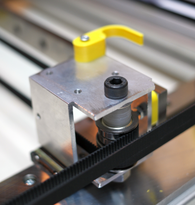
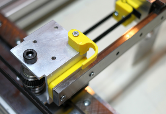
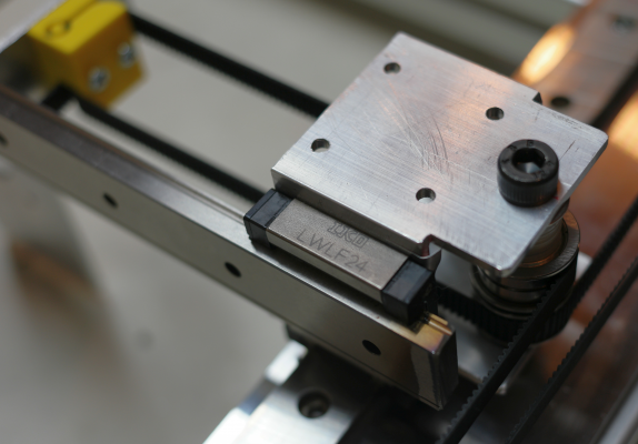
Here is the X axis. Pulleys are mounted in rectangular aluminum tubes screwed to the Y axis bearing blocks. The X axis rail attaches to those same tubes. On the left side there is an X axis bearing block screwed to the tube. On the right side there is a spacer, printed yellow in the photo, attaching the X axis rail directly to the tube through the spacer. The spacer thickness matches the height of the bearing block to help keep the Y axis pulleys lined up. And of course, the extruder carriage rides on an X axis bearing block. The belt clamp width matches the diameter of the pulleys at the ends of the X axis, so the belt segments run parallel to the X axis guide rail. When the extruder carriage is at either end of the X axis rail, the belt clamps are free to go inside the end tubes with no interferences, right up until the extruder carriage bangs into the tube.
The X axis rail is mounted the way it is because it allows the Y axis rails to separate when the machine's aluminum frame heats up and expands. The belt tension forces create some side load/torque in the Y axis linear guides, but it is well within the linear guides loading specs, so I'm not concerned about it. The other way to mount the pulleys would be to attach them to the X axis rail, but tension forces there would tend to bow the rail and maybe prevent printing straight lines parallel to the X axis. The way it is mounted, there are no forces on the X axis rail other than the friction of the extruder carriage bearing block.
Since this photo was made, the extruder carriage has been replaced with a tube (surprise!) that doesn't bend open under the belt tensile forces. The printed spacer on the right has been replaced with milled aluminum, and the Y axis limit switch bumper design has changed.
This is an experiment and if I don't like the print results I'll probably screw the X axis rail to a tube to stiffen it up, or do whatever else the print quality demands.
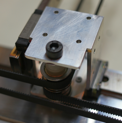
Here's the X axis pulley on the right side:
And here's the X axis pulley on the left side:
Ultra MegaMax Dominator 3D printer: [drmrehorst.blogspot.com]
|
Re: Overengineered CoreXY February 22, 2017 04:05AM |
Registered: 8 years ago Posts: 5,232 |
|
Re: Overengineered CoreXY February 23, 2017 03:26AM |
Registered: 9 years ago Posts: 238 |
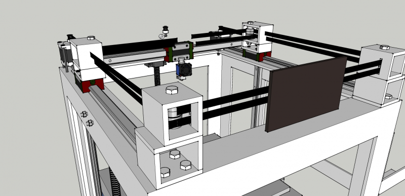
Here's a redesigned version of the printer as I have it so far. Now it uses 3 ballscrews and 2 linear guides for the Z, as well as dual 608 bearings for pulleys to accommodate 10mm belts on the XY. Haven't figured out what sort of gearbox I'll drive the Z with but I'll do a bit of research and probably manage.
Especially appreciate all of your feedback that helped make some positive changes.
Especially appreciate all of your feedback that helped make some positive changes.
Sorry, only registered users may post in this forum.
