My CoreXY build log
Posted by TE78
|
My CoreXY build log March 25, 2017 03:07PM |
Registered: 7 years ago Posts: 18 |
1st post, but been reading on here for months before registering so I could share some of what I'm up to. My name's Tim and I've been into model engineering for a few years.
This will not be a quick build as workshop time is limited, I've already been pecking away at this for over a month to get to where I am today.
For quite a while now I have had the urge to build a 3d printer, reading around and doing a bit of research I decided on a "CoreXY" style. As I understand it, the basics of this style is to create a box frame to which the linear bearings and everything else are attached. So a few weeks ago I started by deciding on the outside dimensions, 425mm x 425mm x 500mm high, with the plan that (hopefully) I will end up with a Print capacity of about a 300mm cube.
Over a year ago when I first had thought about building a 3d printer I had ordered some 400mm x 8mm rods and a bunch of 8mm linear bearings. In my research I found that many found the 8mm rods flex on larger printers, so that made me experiment with deflection and I found that I got about 0.4-0.8 mm deflection on a single 8mm rod with a highly specified weight in the centre (a box of coach bolts). So I got some 12mm rods and linear bearings for the Y axis. I plan on using 3 8mm rods for the X-axis in a "L" configuration, that should minimise deflection.
I have no fancy 3d renderings of what I am building, so that's another reason why this will be a longer build, I will be spending plenty of time thinking before hacking up metal.
So a little more on the design (such as it is). I had a few lengths of 25mm box section steel just lying around waiting to be used, so I cut 8x 375mm lengths for the stretchers top and bottom, and cut 4x 500mm lengths for the 4 uprights. I then set up a vice-stop on the mill and drilled & reamed a 8mm hole through, centred 50mm from one end in each upright. Then I drilled out one side of the 8mm hole to 16mm and then cleaned up the drilled hole with a boring bar to ensure a truly round hole (ended up being about 16.2mm) This was done so that when the whole box was assembled I would have a means of adjusting both the Y-axis bars to get them parallel and flat in relation to each other. I figured I would make bushes for these holes that could be have offset holes in them to carry the Y-axis bars.
It was at this point that I realised that I would need a way of inserting the 12mm Y-axis bars through the frame, so I enlarged 2 of the 8mm holes in the uprights to 12mm.
Then I started to weld up all the stretchers and uprights (after carefully marking each, and also drilling a few M5 holes for potential future use), this called for some thought as the process of welding introduces many stresses and it is remarkable how much it will pull and move parts. I ended up by tack welding only the very outside corners, making 2 sides and then carefully tacked on the stretchers to join the 2 sides into a cube. Then I followed a painstaking process of checking every corner with my 9" engineers square, finding the worst out-of-square culprit and placing a tack weld in the right place to pull it back into square. (it was really surprising how much the metal moves as it cools) Then I would wait until it had cooled before moving onto the next one. Lather, rinse and repeat....... This took quite a few sessions, but was really worth it to get a cubic frame that was less than 1mm out of square in any axis.
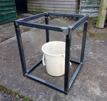
Then I made up 3 bushes that were concentric and one that was 0.35mm non-concentric (the error I measured in the holes I previously bored), fitted the arrived 12mm ground bars, and voila (bucket for scale)
Today I started thinking about making sure that the 2 bars were absolutely parallel and also flat with relation to each other. I previously was trying to get them running true in the same plane as the top of the frame, but I realised that the frame has a slight rock to it (about 0.7mm), so it struck me that the most important thing is to get both Y-axis bars true and parallel to each other, everything else can be made true in reference to the Y-axis bars.
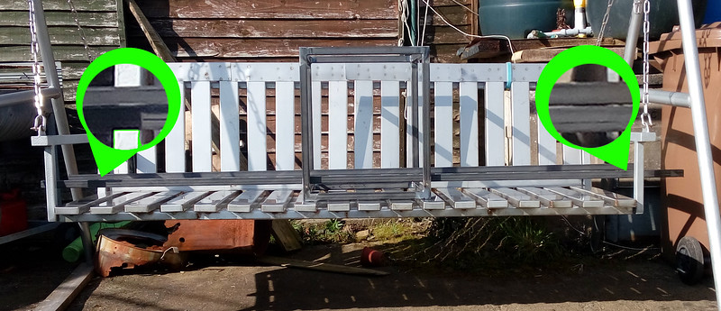
But how do you measure any runout when the 2 bars are 400mm+ apart? Then I remembered "Rollie's dad's method" and wondered if it could help in this situation. As I recalled it, Rollies dad's method involved using 2 long bars resting on the ways which would then seemingly amplify any error and make it plainly visible at the 2 ends of the long bars. So I set the frame upside down (the only long bars I had wouldn't fit in the gap above the 12mm bars) and stuck 2 6ft lengths of 25mm box section on the bars and took a few steps back. (parts magnified for clarity) I set it on the seat to prevent me having to crawl on the ground to "sight" along the bars!!
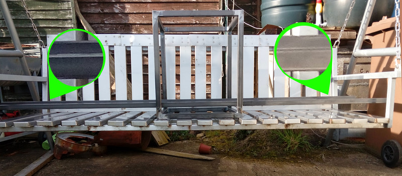
Definitely can see that there is a slight twist to the bars.(probably about 13-14mm off at the end of the long bars) So I turned up another offset bush to replace a concentric one and tried again. A little better, but not enough, so a 3rd offset bush was made with this result. Much better!!
I made up an extension for my digi-vern so I could check the distance between the 2 Y-axis bars and was very pleasantly surprised to find they were only 0.03mm out of parallel !!
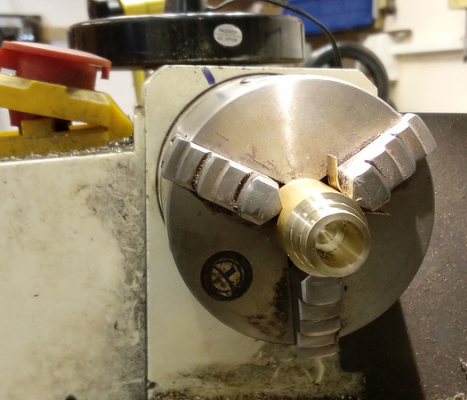
Here's the easy way I made the offset on my mini lathe, just inserted a shim between one jaw and the work.
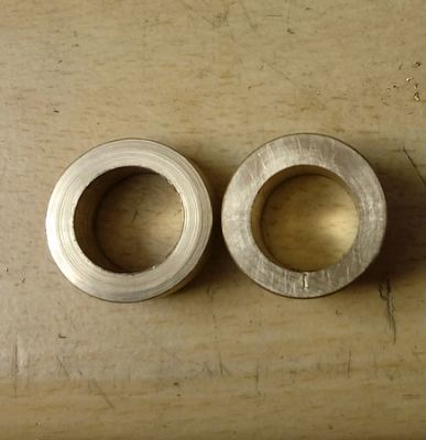
Here's an offset bush next to a concentric one
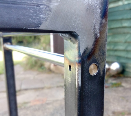
As you can see I have marked the "low" spot on the offset bush, this makes it easy to put a matching mark on the frame so that when re-assembling I can be sure they go back in the right position.
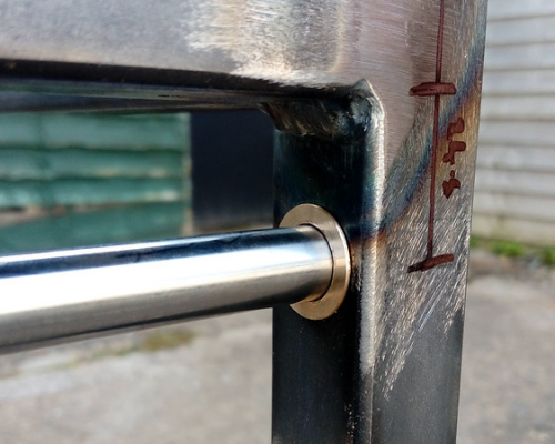
Here's a couple of close-up shots of the insert/bush in place
On this one you can see the little mark I made to indicate the "Low" point of the bush/insert
Next up will be working on the Y-axis carriage's, but I gotta order some ali bar for making those.
Stay tuned for irregular updates.
Tim
|
Re: My CoreXY build log March 27, 2017 11:08PM |
Registered: 10 years ago Posts: 211 |
|
Re: My CoreXY build log March 28, 2017 10:43AM |
Registered: 11 years ago Posts: 5,780 |
How did you manage to drill the holes in the frame so they are properly aligned and will allow your cam to position the guide rails parallel to each other? What did you use for a reference for the measurements?
I don't think the cams guarantee that you can position the rails parallel to each other. Assume the holes are perfectly aligned and if you used installed the rails without the cams they would be parallel. Now add the cams- by rotating the cams to the same position you still have parallel rails, but they are no longer parallel to the frame. That's OK. Now assume that there's some random error in the hole positions and the rails don't start parallel. Your cams allow adjustment at a specific offset from the axis of the holes, lets pick a number like 0.4mm. If the errors in the hole positions aren't both 0.4 mm, your cam can't do the job you intended.
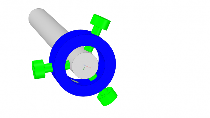
This would work because it allows any value of offset from the center (including zero) of the hole in the frame:
You have to be careful at the other end of the rail to allow the end of the rail a little room to tilt otherwise you may cause the rail to flex when you make adjustments to the screws.
These sorts of mechanical alignment issues are always tricky. I've considered building a delta printer but I can't figure out any acceptable (to me) way to ensure that the vertical frame pieces are in alignment.
Edited 4 time(s). Last edit at 03/28/2017 11:13AM by the_digital_dentist.
Ultra MegaMax Dominator 3D printer: [drmrehorst.blogspot.com]
|
Re: My CoreXY build log March 28, 2017 12:29PM |
Registered: 7 years ago Posts: 18 |
Quote
the_digital_dentist
How did you manage to drill the holes in the frame so they are properly aligned and will allow your cam to position the guide rails parallel to each other? What did you use for a reference for the measurements?
I drilled the holes before I welded the frame up. I set up a vice-stop in my mill so that each upright would be positioned the same place, and then using an edge finder on both sides I was able to get the exact centre of the uprights. I drilled through at 7.7 mm, then reamed to 8mm on all 4 uprights. Then I enlarged to 12mm reamed through on 2 uprights (the front ones) and then enlarged the inside-facing holes to 16mm (and then bored with a boring bar to ensure precise "roundness" so that the bushes would fit better and be able to rotate if needed). In all these operations I did not move any of the mill's axis' apart from the Z.
Then once the frame was welded up (as square as I could make it, less than 1mm out in any direction) I initially measured from the ends of the frame to the edges of the inner-facing 16mm holes (which were precisely bored to the same diameter) using a digi-vernier. From these measurements I was able to measure that three of the holes were the same distance down from the top of the frame (+/-0.1mm) and the 4th was 0.28mm lower. I also measured the distance between the left and right holes at the front, and then the same at the back, (this time using a steel rule, my digi-vernier wouldn't stretch) and the 2 sides were within 0.3mm of parallel.(as it turned out, they were pretty much dead on when I installed the rails and measured with my extended digi-vern)
You are absolutely right, it was only as a result of my measurements that I could know what offset was needed. And it was only at that point I realised that I hadn't thought about making sure the 2 rails were not just parallel, but co-planar (I think that's the right term?). Hence I had to make a total of 3 offset bushes. I also made an extension for my digi-vernier so I could accurately measure the distance between the 2 Y-axis rails and they were parallel to 0.01mm (this was not complete chance, but was mainly down to the accuracy of the initial drilling and boring in the mill before welding up)Quote
I don't think the cams guarantee that you can position the rails parallel to each other. Assume the holes are perfectly aligned and if you used installed the rails without the cams they would be parallel. Now add the cams- by rotating the cams to the same position you still have parallel rails, but they are no longer parallel to the frame. That's OK. Now assume that there's some random error in the hole positions and the rails don't start parallel. Your cams allow adjustment at a specific offset from the axis of the holes, lets pick a number like 0.4mm. If the errors in the hole positions aren't both 0.4 mm, your cam can't do the job you intended.
A similar method was pointed out to me by someone else, and to be honest I wish I'd have thought of it before. If you had one of those 3-screw mounting bushes on each end of the rail you would have fantastic adjustment for level/parallel/co-planar. If I was building again I would definitely use that method, the only reasons I don't adapt this build to use it is that 1, It seems to be working out as it is, and 2, I would lose too much on the Y-axis (I'm already pushing it to get a 300mm x 300mm build area out of a 375mm usable rail length)Quote
This would work because it allows any value of offset from the center (including zero) of the hole in the frame:
Quote
You have to be careful at the other end of the rail to allow the end of the rail a little room to tilt otherwise you may cause the rail to flex when you make adjustments to the screws.
That's true, I also have to add a grub screw to the front bushes to secure the rails in place. While I'm waiting on the Ali for the Y to X axis carriages I am working on the mounts for the CoreXY steppers, Originally I wanted to have the steppers inside the frame, but that would either lose me too much Y-axis travel or would result in a more convoluted belt path. So I will be mounting the steppers on the outside of the frame. I plan to have the 2 belts running one above the other, ie not crossing over.
Tim
|
Re: My CoreXY build log March 28, 2017 03:30PM |
Registered: 11 years ago Posts: 5,780 |
Now you're finding out the problem with designing and building the frame before the other details are worked out. I prefer to start on the inside and work my way outward. Even at that there's room for errors to creep in. My latest build didn't account for the offset from center of the hotend, and as a result I can't quite print all the way to one edge of my bed plate.
When you start from the frame, unless you build it grossly oversized, you won't be able to print as large as you intended.
Ultra MegaMax Dominator 3D printer: [drmrehorst.blogspot.com]
When you start from the frame, unless you build it grossly oversized, you won't be able to print as large as you intended.
Ultra MegaMax Dominator 3D printer: [drmrehorst.blogspot.com]
|
Re: My CoreXY build log March 28, 2017 04:01PM |
Registered: 7 years ago Posts: 18 |
Yea, there's no substitute for experience, which I don't have any in building 3d printers!! But I'm reading as much as I can find and trying to learn from the experience of others.
I have thought about the hotend being offset, and how the X-axis carriage size reduces the working range by the same amount of it's dimensions. I will wait until I've built the X-axis carriage before starting on the Z-axis and print-bed assembly because I want the centre of the print-bed to align with where the hotend would be in the centre of it's X & Y travel.
I suppose the converse is true as well, when you start with the inside you are in danger of building it oversized!!!
My goal was to have the overall size of no greater than 500mm cubed, and even with having to mount the steppers outside the main frame I will still be within my goal. Maybe it will turn out better to have the steppers outside the main frame, I'm intending to enclose the frame, so if I decide to print with ABS I can heat the print area and keep the steppers cooler without cooling the print area. So every cloud has a silver lining.
Tim
I have thought about the hotend being offset, and how the X-axis carriage size reduces the working range by the same amount of it's dimensions. I will wait until I've built the X-axis carriage before starting on the Z-axis and print-bed assembly because I want the centre of the print-bed to align with where the hotend would be in the centre of it's X & Y travel.
Quote
When you start from the frame, unless you build it grossly oversized, you won't be able to print as large as you intended.
I suppose the converse is true as well, when you start with the inside you are in danger of building it oversized!!!
My goal was to have the overall size of no greater than 500mm cubed, and even with having to mount the steppers outside the main frame I will still be within my goal. Maybe it will turn out better to have the steppers outside the main frame, I'm intending to enclose the frame, so if I decide to print with ABS I can heat the print area and keep the steppers cooler without cooling the print area. So every cloud has a silver lining.
Tim
|
Re: My CoreXY build log March 28, 2017 06:04PM |
Registered: 7 years ago Posts: 94 |
Quote
the_digital_dentist
. I've considered building a delta printer but I can't figure out any acceptable (to me) way to ensure that the vertical frame pieces are in alignment.
Hm.. Think about it.
A plumb Bob will do the job. Together with a jig/fixture.
Do it sound crude? Think about it.
|
Re: My CoreXY build log March 28, 2017 06:10PM |
Registered: 7 years ago Posts: 94 |
|
Re: My CoreXY build log April 24, 2017 08:02AM |
Registered: 7 years ago Posts: 18 |
A little more progress to report.
I've made up a couple of Stepper Motor mounts to be welded on to the frame, but I'm glad that I didn't weld them on as I've changed my mind on how I'm routing the belts ( I may change it again as the project progresses )
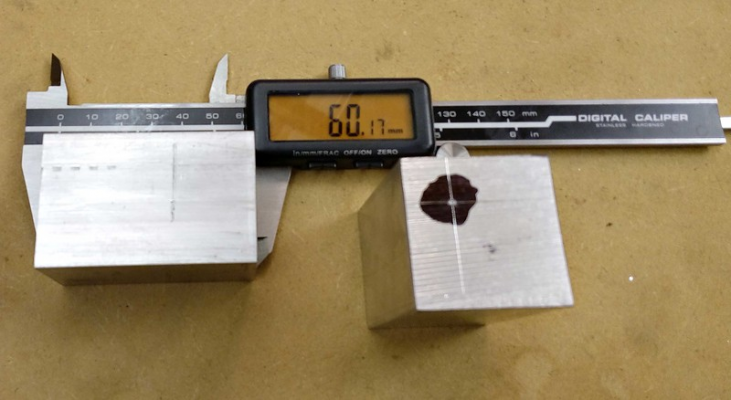
But I acquired a short length of 37mm square ali bar which I hacked off a couple of shorter lengths to make the Y-Axis ( I think ) carriages, and made a centre-pop mark for boring out to accept the 12mm linear bearings.
I then mounted it off-centre in the 4-jaw chuck in the lathe. I used a "wiggler" in the tailstock with the point in the centre-pop, then put a DTI on the shaft of the wiggler and adjusted until I had less than 0.1mm runout. Then it was just a case of drilling out to 18mm, then swapping to a boring bar to bore out to a nice tight-sliding fit for the bearings.
Then, putting the bearings into both carriages, and sliding a 12mm rod into them I mounted both end-to-end in the mill, supported by the 12mm bar, then skimmed each face in turn to make sure that each face is parallel to the bore.
Then I drilled and reamed the 8mm holes for the x-axis bars, which ended up being on 48mm centres, so 40mm between inner edges of the bars.
I couldn't help myself and assembled the bits together, it moves really easily with no racking.
There's still a lot to be done to these y-axis carriages, next up will be milling off some on the underside for mounting idler-pulleys for the belts, and also drilling and tapping some holes for screws to secure the bearings and also the 8mm x-axis bars.
Once all the work is done on the y-axis carriages I will see where more material can be milled off to lighten it further.
Thanks for watching,
Tim
|
Re: My CoreXY build log April 24, 2017 08:05PM |
Registered: 10 years ago Posts: 770 |
|
Re: My CoreXY build log April 24, 2017 10:44PM |
Registered: 11 years ago Posts: 5,780 |
Are the X axis rails locked down in the Y axis bearing blocks somehow? If not, when you apply belt tension the Y axis bearing blocks will try to move toward each other and the mechanism may bind.
Ultra MegaMax Dominator 3D printer: [drmrehorst.blogspot.com]
Ultra MegaMax Dominator 3D printer: [drmrehorst.blogspot.com]
|
Re: My CoreXY build log April 25, 2017 01:30AM |
Registered: 7 years ago Posts: 18 |
Quote
Nice and chunky where it matters. I like it!
Thanks, but it will get slimmed down once all the essential engineering is done, corners will be either rounded or bevelled, all to shave the weight down as much as possible.
Quote
the_digital_dentist
Are the X axis rails locked down in the Y axis bearing blocks somehow? If not, when you apply belt tension the Y axis bearing blocks will try to move toward each other and the mechanism may bind.
They will be, I haven't drilled and tapped for a grub screw on each rail yet, but it's on the "to-do" list.
Tim
Edited 1 time(s). Last edit at 04/25/2017 01:37AM by TE78.
|
Re: My CoreXY build log April 25, 2017 11:41AM |
Registered: 8 years ago Posts: 3,525 |
Quote
the_digital_dentist
I've considered building a delta printer but I can't figure out any acceptable (to me) way to ensure that the vertical frame pieces are in alignment.
You make the bottom triangle, ensuring the distance between the corners and the horizontals are all the same, tighten it all up. Make the top triangle to the same dimensions. It helps to build it on the tooling plate before it gets cut into a circular bed. Insert the uprights and then use a square to make sure they are at 90 degrees to the horizontals, tighten the bolts. Add the top triangle and then remeasure the distance between the verticals at the top and bottom on all three sides. Mine are all within 0.1mm over a 330mm horizontal and 1m verticals.
If that's not enough consider turnbuckles and wire, to tweak the frame even closer to perfect.
Edited 1 time(s). Last edit at 04/25/2017 11:44AM by DjDemonD.
Simon Khoury
Co-founder of [www.precisionpiezo.co.uk] Accurate, repeatable, versatile Z-Probes
Published:Inventions
|
Re: My CoreXY build log May 07, 2017 01:19PM |
Registered: 7 years ago Posts: 18 |
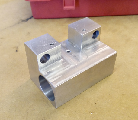
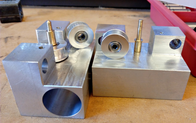
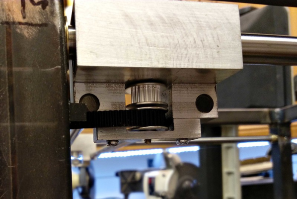
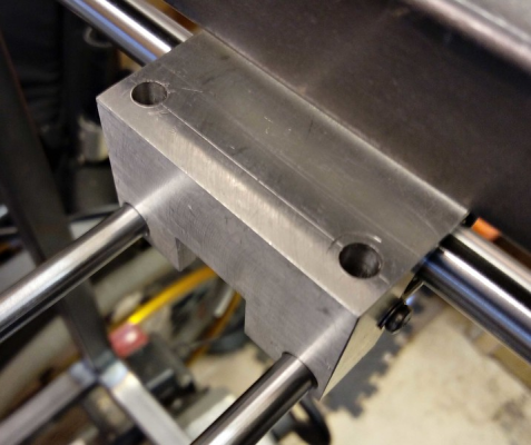
A little more progress made today. I started working on the Y-Carriage blocks to whittle them down a bit for mounting the bearing-pulleys for the belts to run round. So I milled off a "T" section, drilled for tapping M3 for mounting the bearing-pulleys (the centre hole) and drilled two holes 15mm either side so that I can make a little bracket to fix the top side of the pulleys.
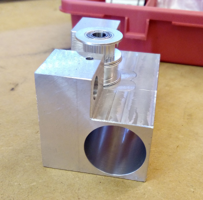
Another view with the bearing-pulleys put in place,
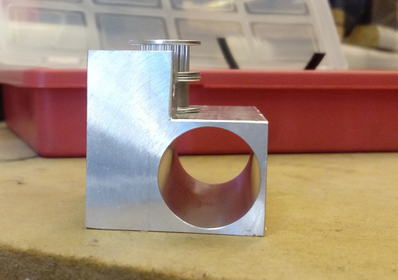
End-on view,
I reckon that, compared to the plain Ali' blanks, these are now at least half the weight, and I'm not done yet!! I still have a fair bit more I can mill off, but any major milling will wait until near completion as it gets hard to accurately hold in the vice when you don't have a couple of the original squared faces untouched.
Onwards and sideways,
Tim
|
Re: My CoreXY build log May 08, 2017 01:05PM |
Registered: 7 years ago Posts: 18 |
I got a little more done today (emphasis on "little"),
I tapped the 3 holes on each carriage M3. Then I made the pin that will screw in to hold the ball-raced pulleys. The plain pulley has a bore, or rather, the bearing in the plain pulley has a bore of 3mm, whereas the bearing in the toothed pulley has a bore of 5mm. So I turned up a stepped pin with a short section of M3 thread on each end, the idea being that the pin can be oriented either way up (as one carriage will have the plain pulley on the bottom, the other will have it on the top. ( I think ?!?!? ) )
Here's a pic.
I made it out of brass as it was easier, hopefully the forces will not be too much for brass, but I can re-make it out of steel if needed. I will be making a bracket that will fit on top to support the pin, so that will ease the forces applied to the pin.
Next up will be the aforementioned bracket.
Tim
|
Re: My CoreXY build log May 08, 2017 07:19PM |
Registered: 8 years ago Posts: 338 |
|
Re: My CoreXY build log May 09, 2017 01:36AM |
Registered: 7 years ago Posts: 18 |
Quote
Qdeathstar
Looks nice. Lots of machining.. Why did you decide to go with shafts instead of rails?
Thanks, it was simply a case that I already had the shafts and bearings. If they prove to be unreliable or inaccurate, it shouldn't be too hard to change over to rails (famous last words!! )
Tim
|
Re: My CoreXY build log May 09, 2017 01:59PM |
Registered: 7 years ago Posts: 18 |
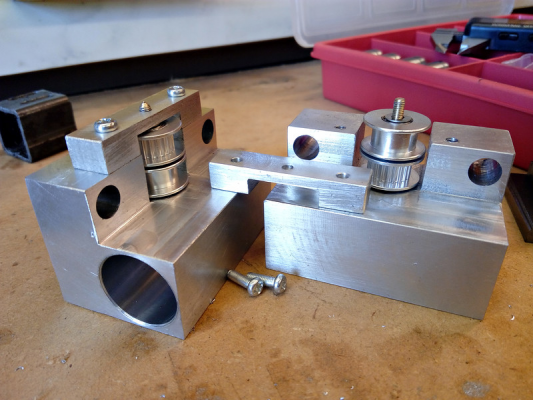
I got the brackets made today, just a couple of 8mm x 10mm x 43mm scraps of ali, with a slot milled in it to accommodate the upper bearing.
Not much, but some forward progress.
Tim
Not much, but some forward progress.
Tim
|
Re: My CoreXY build log May 09, 2017 06:46PM |
Registered: 10 years ago Posts: 770 |
|
Re: My CoreXY build log May 24, 2017 12:43PM |
Registered: 7 years ago Posts: 18 |
That's very true Floyd, it was essential on this build as some of the ball-raced-pulleys are only 3mm bore. That would be a bit bendy when the belts were tensioned.
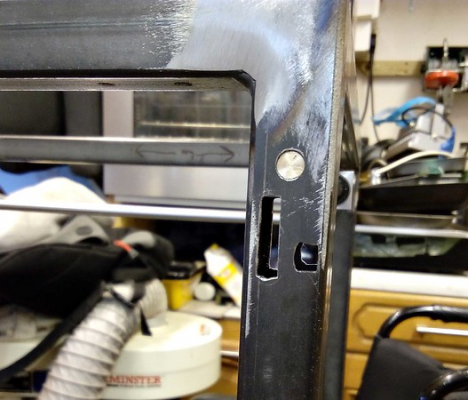
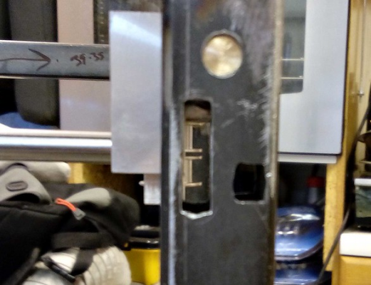
I got a little time in the workshop and started by drilling some oblong holes. (now I know why square drill bits are so expensive, but they would have saved a lot of sweat and effort with drills & files)
This might make it a bit more obvious what they are for
ok, one more
From another angle
The square holes are pretty rough looking, I will tidy them up a bit later when the belt path is more precisely known. I could have got away with making both of the holes the same size (the smaller size), but hey ho, it is what it is.
Next up will be drilling and tapping the carriage blocks for grub screws to grip the 8mm x-axis bars, and shortening the same 8mm bars to their proper length. This will allow me to measure precisely the distance between centres of the pulleys of both carriages, then I can make up a bracket to hold the pulleys at the front of the printer frame (for the rest of the belt path). I will probably also drill and tap a couple of holes to stop the 12mm linear bearings from sliding out.
Then will be the making of the mounting hardware for the X & Y steppers. I've been thinking about the X & Y resolution, using 200 step stepper motors, and even using 16 tooth pulleys on the steppers, that will give me a full-step resolution of 0.16mm (32 mm of belt movement per rev, divided by 200 steps per rev = ) Using 20 tooth pulleys on the steppers will give me 0.2mm full-step resolution.
However, I have had a cunning plan. I have a couple of 36 tooth pulleys, which I could pair with either 20 or 16 tooth pulleys, and make a belt-drive reduction (I also have some short loops of GT2 belt) of either 2.25:1 or 1.8:1. As I have no experience with 3d printers, has anyone any experience with adding belt-reduction "gearing" to increase the resolution?
I know about micro-stepping, and I will definitely be using that (primarily to quieten the steppers), but I do know that the individual micro-steps are not exactly evenly spaced between full steps, hence the thought that micro-stepping would not be the most accurate way of increasing resolution.
On the other hand, adding a belt-driven reduction may also increase "springy-ness" ( actual scientific term there ) and resonance when abrupt direction changes are made. It certainly will reduce the travel speed by the same factor of reduction, but will also increase the torque.
If anyone has any thoughts/opinions, speak now ( or later, I won't be working on this part for a couple of weeks or more )
Until next time....
Tim
|
Re: My CoreXY build log May 26, 2017 01:21PM |
Registered: 7 years ago Posts: 18 |
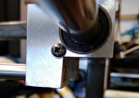
I managed to grab a few mins in the workshop today and drilled and tapped for M6 grub screws to grip the 8mm ground rods. Then I drilled and tapped some M3 holes to hold the 12mm linear bearing in the carriages. (I drilled/tapped 1 hole at each end, carefully positioned so that the M3 washer is just protruding over the edge of the bearing)
View of the M6 holes (I counter-bored 6.2mm to a depth of 20mm, leaving approx' 9mm to tap M6, much easier to tap)
Onwards and sideways
Tim
View of the M6 holes (I counter-bored 6.2mm to a depth of 20mm, leaving approx' 9mm to tap M6, much easier to tap)
Onwards and sideways
Tim
|
Re: My CoreXY build log May 26, 2017 07:27PM |
Registered: 8 years ago Posts: 338 |
|
Re: My CoreXY build log May 27, 2017 01:59AM |
Registered: 7 years ago Posts: 18 |
Quote
Qdeathstar
Looking pretty skookem. What kind of mill do you got? I really want to get one... was debating between a grizzly or a pm.... with power downfeed and dro. I doubt I'll want to go cnc
Thanks.
I have a little sieg x2 that I converted to CNC, although I mostly use it in "manual" mode by using a jog/shuttle wheel to control movement. I'd say definitely go for the DRO's they'll make a huge difference to your accuracy and your speed (as you won't have to keep stopping to measure the part to make sure you haven't gone too far)
As to which mill to recommend, I say go for the largest capacity mill you can afford, but remember that you will most likely spend an equal amount on tooling/accessories.
Tim
|
Re: My CoreXY build log June 01, 2020 03:43PM |
Registered: 7 years ago Posts: 18 |
Well, it's amazing how life can get in the way of building a 3D printer!!!
So after quite a long break from this project, I've been getting back into this again. There's not a huge amount to show from the last few weeks, but I've been getting a few small items ticked off the "to-do" list.
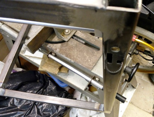
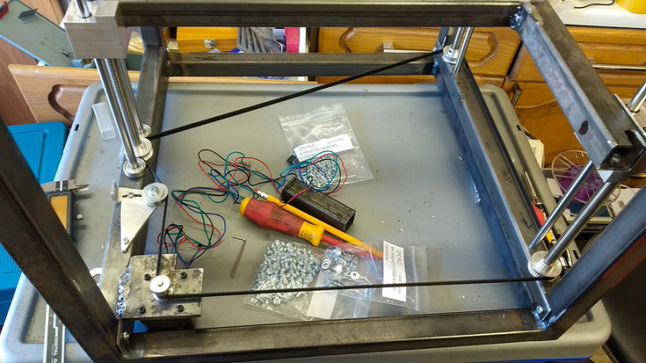
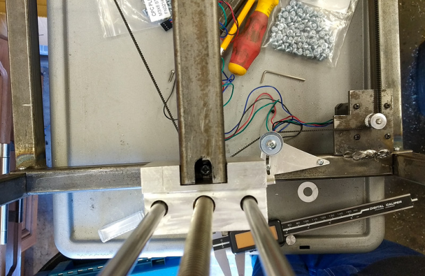
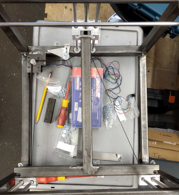
Here's a shot of where I'm up to at the moment, I've been working on the Z-axis which is based on 3 leadscrews coupled with some 8mm smooth rods. This is a poor semi-overhead view
I made a frame consisting of an upper and lower sections of 25mm box steel, well actually I made 2 frames, one for the front and one frame for the back, and these are where the Z-axis guide rods and leadscrews will be held in.
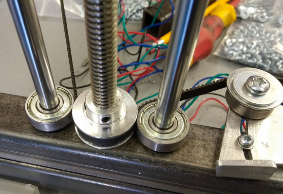
The leadscrews have been turned down to 8mm at their ends where they go into the 25mm box-section steel, and for each leadscrew there are 2 flange-bearings (countersunk one each on the top and bottom sides of the box-section) which keeps them running smoothly, and the 40t pulleys are also 8mm bore.
I very precisely drilled and bored the 25mm box-section frames for each set of holes (for each front carriage there is one guide rod exactly 25mm centres from the leadscrew, for the rear carriage there was 2 guide rods, both exactly 25mm centres from a central leadscrew). There are 2 lengths of 25mm box section in each frame, one set for the rear, and one set for the front. Each set were drilled and bored together to ensure alignment was kept accurate.
The 25mm box-section frames were carefully milled to length to be a precise, snug fit into the main printer frame, and thus they only need a M4 screw at each end to hold them in place. (they actually hold themselves in place without the screws, but the screws make sure that when everything is moving and warmed up, nothing will move)
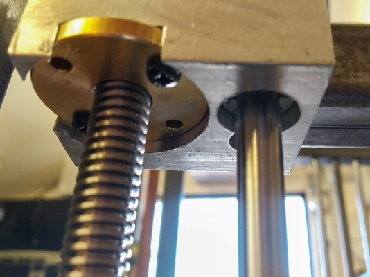
The Z-axis carriages are milled out of aluminium bar, here's a shot of one of the front 2 carriages taken from below (the other 2 holes are drilled and tapped for mounting the leadscrew-nut, but as it's in-progress it's not worth putting them in as they'll be dis-assembled and re-assembled a good few times before the whole thing is done)
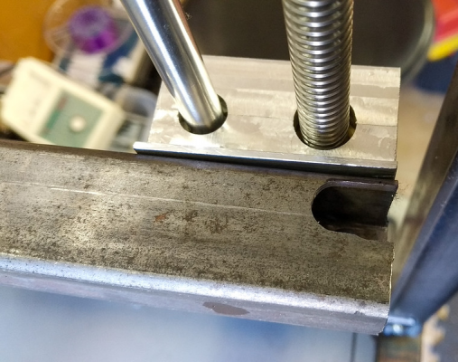
and from above, also showing the "T" piece of 25mm box steel that the bed will mount onto;
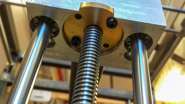
And the rear central Z carriage with 2 guide-rods (2 are not strictly needed, but they turned out to be useful for holding bearings for guiding the belt) from below, showing the 2 Igus bearings (held in a blind pocket) and the leadscrew nut.
and from above,;
You can see on that pic the "T" piece that links all 3 Z-axis carriages, and also you can see the present fixing arrangement (a M4 screw attaching it to the carriages thru a slot in the "T" piece). This is going to be changed as I have an idea to incorporate the bed levelling into this mounting.
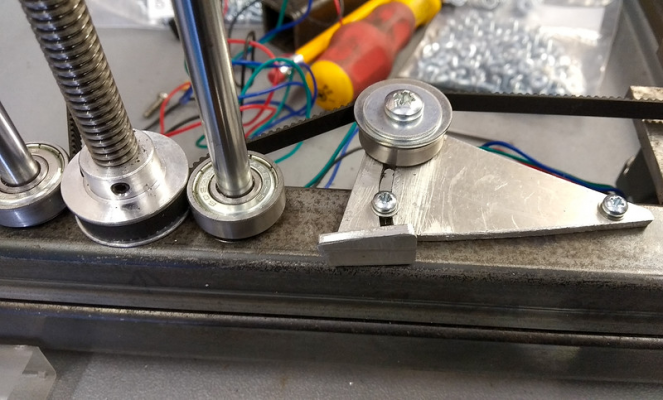
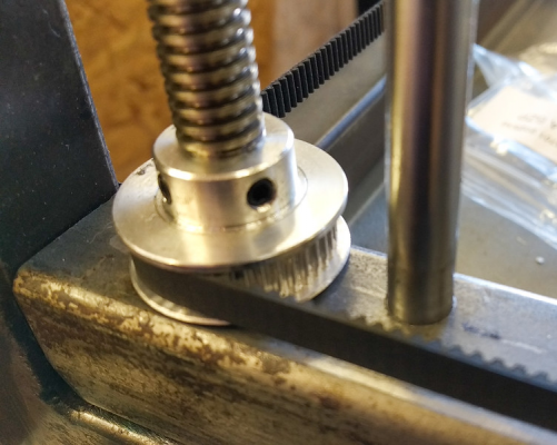
This is a shot of the routing of the Z-axis belt around the rear central carriage leadscrew and guide-rods. I wanted to make sure that the belt had >90 degrees of contact on each of the pulleys driving the leadscrews, so you can see that the 2 guide-rods were very handy to pop a couple of bearings on to help "wrap" and guide the belt around the 40t pulley
A wider view showing the belt-tensioning device
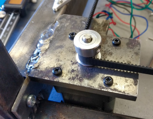
And a close-up view of the Z stepper mount;
Here's a closer shot of how the belt routes around one of the front leadscrews and guide-rod;
The leadscrews are 2mm pitch, and they are driven by 40t pulleys, the Z stepper has a 20t pulley on it, which (by my rough calculations) will give a full-step resolution of 0.005mm (more than I need, I may put a 40t pulley on the stepper to ease the radius of the belt round the stepper)
One of the 3 leadscrews has virtually no runout/wobble, but the other 2 need some "adjustment" to get them closer to running true. It doesn't seem to wobble the whole carriage, but there is a slight, but noticeable, increase of resistance to the belt movement. So the plan is to take them out and then find out exactly where the bend is and attempt to straighten it out.
So next up is straightening out the 2 wobbly leadscrews, and then sorting out the bed-levelling arrangements and the mountings for the bed itself.
Stay tuned for the next update (but maybe don't hold your breath, LOL!!)
|
Re: My CoreXY build log June 01, 2020 04:11PM |
Registered: 11 years ago Posts: 250 |
|
Re: My CoreXY build log June 02, 2020 05:37AM |
Registered: 6 years ago Posts: 1,007 |
To insure the guides are in a plane, instead of long bars, you can use a laser, either a spirit level with one included, easy to make if none available. Rest it on the two guides, aim a point 10 or more meters away on a wall for ex, mark it then move the level along the guides, adjust one guide till you can hit the same point. Once they are in the same plane, make them // with a gauge that can be a rod cut to the correct length with eventually an adjusting screw or a set of shims whatever.
"A comical prototype doesn't mean a dumb idea is possible" (Thunderf00t)
"A comical prototype doesn't mean a dumb idea is possible" (Thunderf00t)
|
Re: My CoreXY build log June 17, 2020 12:11PM |
Registered: 7 years ago Posts: 18 |
Thanks for that hint MKSA, I'll try to remember that one.
So a little more progress to report.
I took each of the leadscrew's off and straightened them so that they are running true with less than 0.5mm "wobble" at the end of one screw, and less than 0.2mm with the other 2 screws. (I could've spent much longer on it to get even less runout, but it seemed to be diminishing returns, and I was happy to get well below 1mm runout. Now when I run the Z-axis carriage's all the way up and down there is no sign of the binding that was before.
I also added a piece of small steel angle to join the front 2 Z-axis carriages (actually to prevent a very slight twisting of them when the leadscrew was turned).
I then turned to the "T" frame that the bed will attach to. This is the 2nd frame that I've welded up, the 1st I trimmed too much, and then on this 2nd one I milled out some slots for mounting, and then changed my mind on the mounting plans. Not wishing to waste it, I ended up welding up the "not-needed" slots.
Here is an overhead view of the bed-frame;
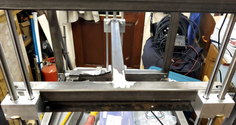
and the view from the front;
The idea is that it is this bed-frame that will be levelled, and the bed itself will be fixed (although with allowance for thermal expansion in the X and Y directions) to the bed-frame
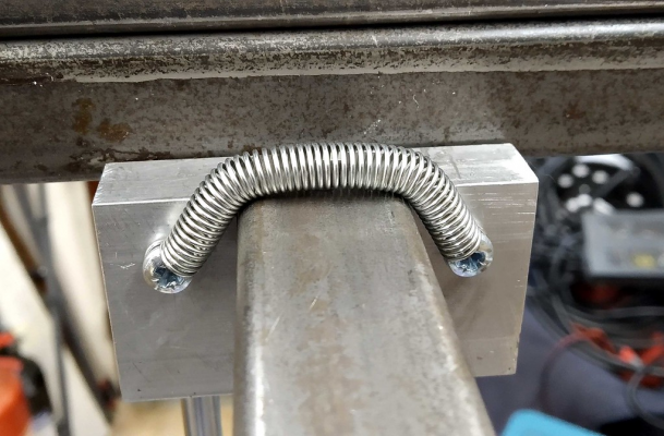
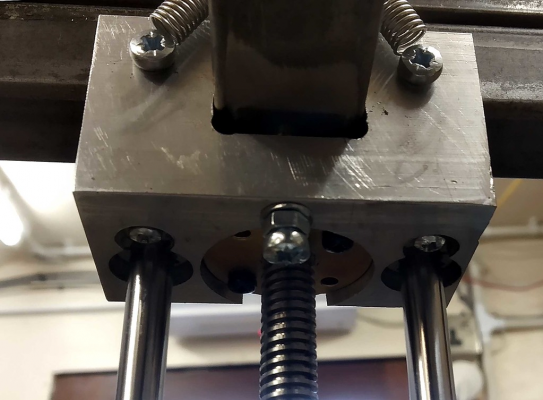
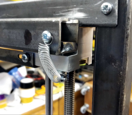
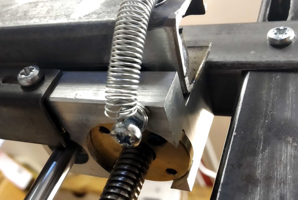
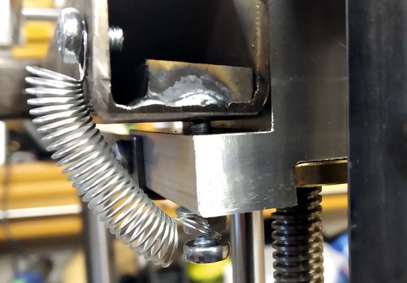
A closer view of how the bed-frame is held to the back Z-axis carriage, the frame just sits nicely in the milled socket and is held down by a spring;
and the view from under it, showing the levelling screw (and it's locking nut)
The bed-frame is similarly held by springs onto the front Z-axis carriages;
view from underneath;
Close up view of the levelling screw;
Next up will be the mounts for attaching the bed to the bed-frame.
Thanks for watching,
Tim
|
Re: My CoreXY build log June 21, 2020 04:14PM |
Registered: 11 years ago Posts: 1,049 |
Please get some socket head bolts and a set of hex drivers
Phillips head screws for wood working (maybe)
Bed
See Digital Dentist:
UMMD 3D Printer Bed Design
[drmrehorst.blogspot.com]
You may need Kinematic Leveling with steel / aluminum interfaces
aluminum lead screw block to steel bed to aluminum bed plate
thermal differences

Phillips head screws for wood working (maybe)
Bed
See Digital Dentist:
UMMD 3D Printer Bed Design
[drmrehorst.blogspot.com]
You may need Kinematic Leveling with steel / aluminum interfaces
aluminum lead screw block to steel bed to aluminum bed plate
thermal differences

|
Re: My CoreXY build log June 21, 2020 04:55PM |
Registered: 11 years ago Posts: 5,780 |
Updates to be support design here: [drmrehorst.blogspot.com]
Ultra MegaMax Dominator 3D printer: [drmrehorst.blogspot.com]
Ultra MegaMax Dominator 3D printer: [drmrehorst.blogspot.com]
|
Re: My CoreXY build log June 22, 2020 08:38AM |
Registered: 7 years ago Posts: 18 |
Thanks for taking the time to look and comment,
I may well replace the screws with socket head bolts, but for this stage these seem to be doing the job quite adequately, and I have plenty of these already in stock.
Is there an advantage of socket head bolts over pozidrive? It's not like these have to be torqued up 'til they squeek
I have been following your blog and am very impressed with your approach to the physics and accuracy of the physical parts. I very much believe in trying to get things engineered as accurately as I can, rather than relying on software tricks to make up for inaccuracies/errors in construction. So I have been borrowing and adapting a number of the things you've done. That Includes the Kinematic-type mounting for the bed itself (but as you have seen, I've incorporated the actual levelling into the Z-axis carriage > bed-frame mounts), I'm hoping to implement a slightly different method due to not having a big enough piece of Aluminium for the heat-bed to include similar mounting "ears" that feature in the Digital Dentist's setup.
Regarding the interface of the aluminium leadscrew blocks/carriages to the steel bed-frame, although different materials, there shouldn't be a big temperature difference between them as the underside of the bed heater itself will hopefully be insulated (so radiant heat shouldn't raise the bed-frame temp too much). Even if the bed does heat the steel frame up more than I anticipate, steel does not expand as much as Ali, and it also conducts heat less well than Ali'. In addition, the steel bed-frame is not fixed rigidly to the Ali' leadscrew carriages, but is held in place by the springs and the shape of the carriages and the weight of the whole bed assembly, but there's also enough room for either/both frame and/or carriages to expand due to heat.
I have no plans at the moment to heat the print chamber (apart from the heat from the bed), but I do intend to enclose the print chamber.
According to my calculations, the 300mm x 300mm Aluminium bed will expand by 0.6mm when heated from 15 to 100 degrees C, but I hope to allow for approx' 1.5-2mm expansion in mounting the bed to the bed-frame.
The Bed itself is going to be raised above the bed-frame by about 15mm to allow space for the (230v) bed heater & thermal cutout, and some insulation.
Tim
Quote
cozmicray
Please get some socket head bolts and a set of hex drivers
Phillips head screws for wood working (maybe)
I may well replace the screws with socket head bolts, but for this stage these seem to be doing the job quite adequately, and I have plenty of these already in stock.
Is there an advantage of socket head bolts over pozidrive? It's not like these have to be torqued up 'til they squeek
Quote
Bed
See Digital Dentist:
UMMD 3D Printer Bed Design
[drmrehorst.blogspot.com]
You may need Kinematic Leveling with steel / aluminum interfaces
aluminum lead screw block to steel bed to aluminum bed plate
thermal differences
Quote
Updates to be support design here: [drmrehorst.blogspot.com]
I have been following your blog and am very impressed with your approach to the physics and accuracy of the physical parts. I very much believe in trying to get things engineered as accurately as I can, rather than relying on software tricks to make up for inaccuracies/errors in construction. So I have been borrowing and adapting a number of the things you've done. That Includes the Kinematic-type mounting for the bed itself (but as you have seen, I've incorporated the actual levelling into the Z-axis carriage > bed-frame mounts), I'm hoping to implement a slightly different method due to not having a big enough piece of Aluminium for the heat-bed to include similar mounting "ears" that feature in the Digital Dentist's setup.
Regarding the interface of the aluminium leadscrew blocks/carriages to the steel bed-frame, although different materials, there shouldn't be a big temperature difference between them as the underside of the bed heater itself will hopefully be insulated (so radiant heat shouldn't raise the bed-frame temp too much). Even if the bed does heat the steel frame up more than I anticipate, steel does not expand as much as Ali, and it also conducts heat less well than Ali'. In addition, the steel bed-frame is not fixed rigidly to the Ali' leadscrew carriages, but is held in place by the springs and the shape of the carriages and the weight of the whole bed assembly, but there's also enough room for either/both frame and/or carriages to expand due to heat.
I have no plans at the moment to heat the print chamber (apart from the heat from the bed), but I do intend to enclose the print chamber.
According to my calculations, the 300mm x 300mm Aluminium bed will expand by 0.6mm when heated from 15 to 100 degrees C, but I hope to allow for approx' 1.5-2mm expansion in mounting the bed to the bed-frame.
The Bed itself is going to be raised above the bed-frame by about 15mm to allow space for the (230v) bed heater & thermal cutout, and some insulation.
Tim
Sorry, only registered users may post in this forum.
